Table of Contents
Advertisement
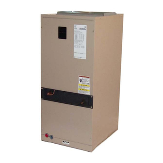
INSTALLATION MANUAL
SINGLE PIECE
AIR HANDLERS
MODELS: F*FP
SAFETY . . . . . . . . . . . . . . . . . . . . . . . . . . . . . . . . . . . . . . . . . . . . . . . .1
SPECIFIC SAFETY RULES AND PRECAUTIONS . . . . . . . . . . . . . . .2
SAFETY REQUIREMENTS . . . . . . . . . . . . . . . . . . . . . . . . . . . . . . . . .2
GENERAL INFORMATION . . . . . . . . . . . . . . . . . . . . . . . . . . . . . . . . .2
INSPECTION . . . . . . . . . . . . . . . . . . . . . . . . . . . . . . . . . . . . . . . . . . . .2
LIMITATIONS . . . . . . . . . . . . . . . . . . . . . . . . . . . . . . . . . . . . . . . . . . . .2
CLEARANCES . . . . . . . . . . . . . . . . . . . . . . . . . . . . . . . . . . . . . . . . . . .2
LOCATION . . . . . . . . . . . . . . . . . . . . . . . . . . . . . . . . . . . . . . . . . . . . . .2
HORIZONTAL DRAIN PAN CONVERSION . . . . . . . . . . . . . . . . . . . .3
DUCT CONNECTIONS . . . . . . . . . . . . . . . . . . . . . . . . . . . . . . . . . . . .5
AIR FILTERS . . . . . . . . . . . . . . . . . . . . . . . . . . . . . . . . . . . . . . . . . . . .5
SUSPENSION KITS . . . . . . . . . . . . . . . . . . . . . . . . . . . . . . . . . . . . . . .5
Plenum Clearances . . . . . . . . . . . . . . . . . . . . . . . . . . . . . . . . . . . . . . .3
Typical Installation . . . . . . . . . . . . . . . . . . . . . . . . . . . . . . . . . . . . . . . .3
Filter Access & Drain Pan Conversion / Coil Baffle . . . . . . . . . . . . . . .4
Dimensions & Duct Sizes . . . . . . . . . . . . . . . . . . . . . . . . . . . . . . . . . . .4
Typical Horizontal Installation . . . . . . . . . . . . . . . . . . . . . . . . . . . . . . .5
TXV Bulb Installation . . . . . . . . . . . . . . . . . . . . . . . . . . . . . . . . . . . . . .5
Bulb Location . . . . . . . . . . . . . . . . . . . . . . . . . . . . . . . . . . . . . . . . . . . .6
Dimensions . . . . . . . . . . . . . . . . . . . . . . . . . . . . . . . . . . . . . . . . . . . . .4
Installed TXV Sizes . . . . . . . . . . . . . . . . . . . . . . . . . . . . . . . . . . . . . . .5
Physical and Electrical Data . . . . . . . . . . . . . . . . . . . . . . . . . . . . . . . . .8
Electrical Data - Cooling Only (50 & 60 Hz) . . . . . . . . . . . . . . . . . . . . .8
Conversion Table . . . . . . . . . . . . . . . . . . . . . . . . . . . . . . . . . . . . . . . . .8
Electrical Data - 1 Ø - 208/230-1-60 . . . . . . . . . . . . . . . . . . . . . . . . . .9
Copper Wire 1 Ø - 208/230-1-60 . . . . . . . . . . . . . . . . . . . . . . . . . . . .10
SAFETY
This is a safety alert symbol. When you see this symbol on
labels or in manuals, be alert to the potential for personal
injury.
Understand and pay particular attention to the signal words DANGER,
WARNING, or CAUTION.
DANGER indicates an imminently hazardous situation, which, if not
avoided, will result in death or serious injury.
WARNING indicates a potentially hazardous situation, which, if not
avoided, could result in death or serious injury.
CAUTION indicates a potentially hazardous situation, which, if not
avoided may result in minor or moderate injury. It is also used to
alert against unsafe practices and hazards involving only property dam-
age.
TABLE OF CONTENTS
COIL METERING DEVICES . . . . . . . . . . . . . . . . . . . . . . . . . . . . . . . . 5
REFRIGERANT LINE CONNECTION . . . . . . . . . . . . . . . . . . . . . . . . 6
ELECTRIC HEATERS AND OPERATING CONTROLS . . . . . . . . . . 6
LOW VOLTAGE CONTROL CONNECTION . . . . . . . . . . . . . . . . . . . 7
LINE POWER CONNECTIONS . . . . . . . . . . . . . . . . . . . . . . . . . . . . . 7
BLOWER SPEED CONNECTIONS . . . . . . . . . . . . . . . . . . . . . . . . . . 7
DRAIN CONNECTIONS . . . . . . . . . . . . . . . . . . . . . . . . . . . . . . . . . . 15
MAINTENANCE . . . . . . . . . . . . . . . . . . . . . . . . . . . . . . . . . . . . . . . . 15
COIL CLEANING . . . . . . . . . . . . . . . . . . . . . . . . . . . . . . . . . . . . . . . 15
LUBRICATION . . . . . . . . . . . . . . . . . . . . . . . . . . . . . . . . . . . . . . . . . 15
CONDENSATE DRAINS . . . . . . . . . . . . . . . . . . . . . . . . . . . . . . . . . 15
LIST OF FIGURES
Control Board . . . . . . . . . . . . . . . . . . . . . . . . . . . . . . . . . . . . . . . . . . . 6
Line Power Connections . . . . . . . . . . . . . . . . . . . . . . . . . . . . . . . . . . . 7
Blower Speed Connections . . . . . . . . . . . . . . . . . . . . . . . . . . . . . . . . 7
Cooling Models with Electric Heat Wiring . . . . . . . . . . . . . . . . . . . . . 14
Single Stage Heat Pump Control Wiring . . . . . . . . . . . . . . . . . . . . . . 14
LIST OF TABLES
Copper Wire 1 Ø - 208/230-1-601 . . . . . . . . . . . . . . . . . . . . . . . . . . 10
Electrical Data - 3 Ø - 208/230-3-60 . . . . . . . . . . . . . . . . . . . . . . . . . 11
Copper Wire 3 Ø - 208/230-3-60 . . . . . . . . . . . . . . . . . . . . . . . . . . . 11
Airflow Data for 230 Volt - Heat Pump Models . . . . . . . . . . . . . . . . . 12
Airflow Data for 208 Volt - Heat Pump Models . . . . . . . . . . . . . . . . . 13
Troubleshooting Guide . . . . . . . . . . . . . . . . . . . . . . . . . . . . . . . . . . . 15
Improper installation may create a condition where the operation of
the product could cause personal injury or property damage.
Improper installation, adjustment, alteration, service or mainte-
nance can cause injury or property damage. Refer to this manual
for assistance or for additional information, consult a qualified con-
tractor, installer or service agency.
This product must be installed in strict compliance with the installa-
tion instructions and any applicable local, state, and national codes
including, but not limited to building, electrical, and mechanical
codes.
ISO 9001
Certified Quality
Management System
404912-UIM-A-0508
Advertisement
Table of Contents

Subscribe to Our Youtube Channel
Related Manuals for York F4FP024H06T3X


Summary of Contents for York F4FP024H06T3X
-
Page 1: Table Of Contents
INSTALLATION MANUAL SINGLE PIECE AIR HANDLERS MODELS: F*FP ISO 9001 Certified Quality Management System TABLE OF CONTENTS SAFETY ..........1 COIL METERING DEVICES . -
Page 2: Specific Safety Rules And Precautions
404912-UIM-A-0508 SPECIFIC SAFETY RULES AND PRECAUTIONS The unit can be positioned for bottom return air in the upflow position, and right or left return in the horizontal position. Top and side power wiring and control wiring, accessible screw termi- nals for control wiring, easy to install drain connections and electric heaters all combine to make the installation easy, and minimize installa- FIRE OR ELECTRICAL HAZARD tion cost. -
Page 3: Horizontal Drain Pan Conversion
404912-UIM-A-0508 The coil is provided with a secondary drain. It should be piped to a loca- MINIMUM CLEARANCE tion that will give the occupant a visual warning that the primary drain is OF 1” ALL SIDES clogged. If the secondary drain is not used it must be capped. When an evaporator coil is installed in an attic or above a finished ceiling, an auxiliary drain pan should be provided under the coil as is specified by most local building codes. -
Page 4: Filter Access & Drain Pan Conversion / Coil Baffle
404912-UIM-A-0508 BLOWER 3A - FRONT VIEW COMPARTMENT (ACCESS PANEL PRIMARY REMOVED) SUPPORT DRAIN BRACKET BLOWER PRIMARY HOUSING 3/4" PVC SOCKETS DRAIN FOR HORIZONTAL 060 COIL BAFFLE DRAIN APPLICATION SECONDARY (SHOWN IN DRAIN SECONDARY RIGHT-HORIZONTAL DRAIN POSITION) HORIZONTAL CENTER ACCESS PANEL DRAIN PAN 3C - FRONT VIEW POSITION "B”... -
Page 5: Duct Connections
F4FP024H06T2B TXV 2B the heating season or through an uncooled space during the cooling F4FP024H06T3X None season. The use of a vapor barrier is recommended to prevent absorp- F4FP030H06T2A TXV 2A tion of moisture from the surrounding air into the insulation. -
Page 6: Bulb Location
404912-UIM-A-0508 The TXV is bolted into the coil assembly of this Air Handler unit at the Braze the suction line. Re-attach the center access panel, if it had factory. The temperature sensing bulb will need to be attached to the been removed. -
Page 7: Low Voltage Control Connection
404912-UIM-A-0508 Field supplied low voltage wiring can exit the unit on the top right hand HEAT KIT ASSEMBLY REMOVE 3 SCREWS TO corner or the right hand side panel (see Fig. 5, item K). REMOVE THE CIRCUIT BREAKER BRACKET Install a 7/8" plastic bushing in the selected hole and keep low voltage FROM HEAT KIT ASSEMBLY wiring as short as possible inside the control box. -
Page 8: Physical And Electrical Data
404912-UIM-A-0508 TABLE 3: Physical and Electrical Data Models F*FP Blower - Diameter x Width 10 x 6 10 x 8 10 x 8 10 x 8 Motor Nominal RPM 1075 1075 1075 1075 Voltage 208/230 Full Load (208/230) 1.6/1.4 (50 Hz:2.1) 2.5 / 2.2 3.3/2.9 (50 Hz:2.3) 2.5 / 2.2... -
Page 9: Electrical Data - 1 Ø - 208/230-1-60
404912-UIM-A-0508 TABLE 6: Electrical Data - 1 Ø - 208/230-1-60 Max. Static Total Heat KW Staging Heater* & Min. CFM Models F*FP W1 Only W2 Only W1 + W2 Model Static 208V 240V 208V 240V 208V 240V 208V 240V 208V 240V 2HK*6500506B 13.0... -
Page 10: Electrical Data - (For Single Source Power Supply) - Copper Wire 1 Ø - 208/230-1-60
404912-UIM-A-0508 TABLE 7: Electrical Data - (For Single Source Power Supply) - Copper Wire 1 Ø - 208/230-1-60 Field Wiring Heater Heater* Models F*FP Amps Min. Circuit Ampacity 75°C Wire Size - AWG Max. O.C.P. Amps/Type Model 240V 208V 240V 208V 240V 208V... -
Page 11: Electrical Data - 3 Ø - 208/230-3-60
404912-UIM-A-0508 TABLE 9: Electrical Data - 3 Ø - 208/230-3-60 Total Heat KW Staging Max. Static Heater & Min. CFM Models F*FP W1 Only W2 Only W1 + W2 Model Static 2HK06501025B 10.0 25.6 34.1 10.0 2HK06501025B 10.0 25.6 34.1 10.0 2HK06501525B High... -
Page 12: Airflow Data For 230 Volt - Heat Pump Models
404912-UIM-A-0508 TABLE 11: Airflow Data for 230 Volt - Heat Pump Models 230 Volt Blower Motor Models CFM @ External Static Pressure - IWC Speed 0.10 0.20 0.30 0.40 0.50 0.60 0.70 0.80 0.90 1.00 High F4FP024H06T** High 1,270 1,210 1,150 1,085 1,015... -
Page 13: Airflow Data For 208 Volt - Heat Pump Models
404912-UIM-A-0508 TABLE 12: Airflow Data for 208 Volt - Heat Pump Models 208 Volt Blower Motor Models CFM @ External Static Pressure - IWC Speed 0.10 0.20 0.30 0.40 0.50 0.60 0.70 0.80 0.90 1.00 High F4FP024H06T** Med. High 1143 1089 1035 F4FP030H06T**... -
Page 14: Cooling Models With Electric Heat Wiring
404912-UIM-A-0508 F* SERIES F* SERIES Air Handler Control Wiring Air Handler Control Wiring Typical A/C - Cooling only Applications Typical A/C with Electric Heat Applications AIR HANDLER AIR HANDLER THERMOSTAT THERMOSTAT 1 - STAGE 1 - STAGE BOARD BOARD AIR CONDITIONING AIR CONDITIONING Field HUMIDISTAT... -
Page 15: Drain Connections
404912-UIM-A-0508 DRAIN CONNECTIONS The drain pan connections are designed to ASTM Standard D 2466 Schedule 40. 3/4" PVC is preferred. Since the drains are not subject to All drain lines should be trapped a minimum of three inches, should be any pressure it is not necessary to use Schedule 40 pipe for drain lines. -
Page 16: Uim-A
NOTES Subject to change without notice. Printed in U.S.A. 404912-UIM-A-0508 Copyright © 2008 by Johnson Controls, Inc. All rights reserved. Supersedes: 292043-UIM-B-0707 Johnson Controls Unitary Products 5005 York Drive Norman, OK 73069...
Need help?
Do you have a question about the F4FP024H06T3X and is the answer not in the manual?
Questions and answers