Table of Contents
Advertisement
Quick Links
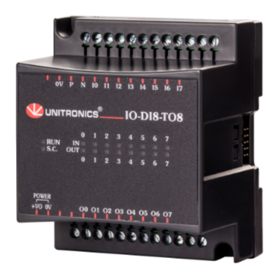
IO-DI8-TO8, IO-DI8-TO8-L
The IO-DI8-TO8 and IO-DI8-TO8-L are I/O
expansion modules that can be used in
conjunction with specific Unitronics OPLC
controllers.
The modules are identical except for their
voltage specifications: IO-DI8-TO8 runs at
24 VDC; IO- DI8-TO8-L at 12 VDC.
Both modules offer 8 digital inputs, type
pnp/npn (source/sink), and 8 pnp (source)
transistor outputs.
The interface between a module and the
OPLC is provided by an adapter.
These modules may either be snap-
mounted on a DIN rail, or screw-mounted
onto a mounting plate.
Component identification
1
Module-to-module connector
2
Status indicators
3
Connection points for power
supply to outputs
4
Output connection points
5
Module-to-module connector port
6
Input connection points
Before using this product, it is the responsibility of the user to read and understand this document and any
accompanying documentation.
All examples and diagrams shown herein are intended to aid understanding, and do not guarantee
operation. Unitronics accepts no responsibility for actual use of this product based on these examples.
Please dispose of this product in accordance with local and national standards and regulations.
Only qualified service personnel should open this device or carry out repairs.
User safety and equipment protection guidelines
This document is intended to aid trained and competent personnel in the installation of this equipment as
defined by the European directives for machinery, low voltage, and EMC. Only a technician or engineer trained
in the local and national electrical standards should perform tasks associated with the device's electrical wiring.
Symbols are used to highlight
information relating to the user's
personal safety and equipment
protection throughout this document.
When these symbols appear, the
associated information must be read
carefully and understood fully.
Failure to comply with appropriate safety guidelines can result in severe personal injury or
property damage. Always exercise proper caution when working with electrical equipment.
Unitronics Industrial Automation
I/O Expansion Modules 8 Inputs, 8 Outputs
1
2
3
Symbol
Meaning
Description
The identified danger causes physical
Danger
and property damage.
The identified danger can cause
Warning
physical and property damage.
Caution
Caution
Use caution.
6
5
4
1
Advertisement
Table of Contents

Related Manuals for Unitronics IO-DI8-TO8


Summary of Contents for Unitronics IO-DI8-TO8
- Page 1 All examples and diagrams shown herein are intended to aid understanding, and do not guarantee operation. Unitronics accepts no responsibility for actual use of this product based on these examples. Please dispose of this product in accordance with local and national standards and regulations.
-
Page 2: Environmental Considerations
Snap the device onto the DIN rail as shown below; the module will be squarely situated on the DIN rail. 80mm (3.15") Screw-Mounting The figure on the next page is drawn to scale. It may be used as a guide for screw-mounting the module. Mounting screw type: either M3 or NC6-32. Unitronics Industrial Automation... - Page 3 I O - D I 8 - T O 8 , I O - D I 8 - T O 8 - L I / O E x p a n s i o n M o d u l e s 80mm (3.15") 5.8mm 68.4mm (0.228") (2.693") (0.16") 4mm (x2) (0.16") Unitronics Industrial Automation...
-
Page 4: Connecting Expansion Modules
Allow for voltage drop and noise interference with input/output lines used over an extended distance. Use wire that is properly sized for the load. The adapter and I/O signals must be connected to the same 0V signal. Unitronics Industrial Automation... - Page 5 Do not connect the ‘Neutral or ‘Line’ signal of the 110/220VAC to the device’s 0V pin. Circuit Protection Device In the event of voltage fluctuations or non-conformity to voltage power supply Outputs' specifications, connect the device to a power supply regulated power supply. Unitronics Industrial Automation...
- Page 6 (source) or npn (sink) Galvanic isolation None Status indicators Green LEDs—Lit when the corresponding input is active. See Note 1. (IN) 24VDC for IO-DI8-TO8, 12VDC for IO-DI8-TO8-L Nominal input voltage Input voltage IO-DI8-TO8 IO-DI8-TO8-L pnp (source) 0-5VDC for Logic ‘0’...
- Page 7 7. Its I/Os are addressed accordingly. Example Input #5, located on an EX90-DI8-RO8 connected to an OPLC will be addressed as I 149, 149 = 32 + 7 • 16 + 5 Unitronics Industrial Automation...
- Page 8 Unitronics products referred to herein in any manner deviating from the recommendations made in this document. Unitronics assumes no responsibility for the use of any parts, components, or other ancillary appliances including circuitry other than as recommended hereunder or other than that embodied in the Unitronics product.
Need help?
Do you have a question about the IO-DI8-TO8 and is the answer not in the manual?
Questions and answers