Table of Contents
Advertisement
Quick Links
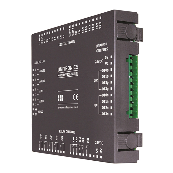
V200-18-E2B
The V200-18-E2B
plugs directly into the
back of compatible
Unitronics OPLCs,
creating a self-
contained PLC unit
with a local I/O
configuration.
Before using this product, it is the responsibility of the user to read and understand this document and any
accompanying documentation.
All examples and diagrams shown herein are intended to aid understanding, and do not guarantee
operation. Unitronics accepts no responsibility for actual use of this product based on these examples.
Please dispose of this product in accordance with local and national standards and regulations.
Only qualified service personnel should open this device or carry out repairs.
User safety and equipment protection guidelines
This document is intended to aid trained and competent personnel in the installation of this equipment as
defined by the European directives for machinery, low voltage, and EMC. Only a technician or engineer trained
in the local and national electrical standards should perform tasks associated with the device's electrical wiring.
Symbols are used to highlight
information relating to the user's
personal safety and equipment
protection throughout this document.
When these symbols appear, the
associated information must be read
carefully and understood fully.
Failure to comply with appropriate safety guidelines can result in severe personal injury or
property damage. Always exercise proper caution when working with electrical equipment.
Check the user program before running it.
Do not attempt to use this device with parameters that exceed permissible levels.
Install an external circuit breaker and take appropriate safety measures against short-circuiting
in external wiring.
To avoid damaging the system, do not connect / disconnect the device when the power is on.
Caution
Ascertain that terminal blocks are properly secured in place.
Environmental Considerations
Do not install in areas with: excessive or conductive dust, corrosive or flammable gas,
moisture or rain, excessive heat, regular impact shocks or excessive vibration.
Provide proper ventilation by leaving at least 10mm of space between the top and bottom
edges of the device and the enclosure walls.
Do not place in water or let water leak onto the unit.
Do not allow debris to fall inside the unit during installation.
Unitronics
Snap-in I/O Module
Features
16 isolated digital inputs, including 2 high-speed counter inputs,
type pnp/npn (source/sink)
10 isolated relay outputs
4 isolated pnp/npn (source/sink) transistor outputs,
including 2 high-speed outputs
2 analog inputs
2 analog outputs
Symbol
Meaning
Danger
Warning
Caution
Caution
Description
The identified danger causes physical
and property damage.
The identified danger can cause
physical and property damage.
Use caution.
1
Advertisement
Table of Contents

Subscribe to Our Youtube Channel
Related Manuals for Unitronics V200-18-E2B


Summary of Contents for Unitronics V200-18-E2B
- Page 1 All examples and diagrams shown herein are intended to aid understanding, and do not guarantee operation. Unitronics accepts no responsibility for actual use of this product based on these examples. Please dispose of this product in accordance with local and national standards and regulations.
- Page 2 Press the buttons on the sides of the module and hold them down to open the locking mechanism. Gently rock the module from side to side, easing the module from the controller. Replace the protective cap on the connector. Unitronics...
-
Page 3: Wiring Procedures
Inputs I0 and I2 can be used as normal digital inputs, as high-speed counters, or as part of a shaft encoder. Inputs I1 and I3 can be used as normal digital inputs, as high-speed counter resets, or as part of a shaft encoder. The common signals of each group are internally shorted on each connector. Unitronics... - Page 4 (sink) digital input wiring pnp (source) digital input wiring npn (sink) high-speed counter pnp (source) high-speed counter Inputs I0, I1, and I2, I3 can be used as shaft encoders as shown below. npn (sink) shaft encoder wiring pnp (source) shaft encoder wiring Unitronics...
-
Page 5: Relay Outputs
To increase the life span of the relay output contacts and protect the device from potential damage by reverse EMF, connect: a clamping diode in parallel with each inductive DC load, an RC snubber circuit in parallel with each inductive load. Unitronics... -
Page 6: Transistor Outputs
Shields should be connected at the signal source. Inputs may be wired to work with either current or voltage. Note that the analog input’s 0V signal must be the same 0V used by the controller’s power supply. current current/voltage Unitronics... -
Page 7: Output Wiring
The 24VDC power supply must be turned on and off simultaneously with the controller’s power supply. Output Wiring Shields should be earthed, connected to the earth of the cabinet. An output can be wired to either current or voltage. Do not use current and voltage from the same source channel. current/voltage Unitronics... - Page 8 V 2 0 0 - 1 8 - E 2 B 1 0 / 0 6 S n a p - i n I / O M o d u l e V200-18-E2B Technical Specifications Digital Inputs Number of inputs...
- Page 9 10-bit (1024 units) Resolution at 4-20mA 204 to 1023 (820 units) Conversion time Synchronized to scan time Input impedance >100KΩ—voltage 500Ω—current Galvanic isolation None Absolute maximum rating ±15V—voltage ±30mA—current Full-scale error ±2 LSB (0.2%) Linearity error ±2 LSB (0.2%) Unitronics...
- Page 10 The information in this document reflects products at the date of printing. Unitronics reserves the right, subject to all applicable laws, at any time, at its sole discretion, and without notice, to discontinue or change the features, designs, materials and other specifications of its products, and to either permanently or temporarily withdraw any of the forgoing from the market.
Need help?
Do you have a question about the V200-18-E2B and is the answer not in the manual?
Questions and answers