Advertisement
Quick Links
Snap-in I/O Modules
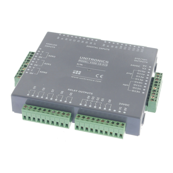
The V200-18-E1B
plugs directly into the back of
compatible Unitronics OPLCs,
creating a self-contained PLC unit
with a local I/O configuration.
General Description
The Snap-in I/O plugs directly into the back of compatible Unitronics PLCs, creating a self-contained PLC unit with a local I/O configuration.
Detailed Installation Guides containing the I/O wiring diagrams for these models, technical specifications, and additional documentation are located
in the Technical Library in the Unitronics website:
Alert Symbols and General Restrictions
When any of the following symbols appear, read the associated information carefully.
Symbol
Meaning
Danger
Warning
Caution
Caution
▪ Before using this product, the user must read and understand this document.
▪ All examples and diagrams are intended to aid understanding, and do not guarantee operation. Unitronics accepts no responsibility for actual use
of this product based on these examples.
▪ Please dispose of this product according to local and national standards and regulations.
▪ Only qualified service personnel should open this device or carry out repairs.
▪ Failure to comply with appropriate safety guidelines can cause severe injury or property damage.
▪ Do not attempt to use this device with parameters that exceed permissible levels.
▪ To avoid damaging the system, do not connect/disconnect the device when power is on.
Environmental Considerations
▪ Do not install in areas with: excessive or conductive dust, corrosive or flammable gas,
moisture or rain, excessive heat, regular impact shocks or excessive vibration, in
accordance with the standards given in the product's technical specification sheet.
▪ Do not place in water or let water leak onto the unit.
▪ Do not allow debris to fall inside the unit during installation.
▪ Ventilation: 10mm space required between controller's top/bottom edges & enclosure walls.
▪ Install at maximum distance from high-voltage cables and power equipment.
UL Compliance
The following section is relevant to Unitronics' products that are listed with the UL.
The following models: V200-18-E1B, V200-18-E2B, V200-18-E6B, V200-18-E6BL are UL listed for Hazardous Locations.
The following models: V200-18-E1B, V200-18-E2B, V200-18-E3B, V200-18-E3XB, V200-18-E46B, V200-18-E46BL, V200-18-E4B, V200-18-E4XB,
V200-18-E5B, V200-18-E6B, V200-18-E6BL,
V200-18-ECB, V200-18-ECXB, V200-18-ESB are UL listed for Ordinary Location.
UL Ratings, Programmable Controllers for Use in Hazardous Locations,
Class I, Division 2, Groups A, B, C and D
These Release Notes relate to all Unitronics products that bear the UL symbols used to mark products that have been approved for use in hazardous
locations, Class I, Division 2, Groups A, B, C and D.
▪ This equipment is suitable for use in Class I, Division 2, Groups A, B, C and D, or Non-hazardous locations only.
Caution
▪ Input and output wiring must be in accordance with Class I, Division 2 wiring methods and in accordance with the authority having
jurisdiction.
▪ WARNING—Explosion Hazard—substitution of components may impair suitability for Class I, Division 2.
▪ WARNING – EXPLOSION HAZARD – Do not connect or disconnect equipment unless power has been switched off or the area is
known to be non-hazardous.
▪ WARNING – Exposure to some chemicals may degrade the sealing properties of material used in Relays.
▪ This equipment must be installed using wiring methods as required for Class I, Division 2 as per the NEC and/or CEC.
Relay Output Resistance Ratings
The products listed below contain relay outputs: V200-18-E1B, V200-18-E2B.
▪ When these specific products are used in hazardous locations, they are rated at 3A res, when these specific products are used in non-hazardous
environmental conditions, they are rated at 5A res, as given in the product's specifications.
Unitronics
Features
▪
16 isolated digital inputs, including 2 high-speed counter inputs,
type pnp/npn (source/sink)
▪
10 isolated relay outputs
▪
4 isolated pnp/npn (source/sink) transistor outputs,
including 2 high-speed outputs
▪
3 analog inputs
https://unitronicsplc.com/support-technical-library/
Description
The identified danger causes physical and property damage.
The identified danger could cause physical and property damage.
Use caution.
User Guide
V200-18-E1B
1
Advertisement

Subscribe to Our Youtube Channel
Related Manuals for Unitronics V200-18-E1B


Summary of Contents for Unitronics V200-18-E1B
- Page 1 Class I, Division 2, Groups A, B, C and D These Release Notes relate to all Unitronics products that bear the UL symbols used to mark products that have been approved for use in hazardous locations, Class I, Division 2, Groups A, B, C and D.
- Page 2 Groups A, B, C et D. Cette note fait référence à tous les produits Unitronics portant le symbole UL - produits qui ont été certifiés pour une utilisation dans des endroits dangereux, Classe I, Division 2, Groupes A, B, C et D.
- Page 3 The 0V signal of the inputs is isolated from the controller’s 0V signal. ▪ Each group of inputs has its own 0V signal. ▪ The inputs’ 0V and N signals are internally shorted on each connector. npn (sink) digital input wiring pnp (source) digital input wiring Unitronics...
-
Page 4: Digital Outputs
In the event of voltage fluctuations or non-conformity to voltage power supply specifications, connect the device to a regulated power supply. ▪ Do not connect the ‘Neutral’ or ‘Line’ signal of the 110/220VAC to the device’s 0V pin. Relay Outputs ▪ The 0V signal of the relay outputs is isolated from the controller’s 0V signal. Unitronics... -
Page 5: Analog Inputs
Shields should be connected at the signal source. ▪ Inputs may be wired to work with either current or voltage. ▪ Note that the analog input’s 0V signal must be the same 0V used by the controller’s power supply. current current/voltage Unitronics... - Page 6 Installation Guide V200-18-E1B Technical Specifications Digital Inputs Number of inputs 16 (in two groups) Input type pnp (source) or npn (sink), set by wiring. Galvanic isolation Nominal input voltage 24VDC Input voltage 0-5VDC for Logic ‘0’ pnp (source) 17-28.8VDC for Logic ‘1’...
- Page 7 222g (7.8 oz) The information in this document reflects products at the date of printing. Unitronics reserves the right, subject to all applicable laws, at any time, at its sole discretion, and without notice, to discontinue or change the features, designs, materials and other specifications of its products, and to either permanently or temporarily withdraw any of the forgoing from the market.
Need help?
Do you have a question about the V200-18-E1B and is the answer not in the manual?
Questions and answers