Table of Contents
Advertisement
Quick Links
Advertisement
Table of Contents

Related Manuals for ARCCAPTAIN 55 Pro


Summary of Contents for ARCCAPTAIN 55 Pro
- Page 1 Plasma Cutter 55 Pro User Manual www.arccaptain.com...
- Page 2 Whatsapp: +19892449456 This manual is designed to help you get the most out of your ARCCAPTAIN products. Please save this manual and take time to read the safety warnings and precautions, assembly, operating, inspection, maintenance. They will help you protect yourself against potential hazards on the worksite.
-
Page 3: Table Of Contents
TABLE OF CONTENTS 1. SAFETY ..................1 1.1 General Safety ..................1 1.2 Electrical Safety ................... 1 1.3 Fire Safety ................... 2 1.4 Fumes and Gases Safety ..............2 1.5 Arc Rays and Noice Safety ..............2 1.6 Gas Shielded Cutting – Cylinder Safety ..........3 1.7 Additional Safety Information ............... -
Page 4: Safety
If you encounter any issues during installation or operation, refer to the relevant sections in this manual for inspection. If you're still unsure or unable to resolve the problem, please contact ARCCAPTAIN professional support. 1.1 General Safety Do NOT use the plasma cutter if the switch does not turn it on and off. -
Page 5: Fire Safety
1.3 Fire Safety WARINING BEWARE OF FIRE HAZARD Place the machine on non-combustible surfaces to prevent fires. Ensure no flammable materials are near the working area to reduce fire risk. Avoid installing the machine near water sources to prevent water damage. ... -
Page 6: Gas Shielded Cutting - Cylinder Safety
1.6 Gas Shielded Cutting – Cylinder Safety WARINING CYLINDERS CAN EXPLODE WHEN DAMAGED! Never cut on a pressurized or closed cylinder. Avoid letting the electrode holder, electrode, cutting torch, or cutting wire touch the cylinder. Keep cylinders away from all electrical circuits, including cutting circuits. ... -
Page 7: Technical Parameters
starting. With this mode, the torch head doesn't require contact with the metal plate, extending the lifespan of consumables and allowing for increased cutting thickness. Additionally, plasma cutters with this function can cut through steel plates with rust and paint on the surface. Multi-scene cutting ... -
Page 8: Package
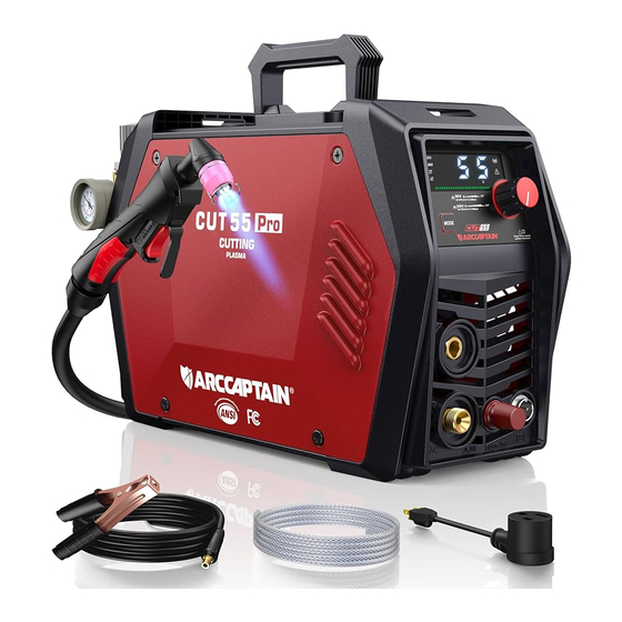
Dimensions(L*W*H) 17.8in*9.6in*6.1in/452*244*155mm Weight (lb) 11.5lb/5.2kg Figure 2: Size 2.3 Package Name Specification Quantity (pcs) Cutting machine CUT55 Pro Air Compressor Filter Installed on the machine Cutting torch & accessories AG-60 Ground clamp 200A-0.025in DKJ 10-25 Gas hose 0.3*0.47in Hose clamp Adapter 240V to 120V Strap... -
Page 9: Instructions
3. INSTRUCTIONS 3.1 Panel Instruction Part name Function Picture To display the cutting 1.Digital screen information 2.Operation For 2T/4T cutting mode mode button conversion 3.Earth cable To connect the earth cable terminal 4.Cutting torch To connect the cutting torch terminal 5.Current control To adjust the output current knob... -
Page 10: Nameplate
5.Strap hole To connect the strap * For more detailed information about the connection and operational guidelines for the ARCCAPTAIN APP, please visit arccaptain.com and explore the resources available there. 3.2 Nameplate On the machine, there is a plate that includes all the operating specifications for your new unit. -
Page 11: Installation And Connection
Figure 6: Nameplate 4.INSTALLATION AND CONNECTION ! WARINING BEWARE OF ELECTRIC SHOCK! Check and follow the instructions listed in the “Safety” section of this manual. ! WARINING DO NOT set up without SWITCH OFF ! 4.1 Installation of the cutting torch Check the torch for proper assembly. -
Page 12: Installation Of The Connection Cable
4.2 Installation of the Connection Cable ! WARINING DO NOT set up without SWITCH OFF ! Picture Description Connect the Cutting gun to “-” Negative polarity and aviation plug NOTICE: The Cutting gun connector MUST be tightly connected to the socket to avoid power short circuit. -
Page 13: Operation
Connection of input power The CUT55 PRO operates in 240V or 120V power supply. Plug the Power Cord into a properly grounded. Set Cutting Gun down on nonconductive, nonflammable surface away from any grounded objects. And then then turn the Power Switch ON. The fan should start. The Digital screen should turn on. -
Page 14: Operation Of The Reducer Valve
5.1 Operation of the reducer valve Picture Description Steps for reducer setting are as follows: lift the pressure control knob upward. adjust the gas pressure to the desired value by rotating the knob (rotate to “+” direction to increase gas pressure; rotate to “-”... -
Page 15: Operation Method
5.2 Operation method WARINING BEWARE OF ELECTRIC SHOCK! Description Picture 1. Confirm that cut55 has been installed and operated correctly, refer to sections 4 and 5 Figure 14 Installation 2. Clamp the Ground clamp onto the workpiece, The Ground clamp must securely connected workpiece. - Page 16 Figure 7 cutting torch head. If the accessories of cutting torch need to be replaced, please log in to the official website: WWW.ARCCAPTAIN.COM • Check the assembly of the torch consumables. If they are not properly in place, the machine will not start. Make sure that the shield cup is hand tight. Do not use pliers or over tighten.
-
Page 17: Notes For Cutting Operation
• Check the condition of the electrode. If the end has a crater-like appearance, replace it along with the nozzle. The maximum wear depth of the electrode is approximately .062”. A green and erratic arc will indicate definite electrode failure and the electrode should be replaced immediately. -
Page 18: Cutting Parameters Table
Keep the nozzle of cutting torch upright over the workpiece, and check if the arc is moving with the cutting line. If the space is not enough, don’t bend the cable too much, step on or press upon the cable to avoid suffocating of gas flow. -
Page 19: Replacement Of Electrode And Nozzle
Cutting speed declining, arc with green flame Difficult in arc ignition Irregular cut Figure 19 Exploded view of cutting torch If the accessories of cutting torch need to be replaced, please log in to the official website: WWW.ARCCAPTAIN.COM 6.MAINTENANCE WARINING BEWARE OF ELECTRIC SHOCK! NOTICE:... - Page 20 Tips: 1. Daily checking is very important in keeping the high performance and safe operation of this cutting machine. 2. Do daily checking according to the table below, and clean or replace components when necessary. 3. In order to ensure the high performance of the machine, please choose components provided or recommended by dealer when replacing components.
-
Page 21: Strap Installation
7.STRAP INSTALLATION Step 1: Thread the strap through the strap hole in front of the welder. Step 2: Thread the strap through the nylon buckle as shown in the diagram. Step 3: Thread the strap through the strap hole in back of the welder. Step 4: Thread the strap through the nylon buckle as shown in the diagram. -
Page 22: Troubleshooting
8. TROUBLESHOOTING WARINING BEWARE OF ELECTRIC SHOCK! The abnormity indicator on the front panel would illuminate in case of any failures inside the cutting machine. Cause and solution Malfunction phenomena Turn on the machine, the LED screen illuminates, the control PCB keys do The cutting machine crashes: Shut down the not function, and there is no response machine, and restart it. - Page 23 Appendix 1...
Need help?
Do you have a question about the 55 Pro and is the answer not in the manual?
Questions and answers
What type of 220v socket is required for arccaptain cux plasma cutter. Located in USA.
i have a arccaptain 55 pro and trying to run it on 120 volts it will come on then it will shut the flame off for no reason. is this because its not getting enough amps or what