
Related Manuals for Riello NXHM 04


Summary of Contents for Riello NXHM 04
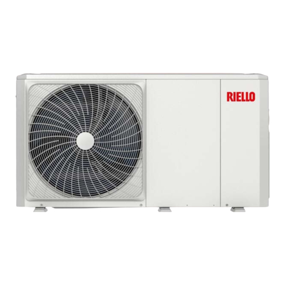
- Page 1 Riello Typical Installation with Third Party controls Installation and Setup Monobloc system February 2024...
-
Page 2: Table Of Contents
CONTENTS EASY NAVIGATION Introduction............................2 Warranty..............................3 Power Supplies..........................4 Control Wiring...........................6 Dip Switch Settings........................7 Pre commissioning Checks....................8 Controller Overview........................8 Starting Up the Unit for the First Time................9 Test Mode.............................11 Factory Reset...........................12 Putting the Unit into Operations..................12 Final Operational Checks.......................13 Fault Codes............................14 MCS & ENA............................15 CLICK ON THE TOPIC YOU WANT TO FIND OUT MORE INFORMATION... -
Page 3: Introduction
A strainer must be installed in the return pipeworkto the mono block this is included with the unit. It is strongly recommended by Riello in addition to this, a Magnetic filter and Flow setter should also be installed to the unit. -
Page 4: Warranty
Biocide, if not included in the heat transfer solution. Or an approved Anti Freeze device is used. A 25lt buffer is Recommended for the 4-10kw units and a 40lt for the 12-16kw Riello heat pumps, In order to meet the minimum system water open volume at all times. -
Page 5: Power Supplies
POWER SUPPLIES The Monobloc requires one Power supply, the details of the power supply are detailed below The above sizing are for guidance only, correct cable sizing should be undertaken by a suitably qualified engineer. All electrical connections should be completed by a NICEIC competent electrician www.seconrenewables.com 0191 516 6553 info@seconrenewables.com... - Page 6 Continued... If an immersion heater is installed to the DHW tank this should have its own independent supply. DO NOT supply directly from the PCB. This would require an additional 13amp supply and suitably sized cable. All supplies should be via a double switched isolator and all cables should be sized in accordance with BS7671 The Controller Requires a 5 core Screened cable.
-
Page 7: Control Wiring
CONTROL WIRING Below shows a basic wiring schematic for use with the previous hydralic schematic, for the Riello monobloc Heat pump. Using a Third party room stat for switching on and off the heating demand. Each terminal supplies a maximum of 0.2amp if the item connected draws more than 0.2amp a relay and a external supply should be used. -
Page 8: Dip Switch Settings
S1 Dip switch 1/2 should be set to OFF/OFF, this will deactivate the IBH (internal back up heater is not fitted to the Riello unit as standard) S1 Dip switch 3/4 should be set to OFF/OFF, this will deactivate the IBH and AHS... -
Page 9: Pre Commissioning Checks
PRE COMMISSONING CHECKS Before starting the unit, a number of pre checks that must be carried out. These can be found listed below. On the larger 12/14/16kw units there is a Transportation support bracket installed to the compressor within the unit, this bracket must be removed prior to starting the unit. -
Page 10: Starting Up The Unit For The First Time
STARTING UP THE UNIT FOR THE FIRST TIME When the monobloc is powered up for the first time, 1-100% will be displayed on the user interface during initialisation, in this time the controller can’t be used. The following setting must be entered into the controller these are detailed below, in order for the controller and Heat pump to operate correctly. - Page 11 Continued... Select Heat Mode Heat mode 3.1 Yes Set T1setH1 3.8, set to 55֯ c for Rads and 45֯ c for UFH or to the Design flow temp Set T1SetH2 3.9, set to 30֯ c Set T4H1 3.10, set to the External design temp We recommend -2֯...
-
Page 12: Test Mode
TEST MODE The unit can be put into a Test mode, this is done through the SERVICEMAN menu accessed as above. In the Test mode menu, there are a couple options that can be selected in this menu, these include testing of all Outputs. -
Page 13: Factory Reset
FACTORY RESET If at any point all the setting requires changing back to default, this can be done via the factory reset option. This can be selected in the SERVICEMAN menu, by selecting Restore Factory Settings. PUTTING THE UNIT INTO OPERATIONS In order to put the unit into operation you must turn on the modes within the home screen. -
Page 14: Final Operational Checks
Continued... FINAL OPERATIONAL CHECKS With the unit operating in Central Heating mode the mono bloc unit flow rate, can now be checked, to make sure the minimum flow rate is been achieved. 1. Enter SERVICEMAN menu as described in the previous sections. 2. -
Page 15: Fault Codes
Continued... FAULT CODES www.seconrenewables.com 0191 516 6553 info@seconrenewables.com... - Page 16 Continued... www.seconrenewables.com 0191 516 6553 info@seconrenewables.com...
-
Page 17: Mcs & Ena
MCS & ENA Please find below the product MCS Certification numbers. If further details on the Unit’s SCOP values are required at the designed flow temp, these can be found at Product directory - MCS (mcscertified.com) by searching the Certificate number below Below you can Find the ENA Database Registration Number and Maximum System Demand.
Need help?
Do you have a question about the NXHM 04 and is the answer not in the manual?
Questions and answers