Table of Contents
Advertisement
Quick Links
Advertisement
Table of Contents

Related Manuals for Autel MaxiSys MS909CV


Summary of Contents for Autel MaxiSys MS909CV
- Page 1 MaxiSys MS909CV...
- Page 2 Autel will not be liable for any direct, special, incidental, or indirect damages, or for any economic consequential damages (including lost profits) as a result of using this product.
-
Page 3: Safety Instructions
Safety Instructions The safety messages herein cover situations Autel is aware of at the time of publication. Autel cannot know, evaluate or advise you in regards of all possible hazards. You must be certain that any condition or service procedure encountered does not jeopardize your personal safety. - Page 4 DANGER When an engine is operating, keep the service area WELL VENTILATED or attach a building exhaust removal system to the engine exhaust system. Engines produce carbon monoxide, an odorless, poisonous gas that causes slower reaction time and can lead to serious personal injury or loss of life.
-
Page 5: Table Of Contents
CONTENTS ......................AFETY NFORMATION ......................AFETY NSTRUCTIONS 1 USING THIS MANUAL ....................1 ......................1 ONVENTIONS 2 GENERAL INTRODUCTION ..................3 ...................... 3 ABLET VCI ....................... 7 LASH BAS B200 ..................... 10 ....................11 CCESSORIES 3 GETTING STARTED ....................15 ...................... - Page 6 4.13 ....................58 IAGNOSTICS 5 SERVICE ........................60 ....................60 ESET ERVICE (EPB) S .............. 61 LECTRIC ARKING RAKE ERVICE (TPMS) S ........... 61 RESSURE ONITORING YSTEM ERVICE (BMS) S ............. 61 ATTERY ANAGEMENT YSTEM ERVICE (DPF) S ..............62 IESEL ARTICLE ILTER...
- Page 7 ....................... 84 ATTERY 8.10 ..................84 OUNTRY EGION 8.11 VID S ....................84 ETUP 8.12 ....................84 YSTEM ETTINGS 8.13 ....................... 85 BOUT 9 DATA MANAGER ......................86 ....................87 EHICLE ISTORY ..................89 ORKSHOP NFORMATION ......................90 USTOMER ........................90 MAGE ......................
- Page 8 15 MAXIVIDEO ........................ 103 16 QUICK LINK ....................... 104 17 REMOTE DESKTOP ....................105 17.1 ..................... 105 PERATIONS 18 USER FEEDBACK ..................... 107 19 AUTEL USER CENTER ..................... 108 20 MAINTENANCE AND SERVICE ................110 20.1 ................110 AINTENANCE NSTRUCTIONS 20.2 ................
-
Page 9: Using This Manual
Using This Manual This manual contains device usage instructions. Some illustrations shown in this manual may make reference to modules and optional equipment that are not included in your system. 1.1 Conventions The following conventions are used: 1.1.1 Bold Text Bold text is used to highlight selectable items such as buttons and menu options. - Page 10 Example: To power down the MaxiSys tablet Press and hold the Power/Lock button. Tap Power Off. Tap OK.
-
Page 11: General Introduction
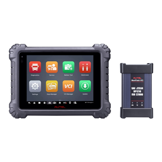
General Introduction MaxiSys MS909CV has three main components: MaxiSys Tablet — the central processor and monitor for the system. MaxiFlash VCI — vehicle communication interface. MaxiBAS B200 — battery & electrical system tester. This manual describes the construction and operation of these devices and how they work together to deliver diagnostic solutions. - Page 12 Table 2-1 Power LED Description Color Description Lights green when the tablet is charging and the battery level is above or equal to 90%. Green Lights green when the tablet is powered on and the battery level is above or equal to 15%. Power Lights yellow when the tablet is charging and the battery Yellow...
- Page 13 10. Headphone Jack 11. USB Port 12. USB Port 13. Mini USB Port 14. HDMI (High-Definition Multimedia Interface) Port 15. Micro SD Card Slot 16. DC Power Supply Input Port 17. Power/Lock Button — long press to turn the tablet on and off, or tap to lock the screen 2.1.2 Power Sources The tablet can receive power from any of the following sources:...
- Page 14 2.1.3 Technical Specifications Table 2-2 Tablet Specifications Item Description Operating System Android 10.0 Processor Octa-core processor (4 x 2.2 GHz + 4 x 1.8 GHz) Memory 4 GB RAM & 128 GB on-board memory 9.7-inch TFT-LCD capacitive touchscreen with 1536 Display x 2048 resolution ...
-
Page 15: Maxiflash Vci
Item Description −10 to 60 ° C (14 to 140 ° F) Storage Temp. 304.4 mm (11.98") x 227.8 mm (8.97") x 42.5 mm Dimensions ( W x H x D (1.67") 1.66 kg (3.66 lb.) Weight PLC J2497, ISO-15765, SAE-J1939, ISO-14229 UDS, SAE-J2411 Single Wire Can(GMLAN), ISO- 11898-2, ISO-11898-3, SAE-J2819 (TP20), TP16, ISO-9141, ISO-14230, SAE-J2610 (Chrysler SCI),... - Page 16 Vehicle LED Flashes green when communicating with the vehicle Connection LED Lights solid green when the VCI is connected via the USB cable Lights solid cyan when the VCI is connected via Wi-Fi Lights solid blue when the VCI is connected via Bluetooth Power LED ...
- Page 17 Vehicle Power AC/DC Power Supply 2.2.2.1 Vehicle Power The VCI operates on 12/24 Volt vehicle power, which receives power via the vehicle data connection port. The device powers on whenever it is connected to an OBDII/EOBD compliant Data Link Connector (DLC). For non OBDII/EOBD compliant vehicles, the device can be powered from an auxiliary power outlet adapter or other suitable power port on the test vehicle using the auxiliary power cable.
-
Page 18: Maxibas B200
2.3 MaxiBAS B200 2.3.1 Functional Description Figure 2-5 MaxiBAS B200 Device Power Button Status LED Power LED USB Port Battery Clamp Cable Aviation Plug Positive Clamp Cable Port Negative Clamp Cable Port... -
Page 19: Accessories Kit
2.4 Accessories Kit 2.4.1 Main Cable The MaxiFlash VCI can be powered through the Autel Main Cable V2.0 (the V2.0 icon can be seen on the cable) when connected to an OBDII/EOBD compliant vehicle. The Main Cable connects the VCI to the vehicle's DLC, through which the VCI can transmit vehicle data to the tablet. - Page 20 NOTE The MaxiFlash VCI can be connected by the Autel Main Cable V2.0 only. DO NOT use other Autel main cables to connect the MaxiFlash VCI. 2.4.2 Non-OBDII Adapters The adapter used depends on the type of vehicle being tested. The most common adapters are shown below.
- Page 21 2.4.3 Other Accessories AC/DC Adapter (12V) Connects the tablet to the external DC power port for power supply. USB 2.0 Cable V2 Connects the tablet to the VCI. Type-C USB Cable Connects the tablet to the PC. Clamp Cable Provides power to the tablet or the VCI through connection to the vehicle battery.
- Page 22 OBDII Extension Cable Used to connect the vehicle’s DLC and an adapter to extend the length of the cable. 400A Current Clamp Used to measure AC or DC current up to 400A. Multimeter Test Lead x2 Used to connect the multimeter and multimeter probe. Alligator Clip x2 Designed for connecting exposed wires or terminals.
-
Page 23: Getting Started
Getting Started Make sure the tablet has sufficient power or is connected to the external power supply (see Power Sources). NOTE The images and illustrations depicted in this manual may differ from the actual ones. 3.1 Power Up Long press the Power/Lock button on the top-right side of the tablet to switch the unit on. - Page 24 Almost all operations on the tablet are controlled through the touchscreen. The touchscreen navigation is menu-driven, which allows you to quickly locate the test procedure, or data that you need, through a series of questions and options. Detailed descriptions of the menu structures are found in the chapters for each application. 3.1.1 Application Buttons The table below briefly describes each of the applications in the MaxiSys system.
- Page 25 Allows you to submit feedback related to this User Feedback product. See User Feedback for details. Allows you to register an Autel account, view Autel User and edit your personal profile, and link your Center device. See Autel User Center for details.
- Page 26 Button Name Description Back Returns to the previous screen. MaxiSys Returns to MaxiSys Job Menu. Home Android Returns to the Android system home screen. Home Displays a list of currently running applications. Recent Tap an app icon to launch. To remove an app, Apps swipe it to the left or right.
-
Page 27: Power Down
NOTE After swiping the camera screen from left to right, the camera mode and video mode can be switched by tapping the blue camera icon or video icon. 3.1.3 System Status Icons These are the standard status icons of the Android operating system. Your MaxiSys tablet is a fully functional Android Pad. -
Page 28: Cv Diagnostics Operations
Connect the VCI to the tablet via Bluetooth pairing, Wi-Fi or USB connection. Check the VCI navigation button at the bottom bar on the screen. If a green BT, Wi- Fi or USB icon appears at the lower-right corner, the MaxiSys MS909CV Diagnostics Platform is ready to start vehicle diagnosis. - Page 29 Connect the cable's 16-pin male adapter to the vehicle's DLC, which is generally located under the vehicle dashboard. NOTE The vehicle's DLC is not always located under the dashboard. Refer to the user manual of the test vehicle for additional connection information. Non-OBDII Vehicle Connection This type of connection requires both the main cable V2.0 and a Deutsch-9/Deutsch- 6/UNI-4 adapter for the specific vehicle being serviced.
- Page 30 Figure 4-1 Connect Auxiliary Power Outlet Adapter to Clamp Cable Plug the DC power connector of the auxiliary power outlet adapter into the DC power supply input port of the VCI. Connect the clamp cable to the vehicle's battery. NOTE After the VCI is successfully connected to the vehicle, the Power LED on the VCI lights, and a beeping sound will be heard.
- Page 31 NOTE If no VCI is found, this may indicate that the signal strength is too weak to be detected. Reposition the VCI and remove all possible objects that may cause signal interference. Tap the Scan button at the top-right corner to rescan for the VCI. Typically, the VCI name appears as “Maxi”...
- Page 32 4.1.1.3 No Communication Message A. If the tablet is unable to connect to the VCI, an error message appears. An error message indicates the tablet is not communicating with the VCI. Troubleshoot the error by performing the following steps: Ensure the VCI is powered on.
- Page 33 4.1.2.1 Vehicle Menu Layout When the VCI is properly connected to the vehicle and paired to the tablet, the platform is ready to start vehicle diagnosis. Tap the Diagnostics application on the MaxiSys Job Menu, the Vehicle Menu displays on the screen. Figure 4-2 Vehicle Menu Screen Top Toolbar Buttons CV Band Vehicles...
- Page 34 4.1.3.1 Auto Detect The MaxiSys MS909CV diagnostics system features the latest VIN-based Auto VIN Scan function to identify the test vehicle with just one tap, enabling the technician to quickly identify the exact vehicle and scan its available systems for fault codes.
- Page 35 Figure 4-3 Auto Detect Screen In some cases, the Auto VIN function is still available for some vehicle makes after being selected. Select an automobile manufacturer icon from the Vehicle Menu screen (Figure 4-2) and then tap Automatic Selection > Read. The system will proceed to acquire VIN information automatically or allow users to manually enter the VIN.
- Page 36 To perform Manual Input Tap the Diagnostics application button from the MaxiSys Job Menu. The Vehicle Menu displays. Tap the VID button on the top toolbar. Select Manual Input (Figure 4-3). Tap the input box and enter the correct VIN code or license number. Tap OK.
-
Page 37: Diagnostics Screen Layout
Figure 4-5 Scan VIN Code Screen If the VIN/license number cannot be scanned, please manually enter it after tapping the pen-shape icon. Tap OK to continue. Manually enter the license number and select a vehicle brand in the Vehicle Information Confirmation screen. - Page 38 commonly used, including Auto Scan and Control Unit. The available functions displayed vary by vehicle. Figure 4-6 Main Menu Screen Diagnostics Toolbar Current Directory Path Status Information Bar Main Section Function Buttons Diagnostics Toolbar The Diagnostics Toolbar contains buttons that allow you to print or save the displayed data and perform other operations.
- Page 39 Button Name Description Provides instructions or tips for operations of various Help diagnostics functions. Save Opens a submenu which provides options for data storage. Records the communication data and ECU information of the vehicle. The saved data can be reported and sent to Data the technical center via the Internet.
- Page 40 Current Directory Path The Directory Path shows all directory names to access the current page. Status Information Bar The Status Information Bar at the top of the Main Section displays the following items: Network Icon — indicates whether a network is connected. VCI Icon —...
-
Page 41: Auto Scan
Error Messages These appear when a system or procedural error has occurred. Examples of possible errors include a disconnected cable or communication interruption due to certain reasons. 4.2.2 Making Selections The diagnostics application is a menu-driven program that presents a series of choices one at a time. - Page 42 Figure 4-7 Auto Scan Screen NOTE On the Auto Scan screen, there is a Select System icon ( ) on the upper-right corner. Select the corresponding system(s) to scan, saving more time than scanning all systems. The results are displayed on the screen. 4.3.1 Auto Scan Results A.
- Page 43 Figure 4-8 Topology Screen B. List Screen Column 1 — displays the system numbers. Column 2 — displays the scanned systems. Column 3 — displays the scan results. Fault | #: Indicates there is/are fault code(s) present; “#” indicates the quantity of detected faults.
-
Page 44: Control Unit
Name Description Pause Pauses the scanning process. Enter System Enters the ECU system. Returns to the previous screen or exits the Diagnostics screen. Select one of the system modules from the Topology or List screen and tap Enter System to enter the specific system functions. 4.4 Control Unit The Control Unit function allows you to manually locate a required control system for testing through a series of choices. -
Page 45: Ecu Information
Figure 4-9 Function Menu Screen 4.5 ECU Information This function retrieves and displays the specific information for the tested control unit, including unit type and version numbers. Figure 4-10 ECU Information Screen Diagnostics Toolbar Buttons — see The Diagnostics Toolbar contains buttons that allow you to print or save the displayed data and perform other operations. -
Page 46: Trouble Codes
Main Section — the left column displays the item names; the right column displays the specifications or descriptions. Function Button — in this case, only the ESC button is available. Tap it to exit after viewing. 4.6 Trouble Codes 4.6.1 Read Codes This function retrieves and displays DTCs from the vehicle control system. -
Page 47: Live Data
viewing; Tap to display data screen. The Freeze Frame interface is similar to that of the Read Codes interface and shares similar operations. Search — searches the selected DTC for additional information on the Internet. Erase Codes — erases codes from the ECU. It is recommended that DTCs are ... - Page 48 Figure 4-12 Live Data Screen Diagnostics Toolbar Buttons — see Table 4-2 Diagnostics Toolbar Buttons detailed descriptions of the operations of each button. Main Section Name Column — displays the parameters. Check Box — tap the check box to the left of a parameter to select the item. Tap the check box again to deselect it.
- Page 49 Figure 4-13 Display Mode Screen Each parameter displays the selected mode independently. Analog Gauge Mode — displays the parameters in gauge charts. Text Mode — default displays the parameters as a text list. NOTE Some status parameters, such as a switch reading like ON, OFF, ACTIVE, and ABORT, can only be displayed in Text Mode.
- Page 50 Settings Button (SetY) — sets the minimum and maximum value of the Y-axis. Scale Button — changes the scale values. There are two scale buttons, displayed above the waveform graph to the right side, which can be used to change the scale values of the X-axis and Y-axis of the graph. There are four scales available for the X-axis: x1, x2, x4 and x8, and three scales available for the Y-axis: x1, x2, and x4.
- Page 51 Figure 4-15 Waveform Edit Screen The selected parameter is shown automatically in the left column. Select a color from the second column. Select a line thickness from the right column. Tap Done to save the settings and exit, or tap Cancel to exit without saving. NOTE In full screen display mode, you can edit the waveform color and line thickness by tapping the Edit button on the top-right side of the screen.
- Page 52 value. The buzzer alarm will only sound at the first trigger. MIN — tap this input box to display a virtual keyboard to enter a lower threshold value. MAX — tap this input box to display a virtual keyboard to enter an upper threshold value.
- Page 53 To merge selected data graphs Select parameters to be merged. Tap the Graph Merge button at the bottom of the Live Data screen. This mode only supports parameters that can be represented digitally. If non-digital parameters are selected, a message will display advising the user that the selected parameters are not supported in this mode and to select 2 to 5 digital parameters.
- Page 54 Next Frame — moves to the next frame of frozen data. Play/Pause — tap to play/pause the frozen data. Resume — tap to exit the freeze data mode and return to normal data display. Record — starts recording the live data of the selected data. Tap the Record button at the bottom of the Live Data screen.
-
Page 55: Active Test
4.8 Active Test The Active Test function is used to access vehicle-specific subsystem and component tests. Available tests vary by vehicle. During an active test, the tablet sends commands to the ECU to activate the actuators. This test determines the integrity of the system or part by reading ECU data or by monitoring the operation of the actuators. -
Page 56: Programming And Coding
4.10 Programming and Coding Since the introduction of OBDII and leading up to modern hybrids and EVs, hardware and software technologies in cars have been advancing at an exponential rate. Updating software may be the only way to fix the following issues: ... - Page 57 programming interface or opens another menu of additional choices. Follow all screen instructions while performing the programming or coding operations. How and what information is presented on the screen vary by the type of operation being performed. 4.10.1 Coding The main section of the Coding screen displays a list of vehicle components and the coding information that mainly consists of two parts: All available systems for coding are displayed on the left side, and the coding data or value on the right side.
-
Page 58: Generic Obdii Operations
A series of on-screen operational instructions will display to guide you through the programming procedure. Carefully read the on-screen information and follow the instructions to execute the programming procedure. 4.10.3 Re-flash Errors IMPORTANT When reprogramming onboard, always make sure the vehicle battery is fully charged and in good working condition. - Page 59 order to determine which one the vehicle is using. Protocol — select to open a submenu of various protocols. A communication protocol is a standardized way of data communication between an ECM and a diagnostics tool. Global OBD may use several different communication protocols.
- Page 60 4.11.2 Function Descriptions This section describes the various functions of each diagnostics option: 4.11.2.1 DTC & FFD When this function is selected, the screen displays a list of Current Codes and Pending Codes. When the Freeze Frame data of certain DTCs are available for viewing, a snowflake icon will display on the right side of the DTC item.
- Page 61 A confirmation screen displays when the clear codes option is selected to prevent accidental loss of data. Select Yes on the confirmation screen to continue, or No to exit. 4.11.2.2 I/M Readiness This function is used to check the readiness of the monitoring system. It is an excellent function to use prior to having a vehicle inspected for state emissions compliance.
-
Page 62: Diagnostics Report
4.11.2.8 Vehicle Status This function checks the current condition of the vehicle, such as the communication protocols of OBDII modules, number of fault codes, and status of the Malfunction Indicator Lamp (MIL). 4.12 Diagnostics Report 4.12.1 Pre-scan and Post-scan After performing pre-scan and post-scan functions by entering the same maintenance order number, tap Data Manager >... - Page 63 4.12.2.1 Diagnostics Report Saving Via the History function: Enter the main screen of the Diagnostics application, and tap History on the top toolbar. Figure 4-19 History Screen Select a history record and tap the ellipses button in the upper-right corner. Figure 4-20 Historical Test Screen Tap View PDF to view the report directly.
- Page 64 Enter the Auto Scan page and tap Fault Scan in the Function Button Bar at the bottom of the screen. Figure 4-21 Auto Scan Screen Sample 1 When the system scan is completed, tap Report in the Function Button bar at the bottom of the screen.
- Page 65 PDF to view these local reports. Once you save the reports by tapping the Get Report or Report to Cloud button, tap Data Manager > Cloud Report to view these reports saved to the Autel cloud platform. 4.12.2.3 Diagnostic Report Sharing...
-
Page 66: Exit Diagnostics
Figure 4-24 Report List Screen NOTE Note that if the report displays , it means the report has been uploaded to the cloud successfully, and you can share the report with others; if the report displays , it means the report has failed to upload to the cloud, but will try to automatically upload to the cloud when entering the Report again. - Page 67 Or tap Vehicle Swap button in the diagnostics toolbar to return to the Vehicle Menu screen. On the Vehicle Menu screen Tap the Home button in the top toolbar. Or tap the Back button in the navigation bar at the bottom of the screen. Or tap the Home button in the diagnostics toolbar to exit the application directly and return to the MaxiSys Job Menu Now, the Diagnostics application is no longer communicating with the vehicle and it is...
-
Page 68: Service
Service The Service section is specially designed to provide quick access to the vehicle systems for various scheduled service and maintenance tasks. The typical service operation screen is a series of menu-driven commands. Follow the on-screen instructions to select appropriate options, enter values or data, and perform necessary actions. The application will display detailed instructions to complete selected service operations. -
Page 69: Electric Parking Brake (Epb) Service
Ensure that the EPB control system is reactivated after the maintenance work has been completed. NOTE Autel accepts no responsibility for any accident or injury arising from the maintenance of the Electric Parking Brake system. 5.3 Tire Pressure Monitoring System (TPMS) Service... -
Page 70: Diesel Particle Filter (Dpf) Service
state, monitor the close-circuit current, register the battery replacement, activate the rest state of the vehicle, and charge the battery via the diagnostics socket. NOTE This function is not supported by all vehicles. The sub functions and actual test screens of the BMS may vary by vehicle, please follow the on-screen instructions to make correct option selection. -
Page 71: Immobilizer (Immo) Service
IMPORTANT Before diagnosing the problem vehicle and attempting to perform an emergency regeneration, it is important to obtain a full diagnostics log and read out relevant measured value blocks. NOTE The DPF will not regenerate if the engine management light is on, or there is a faulty EGR valve. -
Page 72: Steering Angle Sensor (Sas) Service
Accident repairs where damage to the SAS, SAS assembly, or any part of the steering system may have occurred NOTE Autel accepts no responsibility for any accident or injury arising from servicing the SAS system. When interpreting DTCs retrieved from the vehicle, always follow the manufacturer's recommendation for repair. ... -
Page 73: Battery Test
6.1.2 Connect the Battery Tester To pair the B200 with the MaxiSys MS909CV tablet Press and hold the Power button to turn on the MS909CV and MaxiBAS B200 battery tester. Ensure that each unit is sufficiently charged before use. -
Page 74: In-Vehicle Test
the tablet automatically scans for an available tester for pairing. The device name will appear as “Maxi” suffixed with a serial number. Check the serial number of your battery tester and select the desired device for pairing. When paired successfully, the connection status will read as “Connected” and the Status LED will flash blue. - Page 75 IMPORTANT A disclaimer page will appear when accessing any function on the Home screen for the first time. Please read the end user agreement and tap Accept to continue. If you tap Decline, you will not be able to use the features properly. NOTE The complete in-vehicle test includes battery test, starter test and generator test, in sequence.
- Page 76 Figure 6-3 Battery information Screen Please refer to the table below for a list of buttons that may appear when accessing the functions: Table 6-1 Top Toolbar Buttons Button Name Description The value on the icon indicates the real-time voltage of Battery the tested battery.
- Page 77 Figure 6-4 Battery Test Screen Wait until the test is completed. The test results will be displayed on the tablet. Figure 6-5 Battery Test Results Screen Battery Test Results The battery test results include a color-coded results summary and a list of test data.
- Page 78 Table 6-2 Battery Test Results Result Description Good Battery Battery is good. Good & Recharge Battery is good but insufficiently charged. Recharge the battery. Charge & Retest Battery requires charge to determine its condition. Bad Cell Replace the battery. Replace Battery Replace the battery.
- Page 79 6.2.4 Generator Test Follow the on-screen instructions to complete the test. The test results will appear as follows: Figure 6-7 Generator Test Results Screen Table 6-4 Generator Test Results Result Description Charging Normal The generator is functioning normally. The belt linking the starter and the generator is loose;...
-
Page 80: Out-Vehicle Test
NOTE To measure the current, connect the current clamp. Tap the Settings button on the main menu to enter the application. Swipe the Current Clamp toggle to turn it ON. 6.3 Out-vehicle Test Out-vehicle Test is used to test the conditions of batteries that are not connected to a vehicle. - Page 81 Figure 6-9 Out-vehicle Test Results Screen 6.3.2 Test Results Icons are color-coded to indicate status. Table 6-5 Out-vehicle Test Results Result Description Good Battery Battery meets required standards. Battery is good, but low on charge. Fully charge the Good & Recharge battery.
-
Page 82: Multimeter
Multimeter The DM100 digital multimeter is a multi-function, multi-range measuring instrument. Connect the multimeter to the B200 device and access its features directly from the MaxiSys 909CV Job Menu screen to perform basic functions including AC/DC voltage, resistance measurements, AC/DC current, diode, and connectivity tests. The test results are displayed in various formats for easy viewing. -
Page 83: Connecting The Multimeter
the circuit. Remember to place the multimeter in series with the circuit. After current measurement is finished, turn off the power to the circuit before removing the test leads and before reconnecting any disconnected wires or devices. Do not add voltage to the input terminal when measuring resistance. ... -
Page 84: Screen Layout And Operations
Connect the multimeter to the multimeter cable port of the MaxiBAS B200 Series Tester and tighten the connector of the multimeter. Now you can start to perform basic functions including AC/DC voltage, resistance measurements, AC/DC current, diode, and connectivity tests. Access the test results directly from the MaxiSys 909CV Job Menu screen. - Page 85 Figure 7-1 Multimeter Screen Upper Toolbar Icon Description Name MaxiSys Returns to the MaxiSys Job Menu. Home Starts or stops the multimeter device. Tap Start/Stop start the multimeter. Tap to stop the multimeter. Indicates the connection status with the battery tester.
- Page 86 Average: the average value of the measurements. The waveform in the grid: a coordinate grid with the X-axis representing the time duration and the Y-axis representing the amplitude level. Lower Toolbar to select the measurement types you want: Description Icon Name...
-
Page 87: Settings
Settings Access the Settings menu to adjust default settings and view information about the MaxiSys system. Figure 8-1 Settings Screen The following options are available for the MaxiSys system settings: Unit Language Printing Settings Report Settings ... -
Page 88: Unit
8.1 Unit This option allows you to change the units of measurement for the diagnostics system. To change the unit setting Tap the Settings application on the MaxiSys Job Menu. Tap the Unit option on the left column. Select the appropriate units of measurement. A check mark displays to the right of the selected unit. -
Page 89: Report Settings
To install the MaxiSys Printer driver Download Maxi PC Suite from www.autel.com > Support > Downloads > Autel Update Tools, and install to your Windows-based PC. Double-click on Setup.exe. Select an installation language to launch the installation wizard. Follow the instructions on the screen and click on Next to continue. -
Page 90: Push Notifications
Scan Report: Toggle the ON/OFF button to enable/disable the Repair Diagnostics Report function. The Repair Diagnostics Report function includes the diagnosis reports before and after the diagnosis. Once the Repair Diagnostics Report function is enabled, you can enter the service order number in the Select Test Type box after tapping on a vehicle manufacturer to build a repair task, then perform the diagnostic scan. -
Page 91: Auto Update
MaxiSys MS909CV is bound to the main frame when it leaves the factory, and you can configure related settings through the following steps: ... -
Page 92: Battery Test
8.9 Battery Test To adjust the battery test settings Tap the Settings application on the MaxiSys Job Menu. Tap the Battery Test option on the left column. Switch on Current Clamp and then you can measure the current when doing the battery test. -
Page 93: About
8.13 About The About function provides information about the MaxiSys diagnostics device, including the product name, version, hardware, and serial number. To check the MaxiSys product information in About Tap the Settings application on the MaxiSys Job Menu. Select the About option on the left column. The product information displays on the right. -
Page 94: Data Manager
Data Manager The Data Manager application allows you to store, print, and review the saved files, manage the workshop information, customer information records, and keep test vehicle records. Selecting the Data Manager application opens the file system menu. There are nine main functions available. -
Page 95: Vehicle History
Description View the diagnostics reports. Review Data View recorded data. View communications with Autel support service and ECU information of the test vehicle. The Data Logging saved data can be reported and sent to the technical center via the Internet. - Page 96 Select Vehicle History to open the screen. Tap Diagnostics, Service or Battery Test to select diagnostics test records or service test records. Tap the icon at the bottom of the thumbnail of a vehicle record. The diagnostics screen of the vehicle appears and a new diagnostic session is activated.
-
Page 97: Workshop Information
Tap Add a Customer to correlate the historical Records sheet to an existing customer account, or add a new account to be correlated with the test vehicle record. See Customer for more information. Tap Done to save the updated record, or tap Cancel to exit without saving. NOTE The vehicle VIN, license number, and customer account are correlated by default. -
Page 98: Customer
9.3 Customer The Customer function allows you to create and edit customer accounts. It helps you to save and organize all customer accounts correlated with the test vehicle history records. To create a customer account Tap the Data Manager application in the MaxiSys Job Screen. Select Customer. - Page 99 Figure 9-5 Image Database Screen Toolbar Buttons — used to edit, print or delete stored image files. See Table 9-2 Toolbar Buttons Description or detailed information. Main Section — displays the stored images. Table 9-2 Toolbar Buttons Description Button Name Description Back Return to the previous screen.
-
Page 100: Cloud Report
Tap Email to send the selected image(s) to an email. 9.5 Cloud Report This section displays the saved reports, which can be transferred to the Autel cloud platform once a stable network connection is established. These reports can then be viewed or shared with others. -
Page 101: Data Logging
Main Section — displays the recorded data frames. Navigation Toolbar — allows you to manipulate data playback. Use the Navigation Toolbar buttons to play back the record data from frame to frame. Tap Back to exit data playback. 9.8 Data Logging The Data Logging section allows you to launch the Support platform to view records of all feedback or not feedback (saved) data logs on the diagnostics system. -
Page 102: Vci Manager
VCI Manager VCI Manager is for connecting the MaxiSys MS909CV tablet with a VCI through Wi-Fi or Bluetooth. This application allows you to pair the tablet with the VCI and to check its communication status. Figure 10-1 VCI Manager Screen 10.1 VCI Connection via Wi-Fi... -
Page 103: Vci Connection Via Bluetooth
NOTE If no VCI is found, this may indicate that the signal strength is too weak to be detected. Reposition the VCI and remove all possible objects that may cause signal interference. Tap the Refresh button at the top-right corner to rescan for the VCI. Depending on the VCI type you use, the device name may display as “Maxi”... -
Page 104: Bas Connection Via Bluetooth
To pair the B200 series tester with the tablet Power on the MaxiSys MS909CV and the MaxiBAS B200. Enable Bluetooth on the MS909CV by tapping VCI Manager > BAS BT, and the tablet automatically scans for available testers for pairing. The device name will appear as “Maxi”... -
Page 105: Update
Internet. Any updates that are found can be downloaded and installed on the tablet with a stable Internet connection. NOTE Make sure the tablet is registered before activating the Update application. See Autel User Center for details. ... -
Page 106: Support
Support This application launches the Support platform which synchronizes Autel's online service base station with the MaxiSys tablet. Connected to Autel's service channel and online communities, the Support application provides the quickest way for problem solutions, allowing you to send help requests to obtain direct service and support. -
Page 107: Training
The Service Info section displays a detailed record list of the device's service history information. Every time the device has been sent back to Autel for repair, the device's serial number and other information, such as the fault type, changed components, or system reinstallation will be recorded and updated to the associated online product account that will be synchronized to the Service Info section. -
Page 108: Faq Database
12.5 FAQ Database The FAQ section provides comprehensive references for all questions frequently asked and answered about the use of Autel's online member account, shopping, and payment procedures. Account — displays questions and answers about the use of Autel's online user ... -
Page 109: Maxiviewer
MaxiViewer MaxiViewer allows you to search the functions supported by our tools and the version information. There are two ways of searching, either by searching the tool and the vehicle or searching the functions. To search by vehicle Tap the MaxiViewer application on the MaxiSys Job Menu. Tap the tool name on the top-left to drop down the tool list, and tap the one you want to search. -
Page 110: Adas Filter
ADAS Filter This The ADAS Filter application enables you to achieve the specified ADAS calibration by selecting product type, calibration mode, vehicle’s brand, mode, year, and so on. When you need to calibrate some of the vehicle systems, you can use the ADAS Filter application to filter, no need to perform the whole ADAS calibration procedures any more. -
Page 111: Maxivideo
MaxiVideo The MaxiVideo application configures the MaxiSys tablet to operate as a digital video scope by simply connecting the tablet to a MaxiVideo camera. This function allows you to examine difficult-to-reach areas normally hidden from sight, with the ability to record digital still images and videos, which offers you an economical solution to inspect machinery, facilities, and infrastructure in a safe and quick way. -
Page 112: Quick Link
Quick Link The Quick Link application provides you with convenient access to Autel's official website and many other well-known sites in automotive service, which offers you abundant information and resources, such as technical help, knowledge bases, forums, training, and expert consultations. -
Page 113: Remote Desktop
You can use the application to receive ad-hoc remote support from Autel's support center, colleagues or friends, by allowing them to control your MaxiSys tablet on their PC via the TeamViewer software. - Page 114 (http://www.teamviewer.com). Start the software on their computer at the same time in order to provide support and take control of the tablet remotely. Provide your ID to the partner, and wait for them to send you a remote control request. A message displays to ask for your confirmation to allow remote control on your device.
-
Page 115: User Feedback
PDF files with the form. To help resolve the issue efficiently, we recommend you to complete the form with as many details as possible. Tap Submit to send the completed form to Autel's online service center. The submitted feedback will be carefully read and handled by our support personnel. -
Page 116: Autel User Center
Figure 19-1 Autel User Center Screen If you already have an Autel ID, you can log in with your phone number and verification code, or tap Log In with Password to log in with your Autel ID and password. If you do not have an Autle ID yet, tap Register to create an Autel Once your account is successfully registered, you will enter the main menu of the Autel User Center. - Page 117 Visit the website: pro.autel.com. If you have an Autel account, log in and skip to Step 7. If you are a new member to Autel, click Register to create your Autel ID. Enter your personal information. Fields marked with an asterisk (*) are mandatory.
-
Page 118: Maintenance And Service
Maintenance and Service To ensure that the tablet and the combined VCI unit perform at their optimum level, we advise that the product maintenance instructions in this section are strictly followed. 20.1 Maintenance Instructions The following includes instructions on how to maintain your devices, together with precautions to take. -
Page 119: About Battery Usage
Your device may not be connected to the charger properly. Check the connector. NOTE If the problems persist, please contact Autel's technical support personnel or your local selling agent. 20.3 About Battery Usage Your tablet is powered by a built-in lithium-ion polymer battery, which enables you to recharge your battery when there is electricity left. -
Page 120: Service Procedures
This section provides information on technical support, repair service, and application for replacement or optional parts. 20.4.1 Technical Support If you have any question or problem on product operations, please contact us. Autel China Headquarters Phone: +86 (0755) 8614-7779 (Monday-Friday, 9AM-6PM Beijing Time) ... - Page 121 Email: imea-support@autel.com Address: 906-17, Preatoni Tower (Cluster L), Jumeirah Lakes Tower, DMCC, Dubai, Web: www.autel.com Autel Latin America Mexico: Phone: +52 33 1001 7880 (Spanish in Mexico) Email: latsupport@autel.com Address: Avenida Americas 1905, 6B, Colonia Aldrete, Guadalajara, Jalisco, Mexico...
- Page 122 Floor 2, Caihong Keji Building, 36 Hi-tech North Six Road, Songpingshan Community, Xili Sub-district, Nanshan District, Shenzhen City, China 20.4.3 Other Services You can purchase the accessories directly from authorized tool suppliers of Autel, or your local distributor or agent. Your purchase order should include the following information: ...
-
Page 123: Compliance Information
Compliance Information FCC Compliance FCC ID: WQ8-MS909DV2125 This equipment has been tested and verified to comply with the limits for a Class B digital device, pursuant to Part 15 of the FCC Rules. These limits are designed to provide reasonable protection against harmful interference in a residential installation. This equipment generates uses and can radiate radio frequency energy and, if not installed and used in accordance with the instructions, may cause harmful interference to radio communications. - Page 124 RF WARNING STATEMENT The device has been evaluated to meet general RF exposure requirement. The device can be used in portable exposure condition without restriction. RoHS COMPLIANCE This device is declared to be in compliance with the European RoHS Directive 2011/65/EU.
-
Page 125: Warranty
Warranty 22.1 12-month Limited Warranty Autel Intelligent Technology Corp., Ltd. (the Company) warrants to the original retail purchaser of this MaxiSys diagnostics device that should this product or any part thereof during normal usage and under normal conditions be proven defective in material or...
Need help?
Do you have a question about the MaxiSys MS909CV and is the answer not in the manual?
Questions and answers