Table of Contents
Advertisement
Quick Links
Trademarks
®
®
Autel
, MaxiSys
, MaxiDAS
are trademarks of Autel Intelligent Technology Corp., Ltd., registered in China, the United
States and other countries. All other marks are trademarks or registered trademarks of their
respective holders.
Copyright Information
No part of this manual may be reproduced, stored in a retrieval system or transmitted, in any
form or by any means, electronic, mechanical, photocopying, recording, or otherwise without
the prior written permission of Autel.
Disclaimer of Warranties and Limitation of Liabilities
All information, specifications and illustrations in this manual are based on the latest
information available at the time of printing.
Autel reserves the right to make changes at any time without notice. While information of
this manual has been carefully checked for accuracy, no guarantee is given for the
completeness and correctness of the contents, including but not limited to the product
specifications, functions, and illustrations.
Autel will not be liable for any direct, special, incidental, indirect damages or any economic
consequential damages (including lost profits).
IMPORTANT
Before operating or maintaining this unit, please read this manual carefully, paying extra
attention to the safety warnings and precautions.
For Services and Support:
pro.autel.com
www.autel.com
1-855-288-3587/1-855-AUTELUS (North America)
0086-755-86147779 (China)
support@autel.com
For details, please refer to the
®
®
, MaxiScan
, MaxiTPMS
Service Procedures
i
®
, MaxiRecorder
in this manual.
®
®
, and MaxiCheck
Advertisement
Table of Contents

Related Manuals for Autel MaxiSys MS909CV


Summary of Contents for Autel MaxiSys MS909CV
- Page 1 All information, specifications and illustrations in this manual are based on the latest information available at the time of printing. Autel reserves the right to make changes at any time without notice. While information of this manual has been carefully checked for accuracy, no guarantee is given for the completeness and correctness of the contents, including but not limited to the product specifications, functions, and illustrations.
-
Page 2: Safety Messages
Safety Instructions The safety messages herein cover situations Autel is aware of. Autel cannot know, evaluate or advise you in regards of all possible hazards. You must be certain that any condition or... -
Page 3: Safety Warnings
DANGER When an engine is operating, keep the service area WELL VENTILATED or attach a building exhaust removal system to the engine exhaust system. Engines produce carbon monoxide, an odorless, poisonous gas that causes slower reaction time and can lead to serious personal injury or loss of life. -
Page 4: Table Of Contents
CONTENTS ......................AFETY NFORMATION Safety Messages ....................... ii ...................... AFETY NSTRUCTIONS Safety Warnings ....................... iii 1 USING THIS MANUAL ...................... 1 1.1 C ......................1 ONVENTIONS 1.2 B ......................... 1 1.2.1 Notes and Important Messages ................. 1 1.2.2 Hyperlink ......................2 1.2.3 Illustrations ...................... - Page 5 4.1 E ..........21 STABLISH EHICLE OMMUNICATION AND ELECTION 4.1.1 Establish Vehicle Communication ..............21 4.1.2 Getting Started ....................25 4.1.3 Vehicle Identification ..................27 4.2 D ................... 32 IAGNOSTICS CREEN AYOUT 4.3 A ....................... 33 4.4 C ......................38 ONTROL 4.4.1 Screen Messages ....................
- Page 6 5.2.2 Technical Service Bulletin (OEM Information)..........76 5.2.3 DTC Analysis ....................77 6 SERVICE ......................... 78 6.1 O ....................78 ESET ERVICE 6.2 A ..................79 FTERTREATMENT ERVICE 6.3 L ......................80 IMIT ERVICE 6.4 I ....................80 NJECTOR ERVICE 6.5 S &...
- Page 7 9.10 S ....................100 YSTEM ETTINGS 9.11 A ........................100 BOUT 10 DATA MANAGER ......................101 10.1 V ....................102 EHICLE ISTORY 10.1.1 Test Records ....................103 10.2 W ..................104 ORKSHOP NFORMATION 10.3 C ......................105 USTOMER 10.4 I ........................
- Page 8 15.1.4 Technical Specifications ................126 15.2 O ......................127 PERATIONS 16 QUICK LINK ........................ 129 17 REMOTE DESKTOP ....................130 17.1 O ......................130 PERATIONS 18 USER FEEDBACK ...................... 132 19 MAINTENANCE AND SERVICE ................. 133 19.1 M ................. 133 AINTENANCE NSTRUCTIONS 19.2 T...
-
Page 9: Using This Manual
Using This Manual This manual contains device usage instructions. Some illustrations shown in this manual may contain modules and optional equipment that are not included in your system. 1.1 Conventions The following conventions are used. 1.2 Bold Text Bold text is used to highlight selectable items such as buttons and menu options. Example: ... -
Page 10: Hyperlink
1.2.2 Hyperlink Hyperlinks or links that take you to other related articles, procedures, and illustrations are available in electronic documents. Blue italic text indicates a selectable hyperlink and blue underlined text indicates a website link or an email address link. 1.2.3 Illustrations Illustrations used in this manual are samples, and the actual testing screen may vary for each vehicle being tested. -
Page 11: General Introduction
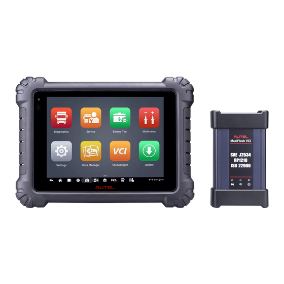
General Introduction MaxiSys MS909CV provides the full functionality and online repair information you need when diagnosing vehicles, identifying faults and researching repair issues. It features a powerful octa-core processor and 9.7-inch TFT-LCD capacitive touchscreen for swift diagnosis and optimum viewing. - Page 12 Microphone Table 2-1 Power LED Description Color Description Lights green when the Tablet is charging and the battery level is above 90%. Green Lights green when the Tablet is powered on and the battery level is above 15%. Power Lights yellow when the Tablet is charging and the battery Yellow...
-
Page 13: Power Sources
Figure 2-3 MaxiSys Tablet Top View 10. Head Phone Jack 11. USB Port 12. USB Port 13. Mini USB Port 14. HDMI (High-Definition Multimedia Interface) Port 15. Micro SD Card Slot 16. DC Power Supply Input Port 17. Lock/Power Button — long press to turn on and off the Display Tablet, or tap to lock the screen 2.1.2 Power Sources The tablet can receive power from any of the following sources:... -
Page 14: Technical Specifications
AC/DC Power Supply — using power adapter The tablet can be powered from an electrical outlet using the AC/DC power adapter. The AC/DC power supply also charges the internal battery pack. Vehicle Power The tablet can be powered from the auxiliary power outlet adapter or other DC power port on the test vehicle through a direct cable connection. - Page 15 Item Description Input/Output 3-Band 3.5 mm stereo/standard headset jack 15000mAh 3.8V lithium-polymer battery Power and Battery Charging via 12V AC/DC power supply with the temperature between 0° C and 45° C Input Voltage 12V/3A Adapter Operating Temp. 0 to 50°...
-
Page 16: Maxiflash Vci
2.2 MaxiFlash VCI 2.2.1 Functional Description Figure 2-4 MaxiFlash VCI Programming Device DC Power Supply Input Port Vehicle Data Connector Ethernet Port Vehicle LED Connection LED Power LED USB Port Table 2-3 LED Description Color Description Yellow The VCI is powered on and performing self-check. Green The VCI is ready for use. -
Page 17: Power Sources
Color Description Lights solid green when the VCI is connected via Green USB cable. Lights solid cyan when the VCI is connected via Cyan Connection LED Wi-Fi. Lights solid blue when the VCI is connected via Blue Bluetooth. IMPORTANT Do not disconnect the programming device while the vehicle LED status light is on. If the flash programming procedure is interrupted while the vehicle's ECU is blank or only partially programmed, the module may be unrecoverable. -
Page 18: Technical Specifications
AC/DC Power Supply The VCI device can be powered from a wall socket using the AC/DC power adapter. 2.2.3 Technical Specifications Table 2-4 MaxiFlash VCI Specifications Item Description Bluetooth V2.1 + EDR USB 2.0 Communications Wi-Fi 5G ... -
Page 19: Maxibas B200
2.3 MaxiBAS B200 2.3.1 Functional Description Figure 2-5 MaxiBAS B200 Device 1. Power Button 2. Status LED 3. Power LED 4. USB Port 5. Battery Clamp Cable 6. Aviation Plug 7. Positive Clamp Cable Port 8. Negative Clamp Cable Port Table 2-5 LED Description Color Description... -
Page 20: Accessories Kit
2.4 Accessories Kit 2.4.1 Main Cable The VCI device can be powered through the Autel Main Cable V2.0 (the V2.0 icon can be seen on the cable) when connected to an OBDII/EOBD compliant vehicle. The Main Cable connects the VCI device to the vehicle's data link connector (DLC), through which the VCI device can transmit vehicle data to the tablet. -
Page 21: Other Accessories
Deutsch-9 UNI-4 Deutsch-6 UNI-4 instructions Choose the appropriate JW1/JW2/JW3/JW4/JW5/JW6/JW7/JW8/JW9/JW10 that matches DLC to connect with UNI-4. 2.4.3 Other Accessories AC/DC Adapter (12V) Connects the tablet to the external DC power port for power supply. USB 2.0 Cable V2 Connects the tablet to the VCI unit. - Page 22 Mini USB Cable Connects the Display Tablet to the PC. Clipper Cable Provides power to the Display Tablet or the VCI device, through connection to the vehicle’s battery. Auxiliary Power Outlet Adapter Provides power to the tablet or the VCI device through connection to the vehicle auxiliary power outlet adapter receptacle, as some non-OBDII vehicles cannot provide power via the DLC...
- Page 23 Multimeter Probe Designed for connecting exposed wires or terminals. DM100 Digital Multimeter (Not available alone). Case The Case contains the following pins: JW1 , JW3 , JW4 , JW5 , JW6 , JW7 , JW9 , JW10...
-
Page 24: Getting Started
Getting Started Make sure the tablet has sufficient power or is connected to the external power supply (see Power Sources). 3.1 Power Up Long press the Lock/Power button on the top right side of the tablet to switch the unit on. The system boots up and shows the lock screen with 3 entry options. -
Page 25: Application Buttons
See Data Manager. Accesses VCI connection menu. See VCI Manager Manager. Accesses system software update menu. See Update Update. Synchronizes Autel's online service database with Support the MaxiSys tablet. See Support. -
Page 26: Locator And Navigation Buttons
Name Button Description Provides a quick search for supported functions MaxiViewer and/or vehicles. See MaxiViewer. Configures the unit to operate as a video scope MaxiVideo device by connecting to an imager head cable for close vehicle inspections. See MaxiVideo. Provides associated website bookmarks to allow Quick Link quick access to product update, service, support and other information. -
Page 27: System Status Icons
Name Button Description Tap icon to open camera viewfinder. Press and hold icon to capture a screenshot of the display Camera screen. The saved files are auto-stored in the Data Manager application for later review. See Data Manager. Adjusts the brightness of the screen and the Display&Sound volume of the audio output. -
Page 28: Power Down
3.2 Power Down All vehicle communications should be terminated before shutting down the tablet. A warning message displays if a shutdown is attempted while the tablet is communicating with the vehicle. Forcing a shutdown while the tablet is communicating with the vehicle may lead to ECU problems on some vehicles. -
Page 29: Cv Diagnostics Operations
4.1 Establish Vehicle Communication and Selection 4.1.1 Establish Vehicle Communication The Diagnostics operations require connecting the MaxiSys MS909CV tablet to the test vehicle through the VCI device using the Main Cable (Use the applicable Non-OBD type adapter if needed). To establish proper vehicle communication with the tablet, you need... - Page 30 2. Connect the cable's 16-pin male adapter to the vehicle's DLC, which is generally located under the vehicle dashboard. NOTE The vehicle's DLC is not always located under the dashboard; refer to the user manual of the test vehicle for additional connection information. Non-OBDII Vehicle Connection This type of connection requires both the main cable and a Deutsch-9/Deutsch-6/UNI-4 adapter for the specific vehicle being serviced.
- Page 31 After the VCI device is properly connected to the vehicle, the Power LED on the VCI device lights solid green, and is ready to establish communication with the tablet. The VCI device is supplied with the MaxiSys MS909CV tool kit. The VCI device supports three communication methods with the tablet: Bluetooth, Wi-Fi and USB.
- Page 32 4. Typically, the VCI device name appears as “Maxi” suffixed with the device serial number. Select the VCI device for pairing. (If more than one VCI is used in the shop, ensure the correct VCI is selected for pairing.) 5. When pairing is successful, the connection status appears as “Connected”. 6.
-
Page 33: Getting Started
Ensure the VCI device is powered on. When using the wireless connection, ensure the network is configured correctly and the proper device has been connected. If the tablet loses communication abruptly during the diagnosis, ensure no objects are causing signal interruption. - Page 34 Figure 4-2 Sample Vehicle Menu Screen Top Toolbar Buttons CV Band Vehicles Locator and Navigation Buttons Manufacturer Buttons Top Toolbar Buttons The operations of the Toolbar buttons at the top of the screen are listed and described in the table below: Table 4-1 Top Toolbar Buttons Name Button...
-
Page 35: Vehicle Identification
The Manufacturer buttons display the various vehicle brand. To start a diagnostic session, select the proper manufacturer button after the VCI device is properly connected to the test vehicle. 4.1.3 Vehicle Identification The MaxiSys MS909CV diagnostic system supports five methods of Vehicle Identification. Auto Detect Manual Input Scan VIN/License... - Page 36 2. Tap the VID Scan button on the top toolbar. 3. Select Auto detect. The tablet starts VIN scanning on the vehicle's ECU. Once the test vehicle is successfully identified, the system will guide you to the CV Diagnostics screen directly. Figure 4-3 Sample Auto Detect Screen In some cases, when you have selected the vehicle brand instead of performing AutoVIN Scan in the first place, the system still provides the AutoVIN Scan option.
- Page 37 Select Automatic Selection and the system will acquire VIN information automatically or allow users to input the VIN manually. 4.1.3.2 Manual Input For some vehicles that do not support the AutoVIN Scan function, the MaxiSys CV Diagnostics system allows you to enter the vehicle VIN manually, or simply take a photo of the VIN sticker for quick vehicle identification.
- Page 38 NOTE The Scan License option is supported in limited countries and areas. If not available, manually enter the license number. Select one of three options and position the tablet to align the VIN or license number within the scanning window, the result appears in the Recognition dialog box after scanned. Tap OK to confirm the result, and then the vehicle information confirmation screen will appear on the tablet.
- Page 39 Figure 4-7 Sample Manually Enter License Number 4.1.3.4 Manual Vehicle Selection When the vehicle's VIN is not automatically retrievable through the vehicle's ECU, or the specific VIN is unknown, you can select the vehicle manually. Manual Vehicle Selection This mode of vehicle selection is menu driven. Select the Manufacturer icon on the Vehicle Menu screen and the 'Select Diagnostic Type' screen appears.
-
Page 40: Diagnostics Screen Layout
Figure 4-8 Sample Manual Vehicle Selection Screen 4.1.3.5 Alternative Vehicle Identification Occasionally, the tablet may not be able to identify a vehicle. For these vehicles, the user may perform a generic OBDII or EOBD diagnostics. See Generic OBDII Operations additional information. 4.2 Diagnostics Screen Layout After the vehicle information is selected, tap the OK button at the bottom-right corner of the screen to open the Main menu page. -
Page 41: Auto Scan
Figure 4-9 Sample Main Menu Screen 4.3 Auto Scan The Auto Scan function performs a comprehensive scanning of all the systems in the vehicle ECU to locate faults and retrieve DTCs. Tap Fault Scan to start. Systems with no faults detected will appear in green; systems containing faults will appear orange. ... - Page 42 Figure 4-10 Sample Auto Scan Screen NOTE On the Auto Scan screen, there is a Select System icon on the upper-right corner. Select the corresponding system(s) to scan will save more time than scanning all systems. 1. Diagnostics Toolbar 2. Current Directory Path 3.
- Page 43 Name Button Description Settings Opens the Settings screen. See Settings. Saves and prints a copy of the displayed data. See Print Printing Settings. Provides instructions or tips for operations of various Help diagnostic functions. Opens a submenu for the 2 options to save data: Tap Save This Page to take a screenshot image ...
- Page 44 form via the Internet, a confirmation message displays when sent successfully. Current Directory Path The Directory Path shows all directory names to access the current page. Status Information Bar The Status Information Bar at the top of the Main Section displays the following items: 1.
- Page 45 B. List Tab Page Column 1 — displays the system numbers. Column 2 — displays the scanned systems. Column 3 — displays the scan results. Fault | #: Indicates there is/are fault code(s) detected; “#” indicates the quantity of detected faults.
-
Page 46: Control Unit
Table 4-3 Function Buttons in Diagnostics Screen Name Description Directly accesses the Intelligent Diagnostics function to view Intelligent the fault code analysis information of ALL DTCs. See Intelligent Diagnostics Diagnostics Operation. Report Displays the diagnostic data in the report form. Quick Erase Erases all fault information after scanning. -
Page 47: Screen Messages
Figure 4-13 Sample Function Menu Screen Available functions may vary by vehicle. The function menu may include: ECU Information — displays detailed ECU information. Select to display information screen. Trouble Codes — contains Read Codes and Erase Codes. The former displays ... -
Page 48: Making Selections
Confirmation Messages This type of message usually appears as an "Information" screen, when you are about to perform an action that cannot be reversed or when an action has been initiated and your confirmation is needed to continue. When a user-response is not required, the message displays briefly. ... -
Page 49: Trouble Codes
Figure 4-14 Sample ECU Information Screen 1. Diagnostics Toolbar Buttons — see Table 4-2 Diagnostics Toolbar Buttons for detailed descriptions of the operations of each button. 2. Current Directory Path 3. Status Information Bar 4. Main Section — the left column displays the item names; the right column displays the specifications or descriptions. - Page 50 Figure 4-15 Sample Read Codes Screen 1. Diagnostics Toolbar — see Table 4-2 Diagnostics Toolbar Buttons for details. 2. Current Directory Path 3. Status Information Bar 4. Main Section Column 1 — displays the retrieved codes from the vehicle. Column 2 —...
-
Page 51: Erase Codes
4.6.2 Erase Codes After reading the retrieved codes from the vehicle and certain repairs having been made, you can erase the codes from the vehicle using this function. Before performing this function, make sure the vehicle's ignition key is in the ON (RUN) position with the engine off. - Page 52 Figure 4-16 Sample Live Data Screen 1. Diagnostics Toolbar Buttons — tap the toolbar menu icon at the top of the screen to display diagnostics toolbar buttons. See Table 4-2 Diagnostics Toolbar Buttons detailed descriptions of each button. 2. Main Section Name Column —...
- Page 53 Change button (for switching the unit of displayed data), nd a Trigger button (tap to open the "Trigger Settings" window). Figure 4-17 Sample Display Mode Screen Each parameter displays the selected mode independently. Analog Gauge Mode — displays the parameters in gauge charts. ...
- Page 54 Figure 4-18 Sample Waveform Graph Mode Screen Settings Button (SetY) — sets the minimum and maximum value of the Y axis. Scale Button — changes the scale values. There are two scale buttons displaying above the waveform graph to the right side, which can be used to change the scale values of the X axis and Y axis of the graph.
- Page 55 To edit the waveform color and line thickness in a data graph Select parameters to display in Waveform Graph mode. Tap the Edit Button and an edit window will appear. Figure 4-19 Sample Waveform Edit Screen The parameter is selected automatically in the left column. Select a color from the second column.
- Page 56 Figure 4-20 Sample Trigger Settings Screen Two buttons and two input boxes are available in the Trigger Settings window. Trigger — switches the trigger on and off. The trigger is ON by default. Buzzer Alarm — switches the alarm on and off. The alarm function makes a beeping sound as an alert when the data reading reaches the preset minimum or maximum point.
- Page 57 indicate the alarm point. The threshold lines are shown in different colors to differentiate them from the parameter waveforms. 3. Function Buttons The operations of all available function buttons on the Live Data screen are described below: Cancel All — tap to cancel all selected parameters. Up to 50 parameters can be selected at one time.
- Page 58 Tap OK to save the settings and return to the Live Data Setting screen; or tap the “X” button at the upper-right corner to exit without saving. Tap Done at the upper-right corner of the Live Data Setting screen to confirm and save the settings, and return to the Live Data screen, or tap Cancel to exit without saving.
-
Page 59: Active Test
4.8 Active Test The Active Test function is used to access vehicle-specific subsystem and component tests. Available tests vary by vehicle. During an active test, the tablet sends commands to the ECU to activate the actuators. This test determines the integrity of the system or part by reading ECU data or by monitoring the operation of the actuators. -
Page 60: Special Functions
Figure 4-22 Sample Active Test Screen 2 The function buttons in the lower-right corner of the Active Test screen manipulate the test signals. The operational instructions are displayed in the main section of the test screen. Follow the on-screen instructions and make appropriate selections to complete the tests. - Page 61 Figure 4-23 Sample Special Function Screen 1 Select a function to display detailed information and execution screen. Figure 4-24 Sample Special Function Screen 2 Tap the function buttons to perform the selected function or exit the function.
-
Page 62: Programming And Coding
4.10 Programming and Coding Since the introduction of OBDII and leading up to modern Hybrids and EVs, hardware and software technologies in cars have been advancing at an exponential rate. Updating software may be the only way to fix the following issues: ... -
Page 63: Coding
4.10.1 Coding The main section of the Coding screen displays a list of vehicle components and the coding information that mainly consists of two parts: Figure 4-25 Sample Coding Screen 1. All available systems for coding are displayed on the left side, and the coding data or value on the right side. -
Page 64: Re-Flash Errors
Attach battery maintainer to vehicle battery to ensure a steady voltage is maintained throughout programming. Voltage requirements differ by vehicle manufacturer. Consult vehicle manufacturer recommendations prior to programming a module. Do not quit the application during a module programming as the process may fail and may also result in permanent damage to the module. -
Page 65: Generic Obdii Operations
programming. The required voltage differs by vehicle manufacturer. Consult vehicle manufacturer for correct voltage to be maintained. Occasionally a flash update procedure may not be completed properly. Common causes of flash errors include poor cable connections between the tablet, VCI, and vehicle, the vehicle ignition being switched off before the flash procedure is completed, or low vehicle battery voltage. -
Page 66: Function Descriptions
Figure 4-27 Sample OBDII Diagnostic Menu 4. Select a function to continue. DTC & FFD I/M Readiness Live Data Sensor Monitor On-Board Monitor Component Test Vehicle Information Vehicle Status NOTE Supported functions may vary by vehicle. 4.11.2 Function Descriptions This section describes various functions of each diagnostics option. - Page 67 snowflake button will display on the right side of the DTC item. The Erase Codes function can be applied by tapping the function button at the bottom of the screen. Figure 4-28 Sample DTC & FFD Screen Current Codes Current codes are emission-related DTCs from the ECU of the vehicle.
- Page 68 Freeze Frame In most cases the stored frame is the last DTC reported. Certain DTCs — those that have a greater impact on vehicle emission — have a higher priority. In these cases, DTC of the highest priority is the one for which the freeze frame records are retained. Freeze frame data includes a “snapshot”...
-
Page 69: Diagnostics Report
4.11.2.6 Component Test This function enables dual-directional control of the ECU so that the diagnostics tool can transmit control commands to operate the vehicle systems. This function is useful in determining how well the ECU responds to a command. 4.11.2.7 Vehicle Information This function enables the display of the vehicle identification number (VIN), calibration identification number, calibration verification number (CVN), and other information of the test vehicle. - Page 70 Figure 4-29 Sample History Screen Select a history record and tap the button on the upper-right corner to view the PDF document, print, email or delete the test record. Figure 4-30 Sample Test Record Screen b) Via the Auto Scan function: ...
- Page 71 Figure 4-31 Sample Auto Scan Screen 1 When the system scan is completed, tap Report in the Function Button Bar at the bottom of the screen. Figure 4-32 Sample Auto Scan Screen 2 Tap the button in the Diagnostics Toolbar and select Save all data to save the PDF document or select Save this page to save the screenshot of the current page.
- Page 72 Figure 4-33 Sample Auto Scan Screen 3 Figure 4-34 Sample PDF Document Screen c) Via the functions on the Navigation Bar: The diagnostic report can also be viewed from such diagnostics function screens including Auto Scan, Read Codes, Live Data, and Active Test screens. Tap the button in the Diagnostics Toolbar, and select Save all data to save the PDF document or select Save this page to save a screenshot of the current page.
-
Page 73: Exit Diagnostics
Figure 4-35 Sample Read Codes Screen 4.13 Exit Diagnostics The Diagnostics application operates while communication between the tablet and the vehicle is still active. It is important to properly exit from the diagnostics operation interface to stop all communications with the vehicle before closing the Diagnostics application. NOTE Damage to the vehicle electronic control module (ECM) may occur if communication is disrupted. -
Page 74: Intelligent Diagnostics
5.1.1 Auto Scan Before launching Intelligent Diagnostics, please ensure that vehicle communication has been established. Connect the MaxiSys MS909CV Diagnostic tablet to the test vehicle through the VCI device. For detailed instructions to establish vehicle communication with the MaxiSys tablet, see Establish Vehicle Communication. - Page 75 Figure 5-1 Sample System List Screen The topology map, which displays relations among different systems, is available on certain vehicles, including Kenworth, Peterbilt, Chevrolet and more. Figure 5-2 Sample Topology Display Screen Select the List tab to display the vehicle systems in a list.
-
Page 76: Scan System Faults
Figure 5-3 Sample List Screen 5.1.2 Scan System Faults Once the vehicle system listing or Topology mapping is completed, tap the Fault Scan button at the bottom of the System list, Topology or List screen to identify the faults in the vehicle systems. - Page 77 Figure 5-4 Sample Fault Scan on System List Screen 1 Figure 5-5 Sample Fault Scan on System List Screen 2 On the Topology screen, a system with identified faults will display in orange, with the number of faults displayed on the upper-right corner of the system icon. The number of total faults will display on the top.
- Page 78 Figure 5-6 Sample Fault Scan on Topology Screen On the List screen, a system with identified faults will also display in red, with the number of faults on the right. The number of total faults will display on the top. Figure 5-7 Sample Fault Scan on List Screen After scanning system faults, there are two methods to access the Intelligent Diagnostics screen:...
-
Page 79: Access Via Intelligent Diagnostics Button
Access via the Intelligent Diagnostics icon to view code-related information of a specific DTC. 5.1.3 Access via Intelligent Diagnostics Button After all the faults of the vehicle systems are scanned, tap the Intelligent diagnostics button on the bottom of the screen to directly enter the Intelligent Diagnostics screen. Entering the Intelligent Diagnostics screen, you can find the TSB and DTC analysis information of All DTCs for all the systems that have been scanned. - Page 80 Figure 5-9 Sample Intelligent Diagnostics Icon Screen 1 On the Topology screen, once the system scan is completed, tap a system icon (displays in orange if faults are detected) to display complete system name with the Intelligent Diagnostics icon shown below. Tap the Intelligent Diagnostics icon to enter the Intelligent Diagnostics screen directly.
- Page 81 On the System list, Topology or List screen, tap the arrow icon to enter a system, the Function menu will display. Available functions vary by vehicle. Figure 5-11 Sample Entering System Icon Screen (List) Figure 5-12 Sample Entering System Icon Screen (Topology) Select Trouble codes from the Function menu screen and the trouble codes screen will display.
- Page 82 Figure 5-13 Sample Function Menu Screen Tap the Intelligent Diagnostics icon to the right of the DTC description, or select a specific DTC from the DTC list, and then tap the Intelligent Diagnostics button at the bottom of the screen. Figure 5-14 Sample Trouble Codes Screen...
-
Page 83: Intelligent Diagnostics Operation
5.2 Intelligent Diagnostics Operation Intelligent Diagnostics is an important and powerful function of MaxiSys MS909CV. It provides substantial information for Vehicle System and Detected DTCs, Technical Service Bulletin, and DTC Analysis to help you repair detected faults. Figure 5-15 Sample Intelligent Diagnostics Layout The Intelligent Diagnostics function consists of the following sections: Vehicle System and Detected DTCs —... -
Page 84: Technical Service Bulletin (Oem Information)
Figure 5-16 Sample Vehicle System and Detected DTC(s) Screen 5.2.2 Technical Service Bulletin (OEM Information) The Technical Service Bulletin function matches the selected fault code with relevant vehicle manufacturer TSBs. All TSBs related to the selected DTC are listed in the TSB display window. -
Page 85: Dtc Analysis
Figure 5-18 Sample TSB in Details 5.2.3 DTC Analysis On the Intelligent Diagnostic screen, the DTC Analysis contains repair assistance and information related to the fault codes, including the fault description, condition, fault influence, possible cause, and possible solution. The repair assistance information vary by vehicle. -
Page 86: Service
Service The Service section is specially designed to provide quick access to the vehicle systems for various scheduled service and maintenance tasks. The typical service operation screen is a series of menu-driven commands. Follow the on-screen instructions to select appropriate options, enter values or data, and perform necessary actions. The application will display detailed instructions to complete selected service operations. -
Page 87: Aftertreatment Service
All required work must be carried out before the service indicators are reset. Failure to do so may result in incorrect service values and cause DTCs to be stored by the relevant control module. For some vehicles, the scan tool can reset additional service lights such as maintenance cycle and service interval. -
Page 88: Limit Service
tool at the same time. This is dangerous and puts your life and the lives of other motorists and pedestrians at risk. 6.3 Limit Service This function is usually used to change the maximum speed limit of a vehicle (some vehicles are manufactured with a maximum speed limit set by the manufacturer). -
Page 89: Battery Test
7.1.2 Connect the Battery Tester To pair the with the MaxiSys MS909CV tablet Press and hold the Power Button to turn on the MS909CV. Ensure that the unit is sufficiently charged before use. - Page 90 Enable Bluetooth on the MS909CV by tapping VCI Manager > BAS BT, and the tablet automatically scans for an available tester for Bluetooth pairing. The device name will appear as “Maxi” suffixed with a serial number. Check the serial number of your MaxiBAS B200 series tester and select the desired device for pairing.
-
Page 91: In-Vehicle Test
7.2 In-vehicle Test In-vehicle Test is used for testing batteries that are installed in a vehicle. An in-vehicle test includes Battery Test, Starter Test, and Generator Test. These tests help determine the health status of the battery, the starter, and the generator. IMPORTANT A disclaimer page will appear when accessing any function on the Home screen for the first time. -
Page 92: Battery Test
Figure 7-3 Sample Battery information Screen Please refer to the table below for a list of buttons that may appear when accessing the functions: Table 7-1 Top Toolbar Buttons The value on the icon indicates the real-time Battery voltage of the tested battery. In the battery test, Connection the button will turn green if the battery is good;... - Page 93 Figure 7-4 Sample Battery Screen Wait until the test is completed. The test results will be displayed on the tool. Figure 7-5 Sample Battery Test Results Screen Battery Test Results The battery test results include a color-coded results summary, a list of test data, and repair tips.
-
Page 94: Starter Test
Table 7-2 Test Results Result Repair Tip Good Battery Battery is good. Good & Recharge Battery is good but insufficiently charged. Recharge the battery. Charge & Retest Battery requires charge to determine its condition. Bad Cell Replace the battery. Replace Battery Replace the battery. -
Page 95: Generator Test
Table 7-3 Starter Test Results Result Description Cranking Normal The starter is good. Current Too Low Low momentary discharge capacity. Voltage Too Low Low battery storage capacity. Not Started The starter is not detected for starting. 7.2.4 Generator Test Follow the on-screen instructions to complete the test. The test results will appear as follows: Figure 7-7 Sample Generator Test Results Screen... -
Page 96: Out-Vehicle Test
Table 7-4 Generator Test Results Result Description Charging Normal The generator is functioning normally. The belt linking the starter and the generator is loose; Output Too Low The cable linking the starter and battery is loose or corroded. ... -
Page 97: Test Results
Figure 7-8 Sample Out-vehicle Test Screen The test results will display in a few seconds. Figure 7-9 Sample Out-vehicle Test Results Screen 7.3.2 Test Results Icons are color-coded to indicate status. - Page 98 Table 7-5 Out-vehicle Test Results Result Description Good Battery Battery meets required standards. Battery is good, but low on charge. Fully charge Good & Recharge the battery. Check for causes of low charge. Charge & Retest Battery requires charge to determine its condition. Replace Battery Battery fails to meet industry-accepted standards.
-
Page 99: Multimeter
Multimeter The multimeter (sold separately) is a multi-function, multi-range measuring instrument. Connect the multimeter to the B200 device and access its features directly from the MaxiSys 909CV Home screen to perform basic functions including AC/DC voltage, resistance measurements, AC/DC current, diode, and connectivity tests. The test results are displayed in various formats for easy viewing. -
Page 100: Connecting The Multimeter
To prevent damage, always use and store your multimeter in appropriate environments. Do not use in wet or damp conditions or around explosive gas or vapor. Do not tamper with or disassemble the multimeter, connectors or accessories. Internal damage will affect performance. -
Page 101: Screen Layout And Operations
Connect the multimeter to the multimeter cable port of the MaxiBAS B200 Series Tester and tighten the connector of the multimeter. Now you can start to perform basic functions including AC/DC voltage, resistance measurements, AC/DC current, diode, and connectivity tests. Access the test results directly from the MaxiSys 909CV Home screen. - Page 102 Figure 8-1 Sample Multimeter Home Screen Upper Toolbar Description Icon Name MaxiSys Returns to MaxiSys Job Menu. Home Start/Stop Starts or stops the multimeter device. Tap start the multimeter; Tap to stop the multimeter. Button Indicates the connection status with the battery Multimeter tester.
- Page 103 Minimum: the recorded minimum value of the measurement. Peak-to-Peak: the difference between the maximum and minimum values. Average: the average value of the measurements. The waveform in the grid: a coordinate grid with the X-axis representing the time duration and the Y-axis representing the amplitude level.
-
Page 104: Settings
Settings Access the Settings menu to adjust default settings and view information about the MaxiSys system. The following options are available for the MaxiSys system settings: Unit Language Printing Settings Notification Center Auto Update ADAS Settings ... -
Page 105: Printing Settings
To install the MaxiSys Printer driver program 1. Download Maxi PC Suite from www.autel.com > Support > Downloads > Autel Update Tools, and install to your Windows-based PC. 2. Double-click on Setup.exe. 3. Select an installation language and the wizard will load. -
Page 106: Notification Center
If the Auto Print option in the MaxiSys Printer is selected, the MaxiSys printer will automatically print the received document. If the Auto Print option in the MaxiSys Printer is not selected, click the Open PDF File button to view files. Select the file(s) to be printed and click Print. NOTE Make sure the computer installed with the Printing Services program is connected to a printer. -
Page 107: Adas Settings
MaxiSys MS909CV is bound to the main frame when it leaves the factory, and you can configure related settings through the following steps: ... -
Page 108: Country/Region Code
9.9 Country/Region Code This function provides Wi-Fi channel options for different country regions to ensure reliable and stable Wi-Fi communication. Please connect the tablet with VCI device before making adjustment. To adjust the country code setting Tap the Settings application on the MaxiSys Job Menu. Tap the Country/Region Code option on the left column. -
Page 109: Data Manager
Data Manager The Data Manager application allows you to store, print, and review the saved files, manage the workshop information, customer information records and keep test vehicle records. Selecting the Data Manager application opens the file system menu. There are eight main functions available. -
Page 110: Vehicle History
Review Data Tap to view the recorded data. Uninstall Apps Tap to uninstall applications. Tap to view communications with Autel support service and ECU information of the test vehicle. Data Logging The saved data can be reported and sent to the technical center via the Internet. -
Page 111: Test Records
2. Select Vehicle History to open the screen. Tap Diagnostics or Service to select diagnostic test records or service test records. 3. Tap Diagnostics icon at the bottom of the thumbnail of a vehicle record item. 4. The Diagnostics screen of the vehicle displays and a new diagnostics session is activated. -
Page 112: Workshop Information
6. Tap Add a Customer to associate the test record sheet to an existing customer account, or add a new account to be associated with the test vehicle record. See Customer for more information. 7. Tap Done to save the updated record, or tap Cancel to exit without saving. NOTE The vehicle VIN, license number and customer account are associated by default. -
Page 113: Customer
10.3 Customer The Customer function allows you to create and edit customer accounts. It helps you to save and organize all customer accounts associated with the test vehicle records. To create a customer account 1. Tap the Data Manager application on the MaxiSys main screen. 2. - Page 114 Figure 10-5 Sample Image Database Screen 1. Toolbar Buttons — used to edit, print or delete the image files. See Table 10-2 Toolbar Buttons Description below for detailed information. 2. Main Section — displays the stored images. Table 10-2 Toolbar Buttons Description Name Button Description...
-
Page 115: Pdf Files
2. Select Image to access the image database. 3. Tap Edit on the top-right corner of the window. The editing screen appears. 4. Select the image(s) you want to edit by tapping the check box at the bottom-right corner of the image. 5. -
Page 116: Uninstall Apps
Use the Navigation Toolbar buttons to play back the record data from frame to frame. Tap Back to exit data playback. 10.7 Uninstall Apps This section allows you to manage the firmware application installed on the MaxiSys Diagnostics System. Selecting this section opens a management screen, on which you can check all the available vehicle diagnostics applications. -
Page 117: Vci Manager
VCI Manager VCI Manager is for connecting the MaxiSys MS909CV tablet with a VCI device through Wi-Fi or Bluetooth. This application allows you to pair the tablet with the VCI device and to check its communication status. You can either establish the connection via Bluetooth or Wi-Fi, of which the latter is more stable and faster for module operation. - Page 118 Figure 11-2 Sample Wi-Fi Connection Screen To connect the VCI device with the tablet via Wi-Fi Power on the tablet. Connect the 26-pin end of the data cable to the VCI's vehicle data connector. Connect the 16-pin end of the data cable to the vehicle data link connector (DLC). Tap VCI Manager on the MaxiSys Job Menu of the tablet.
-
Page 119: Vci Connection Via Bluetooth
11.2 VCI Connection via Bluetooth Bluetooth Paring provides a simple wireless connection. The VCI device needs to be either connected to a vehicle or to an available power source, so that it is powered up during the synchronization procedure. Make sure the tablet has a fully charged battery or is connected to an external power supply. -
Page 120: Bas Connection Via Bluetooth
To pair the B200 series tester with the tablet Press and hold the Power Button to turn on the MaxiSys MS909CV. Ensure that the unit is sufficiently charged before using. Power on the MaxiBAS B200. Connect the red clamp to the positive (+) terminal and the black clamp to the negative (-) terminal of the battery. -
Page 121: Vci Update
the status LED will light solid blue. To disconnect the device, tap the connected device again. Tap Back on the top-left to return to the MaxiSys Job Menu. NOTE A VCI device can be paired to only one tablet at a time, and once it's been paired, the device will not be discoverable by any other unit. -
Page 122: Bas Update
11.5 BAS Update The BAS Update provides the latest update for the MaxiBAS B200. Before updating the BAS firmware, please make sure the tablet network is stable. Figure 11-6 Sample VCI Update Screen To update the MaxiBAS B200 firmware Power on the tablet and the MaxiBAS B200. -
Page 123: Update
Update The internal programming of the MaxiSys Diagnostics System, known as the firmware, can be updated using the Update application. Firmware updates increase the MaxiSys applications' capabilities, typically by adding new tests, new models, or enhanced applications to the database. The display device automatically searches for available updates for all of the MaxiSys components when it is connected to the Internet. - Page 124 Middle Column — displays a brief introduction about the new changes to the firmware operation or capabilities. Tap button to display an information screen to view more details, and tap the dim area around to close the window. Right Column — according to the operation status of each firmware item, the ...
-
Page 125: Support
1. Visit the website: http://pro.autel.com. 2. If you have an Autel account, sign in with your account ID and password. 3. If you are a new member to Autel, click on the Create Autel ID button on the left side to create an ID. -
Page 126: M Yaccount
13.3.1 Personal Info The User Info and Device Info are both included under the Personal Info section. User Info — displays detailed information of your registered online Autel account, such as your Autel ID, Name, Address and other contact information. -
Page 127: Service Info
The Service Info section displays a detailed record list of the device's service history information. Each time the device is sent back to Autel for repair, the device's serial number and the detailed repair information, such as the fault type, changed components, or system reinstallation, will be recorded and updated to the associated online product account that will be synchronized to the Service Info section. -
Page 128: Faq Database
13.6 FAQ Database The FAQ section provides comprehensive references for all questions frequently asked and answered about the use of Autel's online member account, shopping, and payment procedures. Account — displays questions and answers about the use of Autel's online user ... -
Page 129: Maxiviewer
MaxiViewer MaxiViewer allows you to search the functions supported by our tools and the version information. There are two ways of searching, either by searching the tool and the vehicle or searching the functions. To search by vehicle 1. Tap the MaxiViewer application on the MaxiSys Job Menu. The MaxiViewer application screen displays. - Page 130 Figure 14-2 Sample MaxiViewer Screen 2 To search by the functions 1. Tap the MaxiViewer application on the MaxiSys Job Menu. The MaxiViewer application screen displays. 2. Tap the tool name on the top-left to drop down the tool list, and tap the one you want to search.
-
Page 131: Maxivideo
MaxiVideo The MaxiVideo application configures the MaxiSys Diagnostics Device to operate as a digital video scope by simply connecting the tablet to a MaxiVideo Camera. This function allows you to examine difficult-to-reach areas normally hidden from sight, with the ability to record digital still images and videos, which offers you an economical solution to inspect machinery, facilities, and infrastructure in a safe and quick way. -
Page 132: Maxivideo Camera
15.1.1 MaxiVideo Camera Figure 15-1 MaxiVideo Camera 1. Removable Imager Head Cable — connects to the tool when performing MaxiVideos for image and video viewing. 2. Handgrip — ergonomically designed handle for comfortable grips and agile operation. 3. USB Cable — connects the MaxiVideo Camera to the MaxiSys tablet. 15.1.2 Imager Head Accessories Figure 15-2 8.5mm Imager Head Accessories 1. -
Page 133: Accessory Assembly
Figure 15-3 5.5mm Imager Head Accessories 1. Mirror — helps to look around corners and see the unreachable areas. 2. Magnet — picks up small metal objects, such as dropped rings or screws. 15.1.3 Accessory Assembly 15.1.3.1 For 8.5mm Imager Head The three accessories, including the Magnet, Hook, and Mirror, can be attached to the Imager Head in the same manner described below: 1. -
Page 134: Technical Specifications
2. Screw the thread part of the accessory over the imager head to fix the accessory. 15.1.4 Technical Specifications Table 15-1 Specifications Item Description Optimal Viewing 1" to 14" (2.54cm to 35.56cm) with 8.5mm- Distance diameter imager head 3/8" to 12" (0.95cm to 30cm) with 5.5mm- diameter imager head Resolution JPG images (640x480) -
Page 135: Operations
15.2 Operations Before opening the MaxiVideo application, the imager head cable must be connected to the tablet through the USB port. Install the correct imager head accessories according to the specific needs. NOTE When in operation, the imager head cable can be manipulated so as to better access confined or awkward spaces ... - Page 136 9. Select the corresponding button on the upper-right corner to search or delete a video.
-
Page 137: Quick Link
Quick Link The Quick Link application provides you with convenient access to Autel's official website and many other well-known sites in automotive service, which offers you abundant information and resources, such as technical help, knowledge bases, forums, training and expert consultations. -
Page 138: Remote Desktop
You can use the application to receive ad-hoc remote support from Autel's support center, colleagues or friends, by allowing them to control your MaxiSys tablet on their PC via the TeamViewer software. - Page 139 (http://www.teamviewer.com). Start the software on the computer at the same time in order to provide support and take control of the tablet remotely. 4. Provide your ID to the partner, and wait for him/her to send you a remote control request.
-
Page 140: User Feedback
PDF files with the form. To help resolve the issue efficiently, we recommend you to complete the form with as much detailed as possible. 4. Tap Submit to send the completed form to Autel's online service center. The submitted feedback will be carefully read and handled by our service personnel. -
Page 141: Maintenance And Service
Maintenance and Service To ensure that the tablet, the combined VCI unit, and the B200 perform at their optimum level, we advise that the product maintenance instructions in this section are strictly followed. 19.1 Maintenance Instructions The following includes how to maintain your devices, together with precautions to take. ... -
Page 142: About Battery Usage
Your device may not be connected to the charger properly. Check the connector. NOTE If the problems persist, please contact Autel's technical support personnel or your local selling agent. 19.3 About Battery Usage Your tablet is powered by a built-in lithium-ion polymer battery, which enables you to recharge your battery when there is electricity left. -
Page 143: Service Procedures
This section provides information on technical support, repair service, and application for replacement or optional parts. 19.4.1 Technical Support If you have any question or problem on product operations, please contact us. AUTEL NORTH AMERICA Phone: 1-855-AUTEL-US (288-3587) (Monday-Friday, 9AM-9PM Eastern Time) Website: www.autel.com Email: ussupport@autel.com;... -
Page 144: Repair Service
7-8th, 10th Floor, Building B1, Zhiyuan, Xueyuan Road, Xili, Nanshan, Shenzhen, 518055, China 19.4.3 Other Services You can purchase the accessories directly from authorized tool suppliers of Autel, or your local distributor or agent. Your purchase order should include the following information: ... -
Page 145: Compliance Information
Compliance Information FCC Compliance FCC ID: WQ8MAXISYSMS909CV This equipment has been tested and verified to comply with the limits for a Class B digital device, pursuant to Part 15 of the FCC Rules. These limits are designed to provide reasonable protection against harmful interference in a residential installation. This equipment generates uses and can radiate radio frequency energy and, if not installed and used in accordance with the instructions, may cause harmful interference to radio communications. -
Page 146: Warranty
Warranty 21.1 12-Month Limited Warranty Autel Intelligent Technology Corp., Ltd. (the Company) warrants to the original retail purchaser of this MaxiSys Diagnostic Device that should this product or any part thereof during normal usage and under normal conditions be proven defective in material or...
Need help?
Do you have a question about the MaxiSys MS909CV and is the answer not in the manual?
Questions and answers