Table of Contents
Advertisement
Autel Maxiscan MS509 user manual
1.
SAFETY PRECAUTIONS AND WARNINGS.............................................. 1
2.
GENERAL INFORMATION.......................................................................... 2
2.1
2.2
2.3
2.4
2.5
2.6
3.
USING THE SCAN TOOL.............................................................................. 8
3.1
3.2
3.3
3.4
3.5
3.6
........................................................................................................ 11
3.7
3.8
3.9
3.10
3.11
V
3.12
4.
REVIEW DATA ............................................................................................. 23
5.
OBD II DIAGNOSTICS ................................................................................ 24
5.1
5.2
5.3
5.4
V
5.5
5.6
5.7
5.8
5.9
V
5.10
6.
PRINT DATA ................................................................................................. 60
7.
APPENDIX ..................................................................................................... 63
7.1
7.2
8.
WARRANTY AND SERVICE...................................................................... 72
8.1
8.2
Table of Contents
(OBD) II ............................................................. 2
.................................................................................... 6
...................................................................................... 8
.......................................................................................... 10
............................................................................ 10
........................................................................ 10
.................................................................................................. 11
............................................................................................. 12
......................................................................................... 13
................................................................................... 20
............................................................................. 21
......................................................................................... 27
.......................................................................................... 29
.................................................................................................. 31
..................................................................................... 51
........................................................................ 53
...................................................................................... 56
V
............................................................................... 60
.............................................................................. 63
-
................................................................................ 72
) ........................................................ 2
(DLC) .................................... 3
.................................................................... 4
......................................................... 5
...................................................................... 21
.............................................................. 22
................................................................. 47
......................................................... 48
.............................................................. 58
................................................................ 72
http://www.obd2be.com/
.................... 69
Advertisement
Table of Contents

Related Manuals for Autel Maxiscan MS509


Summary of Contents for Autel Maxiscan MS509
-
Page 1: Table Of Contents
Autel Maxiscan MS509 user manual Table of Contents SAFETY PRECAUTIONS AND WARNINGS..........1 GENERAL INFORMATION................2 (OBD) II ............. 2 OARD IAGNOSTICS (DTC ) ............2 IAGNOSTIC ROUBLE ODES (DLC) ........3 OCATION OF THE ONNECTOR OBD II R ..............4... -
Page 2: Safety Precautions And Warnings
1. Safety Precautions and Warnings To prevent personal injury or damage to vehicles and/or the scan tool, read this instruction manual first and observe the following safety precautions at a minimum whenever working on a vehicle: Always perform automotive testing in a safe environment. Wear safety eye protection that meets ANSI standards. -
Page 3: General Information
2. General Information 2.1 On-Board Diagnostics (OBD) II The first generation of On-Board Diagnostics (called OBD I) was developed by the California Air Resources Board (ARB) and implemented in 1988 to monitor some of the emission control components on vehicles. As technology evolved and the desire to improve the On-Board Diagnostic system increased, a new generation of On-Board Diagnostic system was developed. -
Page 4: Location Of The Data Link Connector (Dlc)
DTC Example P 0 2 0 2 Systems B=Body Identifying specific C=Chassis malfunctioning P=Powertrain section of the U=Network systems Sub-systems Code Type 1= Fuel and Air Metering Generic (SAE): P0, P2, P34-P39 2= Fuel and Air Metering B0, B3 3= Ignition System or Engine Misfire C0, C3 4= Auxiliary Emission Controls U0, U3. -
Page 5: Obd Ii Readiness Monitors
2.4 OBD II Readiness Monitors An important part of a vehicle’s OBD II system is the Readiness Monitors, which are indicators used to find out if all of the emissions components have been evaluated by the OBD II system. They are running periodic tests on specific systems and components to ensure that they are performing within allowable limits. -
Page 6: Obd Ii Monitor Readiness Status
EGR System O2 Sensors Catalyst Evaporative System O2 Sensor Heater Secondary air Heated Catalyst A/C system 2.5 OBD II Monitor Readiness Status OBD II systems must indicate whether or not the vehicle’s PCM’s monitor system has completed testing on each component. Components that have been tested will be reported as “Ready”, or “Complete”, meaning they have been tested by the OBD II system. -
Page 7: Obd Ii Definitions
For specific information on getting your vehicle’s OBD monitor system ready, please consult your vehicle owner’s manual. 2.6 OBD II Definitions Powertrain Control Module (PCM) -- OBD II terminology for the on-board computer that controls engine and drive train. Malfunction Indicator Light (MIL) -- Malfunction Indicator Light (Service Engine Soon, Check Engine) is a term used for the light on the instrument panel. - Page 8 the monitor that needs to be reset. For vehicle specific drive cycle, consult the vehicle’s Owner’s Manual. Freeze Frame Data -- When an emissions related fault occurs, the OBD II system not only sets a code but also records a snapshot of the vehicle operating parameters to help in identifying the problem.
-
Page 9: Using The Scan Tool
3. Using the Scan Tool 3.1 Tool Description ① LCD DISPLAY -- Indicates test results. Backlit, 128 x 64 pixel display with contrast adjustment. http://www.obd2be.com/... - Page 10 ENTER BUTTON -- Confirms a selection (or action) from ② a menu. Starts recording live data under manual trigger mode. ESC BUTTON -- Cancels a selection (or action) from a ③ menu or returns to the menu. It is also used to setup system, exit DTC Lookup screen, or stop data recording when pressed.
-
Page 11: Specifications
⑪ RUBBER BOOT -- Protects the scan tool from drop, abrasion and etc. 3.2 Specifications Display: Backlit, 128 x 64 pixel display with contrast adjustment Operating Temperature: 0 to 60°C (32 to 140 F°) Storage Temperature: -20 to 70°C (-4 to 158 F°) External Power: 8.0 to 18.0 V power provided via vehicle battery Internal Power: 9V cell battery... -
Page 12: Keyboard
3) “ ”-- An UP Arrow indicates additional information is available on previous screens. 4) “$” -- Identifies the control module number from which data is retrieved. 5) “?” -- Indicates help information is available. 6) “G” -- Indicates graphic viewing is available. 7) “... -
Page 13: Dtc Lookup
3.7 DTC Lookup The DTC Lookup function is used to search for definitions of DTCs stored in built-in DTC library. 1) From Main Menu, use UP/DOWN scroll button to select DTC Lookup and press ENTER button. Main Menu Diagnostics ►DTC Lookup Review Data Print Data System Setup... -
Page 14: Product Setup
For manufacturer specific codes, you need to select a vehicle make on an additional screen to look for DTC definitions. If definition could not be found (SAE or Manufacturer Specific), the scan tool displays “DTC definition not found! Please refer to vehicle service manual!” 4) To view next or previous DTC in the built-in DTC library, use UP/DOWN button. - Page 15 System Setup Language ► Contrast Unit of Measure Auto Power-off Beep Set Tool Self-test From the Main Menu: Use the UP/DOWN scroll button to select System Setup, and press ENTER button. Follow the instructions to make adjustments and settings as described in the following setup options.
- Page 16 UP/DOWN scroll button to select the desired language and press ENTER button to save your selection and return to previous menu. Language ►English Français Español Contrast Adjustment From System Setup menu, use UP/DOWN scroll button to select Contrast, and press ENTER button. System Setup Language Contrast...
- Page 17 Press ENTER button to save your settings and return to previous menu. Unit of Measurement • Metric is the default measurement unit. From System Setup menu, use UP/DOWN scroll button to select Unit of Measure and press ENTER button. System Setup Language Contrast Unit of Measure...
- Page 18 scanner is powered by cell battery. From System Setup menu, use UP/DOWN scroll button to select Auto Power-Off and press ENTER button. System Setup Language Contrast Unit of Measure Auto Power-off ► Beep Set Tool Self-test From Auto Power-off menu, use UP/DOWN scroll button to increase or decrease time.
- Page 19 System Setup Language Contrast Unit of Measure Auto Power-off Beep Set ► Tool Self-test From Beep Set menu, use UP/DOWN scroll button to select Beep ON or Beep OFF to turn on/off the beep. Beep Set Beep ON ►Beep OFF Press ENTER button to save your selection and return to previous menu.
- Page 20 System Setup Language Contrast Unit of Measure Auto Power-off Beep Set Tool Self-test ► Select Display Test from Tool Self-test menu and press ENTER button. Tool Self-test Display Test ► Keyboard Test Press ENTER button again to start test. Look for missing spots in the solid black characters.
-
Page 21: Tool Information
Press any key to start test. When you press a key, the key name should be observed on the display. If the key name does not show up, then the key is not functioning properly. Keyboard Test Press any key to start test key: Double [ESC] to return... -
Page 22: Battery Replacement
Tool Information Serial No. : MS083462 Burn Date: 11/12/07 S/W Ver : V1.00 H/W Ver : V1.01 LIB Ver V1.00 3.10 Battery Replacement The scan tool requires a 9V cell battery to operate when disconnected from vehicle power. When the icon appears on the screen, replace the battery. -
Page 23: Product Troubleshooting
For your vehicle to be OBD II compliant it must have a 16-pin DLC (Data Link Connector) under the dash and the Vehicle Emission Control Information Label must state that the vehicle is OBD II compliant. 3.12 Product Troubleshooting Vehicle Linking Error A communication error occurs if the scan tool fails to communicate with the vehicle’s ECU (Engine Control Unit). -
Page 24: Review Data
Check vehicle battery to make sure it is still good with at least 8.0 volts. 4. Review Data The Review Data function allows viewing of data from last test recorded by the scan tool. Use UP/DOWN scroll button to select Review Data from Main Menu, and press ENTER button Main Menu Diagnostics... -
Page 25: Obd Ii Diagnostics
Review Data ►Modules Present Review selected data on screen. P0118 Generic Engine Coolant Temperature Sensor 1 Circuit High If there is no data stored for selected item, a “Not Supported or Stored No Data!” message shows on the screen. 5. OBD II Diagnostics When more than one vehicle control module is detected by the scan tool, you will be prompted to select the module where the data may be retrieved. - Page 26 5) Press ENTER button to enter Main Menu. Use UP/DOWN scroll button to select Diagnostics from the menu. Main Menu Diagnostics ► DTC Lookup Review Data Print Data System Setup Tool Information 6) Press ENTER button to confirm. A sequence of messages displaying the OBD2 protocols will be observed on the display until the vehicle protocol is detected.
- Page 27 Diagnostic Erase previously stored data to save data from this test? If no data is stored in the scan tool, above prompt will not show up. 8) If you wish to erase the data, press ENTER button; if you do not want to erase the data, press ESC or use LEFT/RIGHT button to select NO and press ENTER to continue.
-
Page 28: Reading Codes
Use UP/DOWN scroll button to select a module and press ENTER button. 5.1 Reading Codes Reading Codes can be done with the key on engine off (KOEO) or with the key on engine running (KOER). Stored Codes are also known as “hard codes” or “permanent codes”. - Page 29 Trouble Codes ►Stored Codes Pending Codes If there are no Diagnostic Trouble Codes present, the display indicates “No (pending) codes are stored in the module!” Wait a few seconds or press any key to return to Diagnostic Menu. View DTCs and their definitions on screen. P0118 Generic Engine Coolant Temperature...
-
Page 30: Erasing Codes
Vehicle Manufacturer 1/51 ►Alfa Romeo Audi/VW Buick Cadillac Chevrolet If the manufacturer for your vehicle is not listed, use UP/DOWN scroll button to select Other and press ENTER button. 5.2 Erasing Codes CAUTION: Erasing the Diagnostic Trouble Codes may allow the scan tool to delete not only the codes from the vehicle’s on-board computer, but also “Freeze Frame”... - Page 31 Erase Codes Erase trouble codes! Are you sure? If you do not want to proceed with erasing codes, press ESC button or use LEFT/RIGHT scroll button to select NO to exit. A message of “Command Cancelled!” show ups. Wait a few seconds or press any key to return to Diagnostic Menu.
-
Page 32: Live Data
4) Press any button to return to Diagnostic Menu. 5.3 Live Data Viewing Data The View Data function allows viewing of live or real time PID data of vehicle’s computer module(s). 1) To view live data, use UP/DOWN scroll button to select Live Data from Diagnostic Menu and press ENTER button. - Page 33 ……………… .Live Data………… …….. ► View Data Record Data Playback Data Viewing Complete Data Set 4) To view complete set of data, use UP/DOWN scroll button to select Complete Data Set from View Data menu and press ENTER button. …………………View Data……...
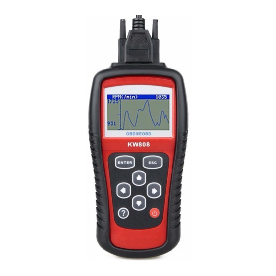
- Page 34 If the “G” icon appears when a PID is highlighted, it indicates graphic information is available. Press ENTER to view graph. RPM (/min) 1725 6) Press ESC button to return to previous menu. Viewing Custom Data Set 7) To view customized PID data, use UP/DOWN scroll button to select Custom Data Set from View Data menu and press ENTER button.
- Page 35 9) Use RIGHT button to deselect/select data parameters, and use UP/DOWN scroll button to move up and down. Selected parameters are marked with solid squares. …………..Custom Data Set………… … ■DTC_CNT □FUELSYS1 ■FUELSYS2 ■LOAD_PCT(%) □ETC(℃) ► □SHRTFT1(%) The number “x” to the upper right corner of the screen indicates sequence of highlighted item;...
- Page 36 ………………….Live Data…………………. DTC_CNT FUELSYS2 ETC(℃) ► SHRTFT1 (%) Use ESC button to return to View Data menu and/or return to Live Data menu. Recording Data The Record Data function allows recording vehicle modules’ Parameter Identification (PID) data help diagnose intermittent vehicle problems. A recording includes 5 frames of live data before trigger event and several frames after trigger event.
- Page 37 ……………….Live Data……………………. View Data ► Record Data Playback Data Recording Complete Data Set To record complete set of live data, use UP/DOWN scroll button to select Complete Data Set from Record Data menu and press ENTER button. ………………..Record Data……… …….. ►...
- Page 38 ……………Manual Trigger………… …... Ready to record! Press [ENTER] to start recording… Press [ESC] to exit Or following screen shows when DTC Trigger is selected: ………………….DTC Trigger…………….. Waiting for DTC to trigger recording… Press [ESC] to exit Use UP/DOWN scroll button to select a memory location and press ENTER button.
- Page 39 Select Memory A previous recording exists! Do you want to overwrite it? If you wish to proceed with overwriting the old recording, press ENTER button; if you do not wish to overwrite it, use LEFT/RIGHT button to select NO or press ESC button to pick another memory location.
- Page 40 Drive till a DTC is detected when DTC Trigger is selected. If no DTCs are detected, press ESC to exit recording. Recording… 5/60 DTC_CNT FUELSYS1 FUELSYS2 LOAD_PCT(%) ETC(℃) ► SHRTFT1(%) The number “x/x...” to the upper right corner of the screen indicates the maximum frames that can be recorded and the number of recorded frames.
- Page 41 ………………….Record Data……… ……. ► Complete Data Set Custom Data Set Unit of Measure Recording Custom Data Set To record customized data, use UP/DOWN scroll button to select Custom Data Set from Record Data menu and press ENTER button. ………………Record Data…………… … Complete Data Set ►...
- Page 42 …………Custom Data Set……… …….. ■DTC_CNT □FUELSYS1 ■FUELSYS2 ■LOAD_PCT(%) □ETC(℃) ► □SHRTFT1(%) You are allowed to pick up a maximum of 18 PIDs. If the selected PIDs exceed 18, a “The selected data list is full!” message displays on the screen. If you wish to deselect all marked items, press LEFT button.
- Page 43 ……………Pick Trigger Mode…… ……. ► Manual Trigger DTC Trigger If data from previously tested vehicle is not erased, data from current test will be stored in temporary cache. Following screen shows when Manual Trigger is selected: ……………Manual Trigger………… …... Ready to record! Press [ENTER] to start recording…...
- Page 44 …………. Select Memory……… ………. ► Location #1 Location #2 Location #3 The asterisk (*) icon on the screen indicates that there is a previous recording in the memory location. If you select a location marked with an asterisk (*) icon, a message prompting to overwrite old recording is displayed.
- Page 45 If DTC Trigger is selected, following screen shows: ………… Trigger…… … … Waiting for DTC to trigger recording… Press [ESC] to exit 14) Wait for DTC to trigger recording or press ENTER to start recording. ………… Recording… 5/60…. DTC_CNT FUELSYS1 FUELSYS2 LOAD_PCT(%) ETC(℃)
- Page 46 LEFT/RIGHT button to select NO and press ENTER button to return to Record Data menu. ………………Record Data………………… ► Complete Data Set Custom Data Set Unit of Measure Playing Back Data The Playback Data function allows viewing of previously stored PID data. To playback recorded data, use UP/DOWN scroll button to select Playback Data from Live Data menu and press ENTER button.
- Page 47 Select Memory Location #1 Location #2 ► Location #3 If there is no recording in selected location, a message “Not Supported or Stored No Data” displays on the screen. For data stored in temporary cache, you do not have to select memory location.
-
Page 48: Viewing Freeze Frame Data
Playback 6/16 DTC_CNT FUELSYS1 FUELSYS2 ► LOAD_PCT(%) ETC(℃) SHRTFT1(%) 5.4 Viewing Freeze Frame Data To view freeze frame data, use UP/DOWN scroll button to select View Freeze Frame from Diagnostic Menu and press ENTER button..Diagnostic Menu..... 4/11 Read Codes Erase Codes Live Data... -
Page 49: Retrieving I/M Readiness Status
…………View Freeze Frame… ………. DTC_CNT 1630 ►FUELSYS1 FUELSYS2 LOAD_PCT (%) ECT(℃) SHRTFT1 (%) If there is no freeze frame data available, an advisory message “No freeze frame data stored!” shows on the display. If you want to view full name of a PID, use UP/DOWN scroll button to select the PID, and press HELP button. - Page 50 This Drive Cycle - indicates status of monitors since the beginning of the current drive cycle. An I/M Readiness Status result of “NO” does not necessarily indicate that the vehicle being tested will fail the state I/M inspection. For some states, one or more such monitors may be allowed to be “Not Ready”...
- Page 51 ……………I/M Readiness……… ► Since DTCs Cleared This Drive Cycle 4) Use UP/DOWN scroll button, as necessary, to view the status of the MIL light (“ON” or “OFF) and the following monitors: Misfire monitor -- Misfire monitor Fuel System Mon -- Fuel System Monitor Comp.
-
Page 52: O2 Monitor Test
…………..This Drive Cycle……… ……. MIL Status Misfire Monitor Fuel System Mon Comp. Component Catalyst Mon Htd Catalyst 6) Press ESC button to return to Diagnostic Menu. 5.6 O2 Monitor Test OBD2 regulations set by SAE require that relevant vehicles monitor and test the oxygen (O2) sensors to identify problems related to fuel efficiency and vehicle emissions. - Page 53 Wait a few seconds while the scan tool validates the PID MAP. ……………O2 Monitor Test……………. Reading PID… - Please Wait - Use UP/DOWN scroll button to select O2 sensor from O2 Monitor Test menu and press ENTER button.....O2 Monitor Test………...
-
Page 54: On-Board Monitor Test
… ……….O2 Bank1 Sensor2…………. Rich-Lean Threshd (V) MOD: MEAS: 0.580 MIN: 0.100 MAX: ----- Use UP/DOWN scroll button to view more screens of data if an or icon displays. Press ESC button to return to the previous menus. 5.7 On-Board Monitor Test The On-Board Monitor Test is useful after servicing or after erasing a vehicle’s control module memory. - Page 55 On-Board Mon. Test Reading PID… - Please Wait - From On-Board Mon. Test menu, use UP/DOWN scroll button to select a test to view and press ENTER button. On-Board Mon. Test ►Test $01 Data Test $05 Data Test $09 Data If the vehicle under test does not support the mode, an advisory message will be displayed on the screen.
- Page 56 On-Board Mon. Test ….. ►O2 Mon. B1S1 O2 Mon. B1S2 Catalyst Mon. B1 EGR Mon. Bank1 Use UP/DOWN scroll button to select the desired monitor from On-Board Mon. Test menu and press ENTER button. View test data on screen. Test $01 Data MOD : MEAS: MAX :...
-
Page 57: Component Test
5.8 Component Test The Component Test function allows initiating a leak test for the vehicle's EVAP system. The scan tool itself does not perform the leak test, but commands the vehicle's on-board computer to start the test. Different vehicle manufacturers might have different criteria and methods for stopping the test once it has been started. - Page 58 Component Test ►Evap Leak Test 4) If the test has been initiated by the vehicle, a confirmation message will be displayed on the screen. Working Command Sent! Press any key to con. Some vehicles do not allow scan tools to control vehicle systems or components.
-
Page 59: Viewing Vehicle Information
5.9 Viewing Vehicle Information The Vehicle Info. function enables retrieval of Vehicle Identification (VIN), Calibration Nos. (CINs), Calibration Verification Nos. (CVNs) and In-use Performance Tracking on 2000 and newer vehicles that support Mode 9. 1) Use UP/DOWN scroll button to select Vehicle Info. from the Diagnostic Menu and press ENTER button. - Page 60 Vehicle Info. Reading info… - Please Wait - If the vehicle does not support this mode, a message shows on the display warning that the mode is not supported. 4) From Vehicle Info. menu, use UP/DOWN scroll button to select an available item to view and press ENTER button.
-
Page 61: Modules Present
5.10 Modules Present The Modules Present function allows viewing of the module IDs and communication protocols for OBD2 modules in the vehicle. 1) Use UP/DOWN scroll button to select Modules Present from Diagnostic Menu and press ENTER button. Diagnostic Menu 10/11 On-Board Mon. - Page 62 Place included CD into CD-Drive, or download applications from our website: www.auteltech.com or our distributors’ websites. Follow onscreen instructions on your computer to install applications. Launch Maxi-Link Tool Kit, and start printing application by selecting Scan Tools → → MS509 Print.
- Page 63 Print Data On-Board Mon. Test Vehicle Info. Print All Data ► Press ENTER button to upload data to the computer. http://www.obd2be.com/...
-
Page 64: Appendix
7. Appendix 7.1 Appendix 1-- PID List PID Abbreviation Full Name DTC_CNT DTC Stored Number DTCFRZF FUELSYS1 Fuel System 1 Status FUELSYS2 Fuel System 2 Status LOAD_PCT (%) Calculated Load Value ETC(°F) Engine Coolant Temperature ETC(°C) Engine Coolant Temperature SHRTFT1 (%) Short Term Fuel Trim-Bank1 SHRTFT3 (%) Short Term Fuel Trim-Bank3... - Page 65 PID Abbreviation Full Name AIR_STAT Commanded Secondary Air Status O2SLOC Location of O2 Sensors O2B1S1(V) O2 Sensor Output Voltage(B1S1) SHRTFTB1S1 (%) Short Term Fuel Trim(B1S1) O2B1S2(V) O2 Sensor Output Voltage(B1S2) SHRTFTB1S2 (%) Short Term Fuel Trim(B1S2) O2B1S3(V) O2 Sensor Output Voltage(B1S3) SHRTFTB1S3 (%) Short Term Fuel Trim(B1S3) O2B1S4(V)
- Page 66 PID Abbreviation Full Name SHRTFTB4S1 (%) Short Term Fuel Trim(B4S1) O2B4S2(V) O2 Sensor Output Voltage(B4S2) SHRTFTB4S2 (%) Short Term Fuel Trim(B4S2) OBDSUP OBD Require To Which Vehicle Designed O2SLOC Location of O2 Sensors RUNTM(sec) Time Since Engine Start MIL_DIST(km) Distance Travelled While MIL Activated MIL_DIST(mile) Distance Travelled While MIL Activated FRP(kPa)
- Page 67 PID Abbreviation Full Name O2B1S2(V) O2 Sensor Voltage(wide range O2S)(B1S2) EQ_RATB2S1 Equivalence Ratio(wide range O2S)(B2S1) O2B2S1(V) O2 Sensor Voltage(wide range O2S)(B2S1) EQ_RATB2S2 Equivalence Ratio(wide range O2S)(B2S2) O2B2S2(V) O2 Sensor Voltage(wide range O2S)(B2S2) EQ_RATB3S1 Equivalence Ratio(wide range O2S)(B3S1) O2B3S1(V) O2 Sensor Voltage(wide range O2S)(B3S1) EQ_RATB3S2 Equivalence Ratio(wide range O2S)(B3S2) O2B3S2(V)
- Page 68 PID Abbreviation Full Name O2S14(mA) O2 Sensor Current(wide range O2S)(B1S4) EQ_RAT21 Equivalence Ratio(wide range O2S)(B2S1) O2S21(mA) O2 Sensor Current(wide range O2S)(B2S1) EQ_RAT22 Equivalence Ratio(wide range O2S)(B2S2) O2S22(mA) O2 Sensor Current(wide range O2S)(B2S2) EQ_RAT23 Equivalence Ratio(wide range O2S)(B2S3) O2S23(mA) O2 Sensor Current(wide range O2S)(B2S3) EQ_RAT24 Equivalence Ratio(wide range O2S)(B2S4) O2S24(mA)
- Page 69 PID Abbreviation Full Name CATEMP22(°F) Catalyst Temperature Bank2Sensor2 CATEMP22(°C) Catalyst Temperature Bank2Sensor2 VPWR(V) Control Module Voltage LOAD_ABS (%) Absolute Load Value EQ_RAT Commanded Equivalence Ratio TP_R (%) Relative Throttle Position AAT(°F) Ambient Air Temperature AAT(°C) Ambient Air Temperature TP_B (%) Absolute Throttle Position B TP_C (%) Absolute Throttle Position C...
-
Page 70: Appendix 2 -- In-Use Performance Tracking Data List
7.2 Appendix 2 -- In-use Performance Tracking Data List Abbreviation Full Name Definitions OBDCOND OBD Monitoring Monitoring Conditions Conditions Encountered Counts displays number of times that the vehicle has Encountered been operated in the specified OBD Counts monitoring conditions (general denominator). - Page 71 O2SCOMP1 O2 Sensor Monitor O2 Sensor Monitor Completion Completion Counts Counts Bank 1 displays number of time that all conditions necessary to Bank 1 detect an oxygen sensor bank 1 malfunction have been encountered (numerator). O2SCOND1 O2 Sensor Monitor Sensor Monitor Conditions Conditions...
- Page 72 AIRCOMP AIR Monitor AIR Monitor Completion Condition Completion Counts (Secondary Air) displays number of time that all conditions Condition Counts necessary to detect an AIR system (Secondary Air) malfunction have been encountered (numerator). AIRCOND AIR Monitor Monitor Conditions Conditions Encountered Counts (Secondary Air) displays number of times that...
-
Page 73: Warranty And Service
8. Warranty and Service 8.1 Limited One Year Warranty Autel warrants to its customers that this product will be free from all defects in materials and workmanship for a period of one (1) year from the date of the original purchase, subject to the following terms and...
Need help?
Do you have a question about the Maxiscan MS509 and is the answer not in the manual?
Questions and answers