Table of Contents
Advertisement
Quick Links
Advertisement
Table of Contents

Subscribe to Our Youtube Channel
Related Manuals for mac.pan MK500 T

Summary of Contents for mac.pan MK500 T
- Page 1 Bechtop sheeter MK500 T...
-
Page 3: General Information
General information General information Documentation supplied • Instruction manual (this booklet). • Enclosure 1 EC Declaration of conformity • Enclosure 2 Spare parts catalogue • Enclosure 3 Wiring diagrams This manual Details about manual Instruction Manual: • Edition: 1.0 • Year and month of printing: November 2009 Addressees •... -
Page 4: Printing Conventions
General information Information property rights This manual contains copyright information. All rights are reserved. No part of this manual can be reproduced or photocopied without the prior written permission of the Manufacturer. Permission to use this documentation has only be given to the customer to whom the manual has been supplied as part of the machine's equipment and only for the purpose of installation, operation and maintenance of the machine to which the manual refers. - Page 5 General information ATTENTION BEWARE INDICATIONS DESCRIBE THE PROCEDURES THE PARTIAL OR TOTAL NON-OBSERVANCE OF WHICH CAN CAUSE DAMAGE TO THE MACHINE OR TO DEVICES CONNECTED TO IT. Danger Danger indications describe the procedures the partial or total non-observance of which can injure or harm the operator's health. Symbols used for the professional figures to whom this manual is directed Employer This symbol identifies the contents of the manual or the procedures intended for the...
-
Page 6: Manufacturer Identification Data
General information Mechanical technician This symbol identifies the contents of the manual or the procedures intended exclusively for the MECHANICAL ENGINEER. The mechanical engineer shall be a skilled person who has read and understood all the information contained in this manual and who has been authorised by the Manufacturer (after having received training by the latter) to act on the mechanical parts of the machine and to make adjustments and to carry out mechanical maintenance. -
Page 7: Machine Identification Data
General information Machine identification data Fig. 1.1 Name plate Type: Bechtop sheeter Model: MK500T Serial number: ______________ Year of manufacture: _________ EC declaration of conformity Enclosure 1 EC Declaration of conformity Guarantee General conditions This machine is guaranteed for 24 months after the date of actual delivery. This guarantee is, however, subject to the claim being made by means of registered letter, within 8 days after discovery of any faults or defects providing that prior confirmation and acknowledgement is obtained from the manufacturer. -
Page 8: After Sales Service
General information The guarantee will expire in the following cases • Improper machine use (see Chapter Intended use on page 55). • Use of equipment different from the equipment specified. • Use of the machine in conditions different from those specified in 5 Installation •... -
Page 9: Use Of The Manual
General information Request for assistance Technical Service Department Note When requesting assistance always quote the type, model and serial number of the machine. 1.10 Use of the manual Leggere attentamente: 1 General information 2 Safety information 3 Machine features Installation Consult the relevant chapter before attempting installation, operation, maintenance or dismantlement. -
Page 10: Machine Structure
General information Conditions of intended use The machine is designed and built to work in closed environments, sheltered from the weather, and intended for use in the food industry and in food preparation premises. Power supply The machine is driven by electric energy, which is converted into mechanical energy for the intended operations. -
Page 11: Safety Information
Safety information Safety information Safety criteria This machine has been designed and built using criteria and devices that meet the essential safety requirements laid out in: • Machine Directive 2006/62/EC • Low Voltage Directive 2006/95/EC • Electromagnetic Compatibility Directive 2004/108/EC •... -
Page 12: Qualifications Of Personnel
Safety information Qualifications of personnel Stage in the technical life of Qualification of operator in charge the machine Transport Qualified carrier informed of: 2 Safety information, 5 Installation. Installation Qualified electrician and qualified mechanic informed of: 2 Safety information, 3 Machine features, 4 Operator interface 5 Installation. - Page 13 Safety information Hazardous areas and residual risks Definition A hazardous area is any area inside or in the vicinity of the sheeter which would constitute a risk for the health and safety of an exposed operator. This manual indicates all the procedures during which residual risks for the operator are present. The residual risks can be eliminated by carefully following the procedures indicated in this manual and by using the recommended personal safety equipment.
- Page 14 Safety information ATTENTION USE OF THE HAIR-RESTRAINING CAP IS MANDATORY FOR THE MACHINE OPERATOR AND HYGIENE REGULATIONS REGARDING THE FOOD INDUSTRY MUST BE STRICTLY OBSERVED. RESIDUAL RISKS OPERATION STAGE RISKS Required P.P.E.: TRANSPORT AND INSTALLATION • Impact • Drawing in and crushing •...
- Page 15 Safety information OPERATION STAGE RISKS Required P.P.E.: MAINTENANCE • Impact • Drawing in and crushing • Shearing • Cutting • Entanglement • Loss of stability • Areas which machine • Contact with dust maintenance is carried out containing flour and processing ingredients •...
- Page 16 Safety information Fig. 2.1 Danger zones of the bread and pastry dough sheeter DESCRIPTION removable accessory for flour distribution (danger : drawing in and crushing). gap between the rollers from the side that rotates inwards (danger: drawing in and crushing); Safeguards Definition Safeguards are any safety measures which involve the application of specific technical...
- Page 17 Safety information Fig. 2.2 Fixed and moveable guards Interlock devices MK500B Dough Sheeter is fitted with interlock devices situated inside the guards that protect the electrical components. shows the two Fig. Interlock devices page microswitches that shut down the machine immediately when the grills are lifted to prevent accidental contact with the sheeting area.
- Page 18 Safety information Noise Data concerning airborne noise produced by the machine, measured in accordance with the indications set out in the Machinery Directive (2006/42/CE and its amending directives). The noise is not considered a great hazard for this type of machine, however noise tests were carried out in accordance with the procedure described in Annex B of the harmonised standard UNI EN 1674.
-
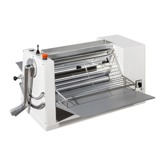
Page 19: Machine Features
Machine features Machine features Technical specifications Fig. 3.1 MK500T Dough Sheeter Dimensions and weight of the machine Machine Weight Model dimensions when open MK500T 99x90x50 cm Other technical characteristics Length Diameter Opening Table Model cylinders cylinders cylinders measurements MK500T 496 mm 60 mm 0-40 mm 500 mm... - Page 20 Machine features Tolerances of the electrical power supply Voltage Running voltage: ± of rated voltage. Frequency ±1% of rated frequency in continuous running. ±2% of rated frequency for a short working period. Harmonics The harmonic distortion, for the sum of harmonics from the second to the fifth, should not exceed 10% of the total voltage with effective value between live conductors.
-
Page 21: Operator Interface
Operator interface Operator interface Control panel Fig. 4.1 Control panel Symb. Description Controlled functions Main switch If on I it powers up the machine, if on O it cuts off the power to the machine, completely isolating it from the electrical energy sources. START button Press to activate the machine. -
Page 22: Other Controls
Operator interface Other controls Symb. Description Controlled functions Main switch If on I it powers up the machine, if on O it cuts off the power to the machine, completely isolating it from the electrical energy sources. Sheet thickness Rotate to increase or reduce the distance between the sheeting selection lever rollers according to the desired sheet thickness. -
Page 23: Preliminary Installation Procedures
Installation Installation Preliminary installation procedures Transporting and moving the machine Fork lift truck driver The transportation and moving operations must be carried out by a trained, skilled fork lift truck driver. OPERATION STAGE RISKS Required P.P.E. TRANSPORT AND INSTALLATION • Impact •... - Page 24 Installation Symbols on the machine packing The following symbols are shown on the machine packing: • Handle with care. • Centre of gravity. • Hooking point. • Store in a dry place. • This side up. • CE marking. Fig. 5.1 Pictograms Handle with care Store in a dry place Centre of gravity...
- Page 25 Installation Lifting ATTENTION • IT IS FORBIDDEN TO CLIMB ONTO THE MACHINE AND/OR ITS PACKING • ACCESS TO THE LIFTING AND HANDLING AREA IS DENIED TO ALL PERSONNEL EXCEPT THOSE DIRECTLY INVOLVED IN THE OPERATIONS. • BEFORE STARTING THE OPERATIONS THE WHOLE OF THE MACHINE HANDLING AREA, INCLUDING THE PARKING AREA FOR THE MEANS OF TRANSPORT AND THE MACHINE INSTALLATION AREA SHOULD BE IDENTIFIED AND INSPECTED.
- Page 26 Installation Fig. 5.2 Lifting the package with the lift truck Note Follow standard precautions to avoid collisions and tipping over. ATTENTION USE ONLY LIFTING EQUIPMENT TO LIFT THE MACHINE AND IT IS STRICTLY PROHIBITED TO STAND UNDER A SUSPENDED LOAD. THE ACCELERATION AND DECELERATION FORCES DURING TRANSPORTATION MUST BE WITHIN THE RANGE OF PERMISSIBLE TOLERANCES.
- Page 27 Installation Unpacking ATTENTION • BEFORE UNPACKING THE MACHINE, CHECK THE CRATE FOR SIGNS OF BREAKAGES OR SIGNIFICANT DENTING. IF THE CRATE IS DAMAGED INFORM THE CARRIER WHO DELIVERED IT. • FOR DISPOSAL OR RECYCLING OF PACKAGING MATERIALS THE CUSTOMER MUST COMPLY WITH THE NATIONAL REGULATIONS IN FORCE ATTENTION IF THE MACHINE HAS BEEN DAMAGED DURING TRANSPORT, INFORM THE MANUFACTURER IMMEDIATELY.
- Page 28 Installation ATTENTION RESPECT THE MINIMUM POSITIONING MEASUREMENTS SHOWN IN FIG. 5.4 ON PAGE 75 TO GUARANTEE EASY AND SAFE ACCESS BOTH FOR THE OPERATOR AND FOR MAINTENANCE ENGINEERS. Fig. 5.3 Machine lifting Check if the machine has been damaged during transport Check the condition of the machine taking a close look at the outside.
- Page 29 Installation Fig. 5.4 Positioning Mounting the infeed and outfeed tables (teflon- coated) Mechanical technician The assembly operations of the machine and its parts should only be carried out by trained, qualified and authorised personnel after having read and understood the information given in this manual.
- Page 30 Installation Mounting/removing the scraper The scraper must be positioned on the machine, in the one possible direction dictated by the 3 fixing holes. To remove it from the machine proceed as follows: • Remove the flour tray (Fig. 1.2 on page 56) by undoing the two screws on the side; •...
- Page 31 Installation Storage The indications contained in this section must be observed during the temporary storage of the machine that could occur in the following situations: • Machine not installed immediately after delivery . • Machine uninstalled and placed in storage in anticipation of a relocation. ATTENTION IT IS STRICTLY FORBIDDEN TO CLIMB ONTO THE BOX PALLETS AND/OR TO STOW THEM ONE ON TOP OF THE OTHER.
- Page 32 Note When reading this chapter refer to the figure and description of the control panel given in the 4 Operator interface Chapter. Hazardous areas and residual risks during use OPERATION STAGE RISKS Required P.P.E. • Impact • Drawing in and crushing •...
-
Page 33: Work Station
Preliminary controls before putting the machine into service Before putting the machine into service the operator must carry out the following controls: • Make sure that the teflon-coated tables are mounted correctly (see Fig. 5.5 on page 75); • Make sure that the protection grills are lowered; •... -
Page 34: Work Cycle
Adjustment warnings • All adjustment, checking or cleaning operations must be carried out with the machine at a standstill and the electric control box off. The main on-off switch must be set to position O and padlocked ATTENTION ANY OPERATION CARRIED OUT WHILE THE WIRING SYSTEM IS LIVE CAN CAUSE SERIOUS INJURIES. -
Page 35: Switching Off The Machine
Routine stopping of machine Stopping procedure: • To stop the machine under normal conditions (e.g. end of a work cycle) press the STOP button • To restart the machine after a normal stop, press the button 6.10 Switching off the machine To switch the machine off: •... -
Page 36: Maintenance
Maintenance Maintenance Maintenance guidelines Operator The control and maintenance operations must be carried out by qualified operators who are familiar with the instructions set out in this manual. Mechanical technician The control and maintenance operations must be carried out by qualified operators who are familiar with the instructions set out in this manual. -
Page 37: Routine Maintenance
Maintenance Hazardous areas and residual risks during maintenance OPERATION STAGE RISKS Required P.P.E.: MAINTENANCE • Impact • Drawing in and crushing • Shearing • Cutting • Entanglement • Loss of stability • Areas which machine • Contact with dust maintenance is carried out containing flour and processing ingredients •... - Page 38 Maintenance Regular cleaning of your machine will ensure its good working order. We recommend the following: • Clean the machine at the end of each shift. • The cleaning of the machine keeps the most delicate parts in good working order and helps to spot any loosening of parts and any abnormal wear and tear.
-
Page 39: Scheduled Servicing
Maintenance Spray zone The spray zone is defined as follows: • the internal and lateral part of the base; • the external part of the solid guards. Non-foodstuff zone The remaining parts of the machine that are not in contact with the foodstuff. Cleaning method Parts to be cleaned Method and tools... - Page 40 Maintenance Every day: • Check that the protection grills function correctly. • Visually check the wear and tear condition of the electric power cable and plug. • Clean the sheeter • Clean the scrapers. After the first 100 hours of work and/or once a year: •...
-
Page 41: Disconnecting The Machine
Scrapping Scrapping Qualifications of operator Mechanical technician Qualified mechanical engineer who is familiar with the contents of the sections on Safety information 8 Scrapping Hazardous areas and residual risks during deactivation OPERATION STAGE RISKS Required P.P.E.: DISCONNECTION • Impact • Drawing in and crushing •... - Page 42 Scrapping Procedures and information for deactivating the machine Pursuant to Art. 13 of Legislative Decree no. 151 of 25 July 2005, Implementation of Directives 2002/95/EC, 2002/96/EC and 2003/108/EC, concerning the restriction of the use of certain hazardous substances in electrical and electronic equipment, and the disposal of waste electrical and electronic equipment.
- Page 43 Enclosures Enclosures Enclosure 1 EC Declaration of conformity Enclosure 2 Spare parts catalogue Enclosure 3 Wiring diagrams bechtop sheeter SFB500SM Bechtop sheeter SFB500SM_INGLESE.fm...
- Page 44 Enclosures Enclosure 1 EC declaration of conformity (in compliance with Annex II.A of the Machinery Directive 98/37/EC and its amending directives) The manufacturer DECLARES that the following machine model: Name: Benchtop sheeter Model: MK500T Serial number: ___________ Year of manufacture: ______ COMPLIES WITH THE REQUIREMENTS OF THE MACHINERY DIRECTIVE AND WITH THE NATIONAL PROVISIONS ADOPTED PURSUANT TO THIS DIRECTIVE.
-
Page 45: Spare Parts
Enclosures SPARE PARTS Enclosure 2 Spare parts catalogue Dough Sheeter MK500T Model NO. REF. PROTECTIVE GRILL ROD CODE PROTECTIVE GRILL ROD PROTECTIVE GRILL TOOTHED SECTOR LEVER END-OF-STROKE SECTOR LEVER STROKE STOP HANDLE LEVER FOR HANDLE FLOUR TRAY bechtop sheeter SFB500SM Bechtop sheeter SFB500SM_INGLESE.fm... - Page 46 Enclosures SPARE PARTS Model Dough Sheeter MK500T NO. REF. DESCRIPTION CODE MICROSWITCH FOR GUARD CLOSURE RIGHT CONNECTING ROD FLANGE BUSHING FEED TABLE bechtop sheeter SFB500SM_INGLESE.fm SFB500SM Bechtop sheeter...
- Page 47 Enclosures SPARE PARTS Dough Sheeter MK500T Model 15 16 17 18 NO. REF. DESCRIPTION CODE CONNECTING ROD SHIFT DEVICE LIFTING SHAFT CHAIN STRETCHER CROWN CIRCLIP BEARING 6005 2RS TIE ROD FOR CHAIN LEFT CONNECTING ROD ECCENTRIC BUSHING FLANGE PINION Z=16 3/8" CHAIN 3/8 DOUBLE MAIN SWITCH SPRING...
- Page 48 SPARE PARTS Enclosures Model Dough Sheeter MK500T NO. REF. DESCRIPTION CODE FUSES ELECTRIC BOARD bechtop sheeter SFB500SM_INGLESE.fm SFB500SM Bechtop sheeter...
-
Page 49: Wiring Diagram
WIRING DIAGRAM bechtop sheeter... - Page 50 WIRING DIAGRAM bechtop sheeter...
- Page 52 www.macpan.com...
Need help?
Do you have a question about the MK500 T and is the answer not in the manual?
Questions and answers