Baroness LM331 Owner's Operating Manual
3-unit surround & trim mower
Hide thumbs
Also See for LM331:
- Service manual (165 pages) ,
- Owner's operating manual (103 pages) ,
- Owner's operating manual (88 pages)

Related Manuals for Baroness LM331


Summary of Contents for Baroness LM331
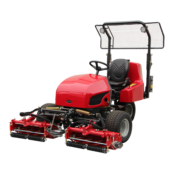
- Page 1 3-Unit Surround & Trim Mower Owner's Operating Manual Serial No. LM331:20001- "Required reading" Read this manual before using the machine. Original Instructions Ver.3.1...
-
Page 2: California Proposition
LM331 Regulations California Proposition 65 California Spark Arrester (For California, USA) (For California, USA) Warning WARNING: Operation of this equipment may create Operating, servicing and maintaining sparks that can start fires around dry a passenger vehicle or off-road vegetation. vehicle can expose you to chemicals A spark arrester may be required. - Page 3 LM331 Greeting Thank you for purchasing the Baroness product. Keeping the Owner's Operating Manual This manual describes the proper handling, adjustment, and inspection of your product. Keep this Manual in the box on the left side of We hope you will use the product safely, and take the ROPS.
-
Page 4: Warning Symbols
The operator is responsible for operating the product properly and safely. Maintenance service for this machine should be performed by a mechanic with expertise. If you have any questions concerning maintenance or genuine parts, please contact a Baroness dealer or Kyoeisha. -
Page 5: Precautionary Statement
When replacing parts, be sure to use genuine Baroness parts or parts designated by Kyoeisha. Note that the Baroness product warranty may not apply to defects caused by the use of parts from other companies. Prior to use, carefully read the following manuals to thoroughly understand the contents for safe and correct operation. - Page 6 LM331 Introduction...
-
Page 7: Table Of Contents
LM331 Contents Safety .............. Page 1-1 Precautions for Maintenance ......Page 6-2 Jacking Up The Machine ....... Page 6-2 Safe Operating Practices .......Page 1-2 Hoisting The Machine ........Page 6-3 Disposal ............Page 2-1 Inspection and Cleaning ........ Page 6-4 Supplying Fluids .......... - Page 8 LM331 Contents...
-
Page 9: Safety
LM331 Safety Safe Operating Practices ...... Page 1-2 Training ..........Page 1-2 Preparation ..........Page 1-2 Operation ..........Page 1-3 Maintenance .......... Page 1-4 Storage ..........Page 1-5 Page 1-1... -
Page 10: Safe Operating Practices
LM331 Safety Failure to adequately follow these safety Never allow children or people unfamiliar precautions may cause an accident resulting in with these instructions to use or service the injury or death. machine. Local regulations may restrict the age of the Danger operator. -
Page 11: Operation
LM331 Safety Add fuel before starting the engine. Never operate while people, especially Never remove the cap of the fuel tank or children, or pets are nearby. add fuel while the engine is running or Only operate in good light, keeping away when the engine is hot. -
Page 12: Maintenance
LM331 Safety Do the following before leaving the Implement the following work before operator's position. adjusting, cleaning or repairing. Stop on level ground. Stop the machine on level ground. Disengage the all drives. Disengage drive to the cutting unit(s). Set the parking brake. -
Page 13: Storage
LM331 Safety When checking the hydraulic circuit for Swallowing engine coolant can cause injury pinhole leaks or oil leakage from nozzles, do or death; keep out of reach from children and not use your hands. pets. Use items such as paper or corrugated cardboard to find leakage points. - Page 14 LM331 Safety Page 1-6 Safe Operating Practices...
-
Page 15: Disposal
LM331 Disposal Recycle and Waste Disposal ....Page 2-2 About Recycle ........Page 2-2 About Waste Disposal ......Page 2-2 Page 2-1... -
Page 16: Recycle And Waste Disposal
LM331 Disposal Recycle and Waste Disposal About Recycle Recycling battery etc. is recommended for environmental conservation and economical use of resources. It may be required by local laws. About Waste Disposal Make sure that waste generated when servicing or repairing the machine is disposed of in accordance with local regulations. -
Page 17: Product Overview
LM331 Product Overview Specifications ........Page 3-2 Specifications .........Page 3-2 Mower Units ...........Page 3-3 Sound Pressure Level ......Page 3-3 Sound Power Level ....... Page 3-3 Vibration Level ........Page 3-3 Carbon Dioxide (CO2) Emissions ..Page 3-3 Names of Each Section ......Page 3-4 Regulation Decals ........Page 3-6... -
Page 18: Specifications
LM331 Product Overview Specifications Specifications Model LM331 Name 3-Unit Surround & Trim Mower Mower unit type 26 in Total length 254 cm 100.00 in Total width 212 cm 83.46 in Dimensions Steering wheel 126 cm 49.61 in Total height ROPS 196 cm 77.17 in... -
Page 19: Mower Units
The factory default maximum engine rpm is 2,800 rpm. Mower Units Vibration Level Baroness mower unit that can fit this machine Hand-Arm Vibration is the model marked with a circle in the This machine was confirmed not to exceed a "Attachable unit"... -
Page 20: Names Of Each Section
LM331 Product Overview Overall View B Names of Each Section Overall View A 4,5,6,7 F8D02D0D Names of Each Section_002 0E3E4073 Fuel tank Names of Each Section_001 Fuel filter Hood Engine Rear cover Engine oil filter Center cover Water separator Radiator... - Page 21 LM331 Product Overview Overall View C Operation panel B0187017 Names of Each Section_004 Key switch Light switch Throttle lever Water temperature gauge Fuel gauge Pilot lamp FC0AE047 Names of Each Section_003 Seat Steering wheel Tilt lever Traveling pedal Brake pedal...
-
Page 22: Regulation Decals
LM331 Product Overview Battery Regulation Decals Positions of Regulation Decals Main vehicle U P P E R L E V E L L O W E R L E V E L A,B,C,D F10F3DC0 Positions of Regulation Decals_002 Battery capacity decal... - Page 23 LM331 Product Overview CE Mark Year of Manufacture Decal (For EU) (For EU) CE mark indicates that the machine sold in The year of manufacture decal indicates the the EU nations complies with the EU year when this machine was manufactured.
- Page 24 LM331 Product Overview Indicating Diesel Fuel Decal Spark Arrester Warning Decal (for USA) (For the State of California, USA) It indicates the fuel to be used. Spark arrester warning decal describes the Use low sulfur or ultra-low sulfur diesel fuel warning messages as required by California (sulfur-free diesel fuel).
- Page 25 LM331 Product Overview EU Battery Regulation Decal Recycle Decal (For EU) Recycle Decal illustrates Recycle Mark in The EU battery regulation decal indicates accordance with local regulation. compliance with the EU battery regulation. (For EU) The following information about the battery manufacturing company is written in the decal.
-
Page 26: Safety Signs And Instruction Signs
6iul4h-151 Positions of Safety Decals and Instruction Decals_002 Part numbers for decals that need to be replaced are listed in the parts catalog. Order them from a Baroness dealer or Kyoeisha. Positions of Safety Decals and Instruction Decals 6iul4h-121... - Page 27 LM331 Product Overview Left panel decal Diesel fuel filler decal Hydraulic oil decal Fire prohibited decal Caution for high temperatures decal Caution to getting pinched decal Caution to getting entangled decal Caution for spouting coolant decal Caution to noise decal...
-
Page 28: Description Of Safety Decals And Instruction Decals
LM331 Product Overview Description of Safety Decals and Instruction Decals Warning Rollover - Do not switch between 2WD and Left Panel Decal 3WD while traveling on downward slopes. LM331--0928Z0 Do not set the reel rotation switch to the Decal, left panel "Rotation"... - Page 29 LM331 Product Overview Diesel Fuel Icon Fire Prohibited Decal K4209001000 K4205001940 Diesel fuel icon Decal, fire prohibited Use diesel fuel. Warning Keep away from fire. xmitt2-001 Diesel Fuel Icon_001 Hydraulic Oil Icon r653fo-001 K4209000980 Fire Prohibited Decal_001 Hydraulic oil icon Caution for High Temperatures Decal Read the Owner's Operating Manual.
- Page 30 LM331 Product Overview Caution to Getting Pinched Decal Caution for Spouting Coolant Decal K4205001930 K4205001970 Decal, caution to getting pinched Decal, caution for spouting coolant Caution Caution May pinch - There is a risk of being pinched. Caution for spouting coolant - Do not open while hot.
- Page 31 LM331 Product Overview Molybdenum Grease Decal K4209002020 DECAL, GREASE Add Moly speed grease No.2. 2D9ACD8B Molybdenum Grease Decal_001 Safety Signs and Instruction Signs Page 3-15...
-
Page 32: Operation Decals
LM331 Product Overview Operation Decals Positions of Operation Decals 6n6oux-198 Positions of Operation Decals_005 6n6oux-137 Positions of Operation Decals_001 6n6oux-199 Positions of Operation Decals_006 6n6oux-195 Positions of Operation Decals_002 6n6oux-200 Positions of Operation Decals_007 6n6oux-196a Positions of Operation Decals_003 DA53BF48... - Page 33 LM331 Product Overview Key switch decal Engine rotation decal Light switch decal Mower unit up/down decal Reel rotation decal 2WD - 3WD selector lever decal Tilt steering decal Parking brake decal BRAKE decal FORWARD decal BACKWARD decal Lapping switch decal...
-
Page 34: Description Of Operation Decals
LM331 Product Overview Description of Operation Decals Light Switch Decal Key Switch Mark Note: Depending on the specifications, this function Key switch mark may not be available. This indicates the key switch positions. LM331--1105Z0 Light switch decal This indicates the light switch positions. - Page 35 LM331 Product Overview Reel Rotation Mark Tilt Steering Decal Reel rotation mark K4203001500 It illustrates Rotation/Stop of the reel cutter Tilt steering decal (cutting cylinder). This illustrates the tilt directions of the steering wheel and the locked/free positions. 6ntnq3-001 hj3943-002...
- Page 36 LM331 Product Overview BRAKE Decal Lapping switch decal K4203001450 LM331--0556Z0 Decal, BRAKE Lapping switch decal This indicates brake. This indicates the ON/OFF positions for back lapping. BRAKE 7elqr2-001 BRAKE Decal_001 v57o51-002 Lapping switch decal_001 FORWARD Decal ON (back lapping rotation)
- Page 37 LM331 Product Overview Reel Stop Decal K4203001310 Decal, reel stop This indicates stop of the reel cutter (cutting cylinder). if834g-002 Reel Stop Decal_001 Differential Lock Decal K4203001420 Decal, differential lock This indicates the positions for engaging or releasing the differential lock.
- Page 38 LM331 Product Overview Page 3-22 Operation Decals...
-
Page 39: Description Of Functions
LM331 Description of Functions Proximity Sensor ........Page 4-2 2WD/3WD Selector Lever ...... Page 4-2 Key Switch ..........Page 4-2 Light Switch ........... Page 4-3 Diff-Lock Switch ........Page 4-3 Throttle Lever .........Page 4-3 Mower Unit Up/Down Lever ....Page 4-4 Reel Rotation Switch ......Page 4-4 Reel Reverse Switch ......Page 4-5... -
Page 40: Proximity Sensor
LM331 Description of Functions Proximity Sensor There is a proximity sensor on #2 mower arm fulcrum. This sensor detects the raised or lowered positions of mower unit #2. The information is related to controlling rotation and stop of the reel cutter (cutting cylinder). -
Page 41: Light Switch
LM331 Description of Functions Light Switch Caution The lights provide auxiliary lighting. Do not travel or operate the machine at night or under poor visibility. Note: Depending on the specifications, this function may not be available. C53AACD8 The light switch is located in the meter panel. -
Page 42: Mower Unit Up/Down Lever
LM331 Description of Functions Mower Unit Up/Down Lever Reel Rotation Switch Caution Caution Before raising or lowering the mower units, be Set the reel rotation switch to the "Rotation" sure to sit on the seat. position immediately before starting cutting work or back lapping. -
Page 43: Reel Reverse Switch
LM331 Description of Functions Reel Reverse Switch Reel Rotation/Stop Switching Lever Important Caution Do not switch the reel reverse switch to the Before operating the reel rotation/stop "ON" or "OFF" position while the reel cutter switching lever, be sure to set the reel rotation (cutting cylinder) is rotating. -
Page 44: Brake Pedal
LM331 Description of Functions Traveling pedal Forward Backward Brake Pedal The brake pedal is located in the left foot area. To stop the machine, firmly depress the brake pedal. r6e5n8-004 Parking Brake Lever_001 Brake pedal Parking brake lever Battery Cutoff Switch... -
Page 45: Instruments In The Meter Panel
LM331 Description of Functions Fuel Gauge Instruments in the Meter Panel The fuel gauge is located in the meter panel. This instrument indicates the quantity of fuel inside the fuel tank. 6o7242-001 F U E L Instruments in the Meter Panel_001... -
Page 46: Safety Device
LM331 Description of Functions Hour Meter Thermo-start Lamp The thermo-start lamp is the middle pilot The hour meter indicates the accumulated lamp, located in the meter panel. operation time of the engine. When the ignition key is set to the "GLOW"... -
Page 47: Warning Mechanisms
LM331 Description of Functions In the event the operator leaves the seat with the parking brake applied and the engine running, the safety device will be activated and will stop the engine under any of the following conditions: The traveling pedal is not set to the neutral ・... - Page 48 LM331 Description of Functions Page 4-10 Warning Mechanisms...
-
Page 49: Handling Instructions
LM331 Handling Instructions Operations Before Service ....Page 5-2 Procedure to Open/Close Hood .... Page 5-2 Procedure to Remove/Install Rear Cover ............. Page 5-3 Procedure to Remove/Install Center Cover ............. Page 5-4 Inspection Before Use ......Page 5-4 Engine ............Page 5-4 Main Vehicle .......... Page 5-7 Adjustment before Work ..... -
Page 50: Operations Before Service
LM331 Handling Instructions Release the rubber catches on the left and Operations Before Service right sides. The following sections describe the preparatory works required before performing the services including inspection, adjustment, cleaning. maintenance and repair. Procedure to Open/Close Hood Caution Do not open the hood in strong winds. -
Page 51: Procedure To Remove/Install Rear Cover
LM331 Handling Instructions If the ROPS or the ball proof net is Procedure to Remove/Install Rear Cover installed, follow the steps below to fold back the ROPS. Caution Remove the clip pins on the left and Do not remove the rear cover in strong winds. -
Page 52: Inspection Before Use
LM331 Handling Instructions If the ROPS or the ball proof net is Engine installed, follow the steps below to fold back the ROPS. Inspection of Engine Oil Remove the clip pins on the left and right sides of the ROPS, and then Important remove the lock pins. - Page 53 LM331 Handling Instructions Oil level gauge Upper limit Lower limit Inspection of Fuel Quantity With the machine on a level surface, observe the fuel gauge in the meter panel to check the fuel level. 2e4emp-006 Supply of Fuel_001 Tank cap Inspection of Fuel Filter Make sure that there is no fuel leakage.
- Page 54 LM331 Handling Instructions Fuel cock Caution Fuel filter Inspection should take place after the engine Air-bleeding plug has well cooled down. ON (Open) Make sure that the coolant level in the OFF (Close) reserve tank is between "FULL" and "LOW.”...
-
Page 55: Main Vehicle
LM331 Handling Instructions Inspection of Dust-proof Mesh Inspection of Tires Make sure that there is no damage to the Check the pneumatic pressure of the tires. dust-proof mesh. Make sure that there are no cracks, Make sure that the dust-proof mesh is not damage or abnormal wear. - Page 56 LM331 Handling Instructions Cleaning the exterior Warning Warning When refilling, do not fill purified water above Do not clean the battery with a dry cloth. the UPPER LEVEL line. Cleaning the battery with a dry cloth may Doing so may result in electrolyte leaks.
- Page 57 LM331 Handling Instructions Make sure that there is no abnormal sound Inspection of Covers when the pedal is depressed. Inspection of Liquid Leakage Warning If you have removed the cover during Important inspection, make sure that you replace it in the original position securely.
- Page 58 LM331 Handling Instructions Seat belt Inspection of Hour Meter (If the machine is equipped with ROPS and a seat belt) Check the hour meter is not damaged. Make sure that the seat belt is not damaged Check the hour meter operates correctly.
-
Page 59: Adjustment Before Work
LM331 Handling Instructions The steering wheel position can be adjusted up Adjustment before Work or down. Adjust the position to fit the operator. Adjustment of Seat Position Shift the tilt lever to the "FREE" position, move the steering wheel to the position that suits the... -
Page 60: Start/Stop Of Engine
LM331 Handling Instructions Shift the throttle lever from the "Low speed" Start/Stop of Engine position halfway to the "High speed" position. Procedure to Start Engine Important The thermo-start lamp turns off at the Caution specified time. However, the lamp turning off Before starting the engine, make sure that is not related to the glow plug generating heat. -
Page 61: Parking And Stopping
LM331 Handling Instructions After the thermo-start lamp turns off, Procedure to Stop Engine immediately set the ignition key to the "START" position. Set the traveling pedal to the neutral position. Important Apply the parking brake. Quickly returning the ignition key from the Set the reel rotation switch to the "Stop"... -
Page 62: Move
LM331 Handling Instructions Move Caution Cutting work must be performed at an Traveling Procedure appropriate speed for the site and location. When cutting over bumpy surfaces, keep the Caution engine rpm steady, and slow down the cutting Under any circumstances drive the machine at speed. -
Page 63: Transporting
LM331 Handling Instructions Procedure to Remove/Install Grass Grass catcher Catcher Grass catcher mounting bracket Mounting pin Caution Mower unit #3 Stop the engine before removing or installing the grass catcher. Set the reel rotation switch to the "Stop" position. Lower the mower units. - Page 64 LM331 Handling Instructions Open the hood. Cleaning of Dust-Proof Mesh (Refer to "Opening and Closing of Hood") Pull up the dust screen to remove it. Important An unclean dust-proof mesh may cause the engine to overheat. It may also cause malfunction of the hydraulic system.
-
Page 65: Main Vehicle
LM331 Handling Instructions Main Vehicle Cleaning of Oil Cooler Important An unclean oil cooler may cause malfunction of the hydraulic system. Important Do not use solid objects, such as a spatula or screwdriver, or high-pressure water to clean the radiator or oil cooler. - Page 66 LM331 Handling Instructions Page 5-18 Cleaning After Use...
-
Page 67: Maintenance
LM331 Maintenance Precautions for Maintenance ....Page 6-2 Jacking Up The Machine .......Page 6-2 About Jacking Up The Machine .....Page 6-2 Jack-up Points ........Page 6-2 Hoisting The Machine ......Page 6-3 About Hoisting The Machine ....Page 6-3 Lifting Points .......... Page 6-4 Inspection and Cleaning ....... -
Page 68: Precautions For Maintenance
First, learn well the operations you plan to perform. Important Use tools appropriate for each operation. Important Use Baroness genuine parts for replacement and accessories. Our product warranty may be void if you use non-genuine parts for replacement or accessories. -
Page 69: Hoisting The Machine
LM331 Maintenance Front right frame Hoisting The Machine About Hoisting The Machine Caution Hoist the machine on a level and stable place. Caution Remove the obstacles which may prevent safety operation before hoisting the machine. rwyt62-093 Jack-up Points_002 Front left frame Caution Use appropriate hoists, crane and ropes. -
Page 70: Inspection And Cleaning
LM331 Maintenance Failure prevention ・ Lifting Points Performance retention ・ Make efforts for early detection of the machine Important failure and prevention of the sudden occurrence Be sure to use adequately strong cables. of trouble. Perform maintenance and repair works immediately if any abnormality is found in the machine. - Page 71 LM331 Maintenance Soak the filter element in diesel fuel and Make sure that the water separator is not clean it. damaged or dirty. Clean inside of the filter cup with diesel fuel. Make sure that there is no water leakage.
- Page 72 LM331 Maintenance Close the fuel cock of water separator. Open the fuel cock of water separator. v1spa6-005 v1spa6-005 Draining of Water Separator_001 Draining of Water Separator_003 Fuel cock Fuel cock Air-bleeding plug Air-bleeding plug ON (Open) ON (Open) OFF (Close)
- Page 73 LM331 Maintenance Close the fuel cock of water separator. Open the fuel cock of water separator. v1spa6-005 v1spa6-005 Cleaning of Water Separator_001 Cleaning of Water Separator_003 Fuel cock Fuel cock Air-bleeding plug Air-bleeding plug ON (Open) ON (Open) OFF (Close)
-
Page 74: Main Vehicle
LM331 Maintenance Attach the air cleaner cap, and then fix it Main Vehicle securely with the clips. Inspection of Hydraulic Hoses and Pipes Warning When checking the hydraulic circuit for pinhole leaks or oil leakage from nozzles, do not use your hands. Use items such as paper or corrugated cardboard to find leakage points. -
Page 75: Supplying Fluids
LM331 Maintenance Inspection of Electrical Wiring Important Be sure to use engine oil that is classified as Important API Service Grade CF or higher, with an SAE Viscosity that is appropriate for the operating Electrical short circuit will cause fire, electrical environment (ambient temperature). - Page 76 LM331 Maintenance Install the reserve tank cap. Coolant Supply Caution Do not touch the radiator or coolant during engine operation or immediately after the engine has been turned off. Otherwise, you may get burned due to high temperatures. Caution ouuoov-023...
-
Page 77: Main Vehicle
LM331 Maintenance Main Vehicle Hydraulic Oil Supply Important Do not mix different types of oil. Important Use Shell Tellus S2M46 (or equivalent) as pfdche-014 hydraulic oil. Hydraulic Oil Supply_001 In the case of using an equivalent, consult Hydraulic tank Characteristics of Hydraulic Oil and use... -
Page 78: Greasing
LM331 Maintenance Lower the mower units and maintain that Tighten the vent plug securely. position on a level surface, and then check to see if the oil level is at the middle of the oil gauge. If the hydraulic oil level is low, supply oil U P P E R L E V E L again until it reaches the specified level. -
Page 79: Greasing Points
LM331 Maintenance Lift arm fulcrum Greasing Points Mower unit #1 Grease nipples are installed in the following There is one greasing point on the lift arm locations. fulcrum connected to the mower unit. Add grease every 50 hours of operation. - Page 80 LM331 Maintenance Brake pedal shaft fulcrum Tension lever 8bq62b-442 8bq62b-275 Greasing Points_005 Greasing Points_008 Brake lever shaft Neutral cam lever Add grease every 100 hours of operation or every year, whichever comes earlier. 8bq62b-276 Greasing Points_009 Traveling pedal shaft fulcrum...
- Page 81 LM331 Maintenance Front wheel brake lever Mower coupling There is one greasing point each on the left Mower unit #2 and #3 and right sides. There is one greasing point each on the Left side couplings connecting the mower units.
-
Page 82: Lubrication
LM331 Maintenance Piston pump shaft Lubrication Important About Lubrication Add grease to the piston pump shaft after It is necessary to lubricate moving parts so that loosening the air-bleeding bolt located under they will not become stuck or damaged. the pump shaft housing for 2 turns. -
Page 83: Adjustment
LM331 Maintenance Front mower cylinder spherical bearing Warning There are two locations. If a cover is removed due to inspection or adjustment, be sure to reinstall it in its original location. Important A slacking or damaged fan belt will cause overheating or lack of battery charge. -
Page 84: Main Vehicle
LM331 Maintenance Adjustment to suitable belt tension force by Main Vehicle using sonic type tension meters at a specified point Adjustment of Belt Tension Important Warning Perform correct measurement in accordance Be sure to stop the engine before adjusting with the operations manual of the equipment the belts. - Page 85 LM331 Maintenance The mower units do not tilt while operating ・ Lock nut on slopes, and incomplete mowing can be reduced. 30.0 - 35.0 mm (1.18 - 1.38 in) Released: ・ It is appropriate when turning while mowing After adjustment of belt tension, check the or it is easy to follow undulations.
-
Page 86: Replace
LM331 Maintenance Adjustment of Mower Stabilizer (LH Unit) Important When changing the engine oil, be sure to Note: drain it into a container and discard it in Depending on the specifications, this function accordance with local laws and regulations. may not be available. - Page 87 LM331 Maintenance Supply new engine oil through the oil filler Important port until the oil reaches a level in between the upper and lower limit lines on the oil Securely tighten the oil level gauge and oil level gauge. filler cap.
- Page 88 LM331 Maintenance Clean the inside of the filter cup with diesel Replacement of Fuel Filter Element fuel. If dust or dirt accumulates in the fuel filter, the Important fuel flow will become insufficient. During installation, prevent contamination with Replace the fuel filter at the appropriate times.
- Page 89 LM331 Maintenance Replace the air cleaner element by When mixing antifreeze and clean water, refer following the same steps as for cleaning the to "Relationship between concentration of air cleaner. long-life coolant (LLC) and freezing "Cleaning of Air Cleaner Element" (Page temperature"...
-
Page 90: Main Vehicle
LM331 Maintenance Remove the reserve tank. Important When you change the hydraulic oil, be sure to drain it into a bowl and discard it in accordance with local laws and regulations. Important If the hydraulic oil emulsifies or if it becomes even slightly less transparent, change the oil immediately. - Page 91 LM331 Maintenance Wind new sealing tape on the drain plug, Supply hydraulic oil through the oil filling and then install the drain plug into the port until the oil level reaches the middle hydraulic tank. of the oil gauge on the hydraulic tank.
- Page 92 LM331 Maintenance Replacement of Hydraulic Oil Filter Filter cartridge Filter case Caution Body Be careful with hot oil, which could cause Lightly coat the O-ring of the new filter burns if it contacts your skin. cartridge with hydraulic oil, and then install the cartridge.
- Page 93 LM331 Maintenance Install the filter case onto the body, firmly Remove the old element. hand-tighten it, and then tighten it to 25 to 35 N·m (254.93 - 356.90 kgf). 7C00B7E5 Replacement of Air Breather Element_002 ycfdh6-011 Element Replacement of Hydraulic Oil Filter_005...
-
Page 94: Storage
LM331 Maintenance Securely place the jack beneath the Installing rear tires jack-up point of the front left/right frame Important area, and then raise it until the tire lifts off the ground. Tighten the bolts in the tightening order "Jack-up Points" (Page 6-2) (diagonally). -
Page 95: Repair
LM331 Repair Precautions for Repair ......Page 7-2 Adjustment and Replacement ....Page 7-2 Adjustment of Brake ......Page 7-2 Adjustment of Parking Brake ....Page 7-3 Adjusting the Neutral Position of the Piston Pump .......... Page 7-4 Replacement of Fuse ......Page 7-5 Towing .............Page 7-6... -
Page 96: Precautions For Repair
Start the engine and drive to check the following. Important Make sure that heat is not generated in ・ Use Baroness genuine parts for replacement the brake area. and accessories. Make sure that the left and right brakes ・ Our product warranty may be void if you use are equally effective. -
Page 97: Adjustment Of Parking Brake
LM331 Repair Make adjustment with the adjustment bolt Adjustment of Parking Brake so as to locate position of the latch at 3 to 4 notches from the bottom. Caution Make sure that the brake wire is not cracked or damaged. -
Page 98: Adjusting The Neutral Position Of The Piston Pump
LM331 Repair Adjusting the Neutral Position of the Piston Pump Caution Make sure not to touch rotating tires. Caution Be careful not to touch the muffler. fhjgud-016 Adjusting the Neutral Position of the Piston Pump_001 Caution Lever adjustment bracket When adjusting the neutral position, pay close Spring attention to abrupt start of the machine. -
Page 99: Replacement Of Fuse
LM331 Repair Start the engine, and rev it up to the maximum rpm. Set the 2WD/3WD selector lever to the "2WD" position. A B C D E Check that the tires do not move. If a tire moves even slightly, stop the engine, H I J and then repeat steps 6. -
Page 100: Towing
LM331 Repair Fusible Link Important Do not touch the unload valve except when Fuse capacities of the fusible links are 30 A towing the machine. and 50 A. Engine stop solenoid: 30 A Important When towing the machine, obey the following restrictions. - Page 101 LM331 Repair Tighten the lock nut on each of the two Important unload valves. When using the tow hook on the rear wheel part to tow the machine, you cannot steer the machine. The tow hook on the rear part of the machine should be used only when the tow hook on the front part cannot be used.
- Page 102 LM331 Repair Page 7-8 Towing...
-
Page 103: Appended Table
LM331 Appended Table Tightening Torques ........Page 8-2 Standard Tightening Torques ....Page 8-2 Principal Tightening Torques ....Page 8-5 Daily Check List ........Page 8-6 Maintenance Schedule ......Page 8-7 List of Adjusted Value ......Page 8-11 Page 8-1... -
Page 104: Tightening Torques
LM331 Appended Table Tightening Torques Important Refer to the Tightening Torque table. Note that the Baroness product warranty may not apply to defects caused by incorrect or overtorque tightening, etc. Standard Tightening Torques Bolts and Nuts Important A number of bolts are used in each part of this machine. - Page 105 LM331 Appended Table General bolt Strength classification 4.8 Nominal diameter tib3yb-001 kgf-cm lb-in 3 - 5 30.59 - 50.99 26.55 - 44.26 7 - 9 71.38 - 91.77 61.96 - 79.66 14 - 19 142.76 - 193.74 123.91 - 168.17 29 - 38 295.71 - 387.49...
- Page 106 LM331 Appended Table Hydraulic Hose The tightening torques for union joints and union adaptors with parallel pipe threads (G, PF) are shown in the table below. A union joint or adaptor will not become loose or leak as long as it is tightened by the specified torque.
-
Page 107: Principal Tightening Torques
LM331 Appended Table Principal Tightening Torques Tightening Torque by Model LM331 Tighten the following bolts and nuts at the torque specified in the table. For thread locking adhesive, apply a middle strength thread locker (ThreeBond 1322 or equivalent anaerobic sealant). -
Page 108: Daily Check List
LM331 Appended Table Daily Check List ●・・・Inspect, adjust, supply, clean (first time) ○・・・Inspect, adjust, supply, clean ▲・・・Replace (first time) △・・・Replace Maintenance Item Remarks Check engine oil ○ Check fuel ○ Check fuel filter ○ ... -
Page 109: Maintenance Schedule
LM331 Appended Table Maintenance Schedule LM331 ●・・・Inspect, adjust, supply, clean (first time) ○・・・Inspect, adjust, supply, clean ▲・・・Replace (first time) △・・・Replace Maintenance Item Remarks Open air Open valve cleaner every week evacuator or daily in ○ ○ ... - Page 110 LM331 Appended Table Maintenance Item Remarks Clean of water ○ separator Clean fuel *1.*3 ○ ...
- Page 111 LM331 Appended Table Maintenance Item Remarks Replace every 6 cleanings Replace air or every *2.*3 cleaner △ year element whichever comes earlier Change radiator ...
- Page 112 △ pads *1: Consult your local Baroness Dealer or local KUBOTA Dealer for this service. ・ The items above (*2 marked) are registered as emission related critical parts by KUBOTA in the ・...
-
Page 113: List Of Adjusted Value
LM331 Appended Table *5: Be sure to replace hydraulic hoses for steering cylinder and hydraulic hoses for hydraulic motor ・ of wheel relating to steering every two years. The values for consumables are not guaranteed. ・ List of Adjusted Value Slack when applying 98 N (10 kgf) 10 mm (0.39 in) - Page 114 LM331 Appended Table Page 8-12 List of Adjusted Value...
- Page 115 1-26, Miyuki-cho, Toyokawa-city, Tel : +81 - 533 - 84 - 1390 Head Office Aichi-pref, 442-8530 JAPAN Fax : +81 - 533 - 84 - 1220 LM331---UM--GBZ/24K-00-S.K...
Need help?
Do you have a question about the LM331 and is the answer not in the manual?
Questions and answers