Table of Contents
Advertisement
Quick Links
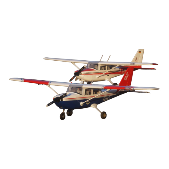
CESSNA 172
Instruction manual / Montageanleitung
SPECIFICATIONS
Wingspan:......................................1730mm
Length (installed motor) .................1190mm
Electric Motor:.................................800Watt
Glow Engine:.................... .55 2-T / .72 4-T
RTF Weight: 3100 - 3450g (will vary with
equipment use).
Radio:....................6 Channel / 6-7 Servos
Function: Ailerons-Elevator-Rudder-Throttle
Flaps.
WARNING! This radio controlled model is NOT a toy. If modified or flown carelessly it could go out of controll and
cause serious human injury or property damage. Before flying your airplane, ensure the air field is spacious enough.
Always fly it outdoors in safe areas and seek professional advice if you are unexperienced.
ACHTUNG! Dieses ferngesteuerte Modell ist KEIN Spielzeug! Es ist für fortgeschrittene Modellflugpiloten bestimmt,
die ausreichende Erfahrung im Umgang mit derartigen Modellen besitzen. Bei unsachgemässer Verwendung kann
hoher Personen- und/oder Sachschaden entstehen. Fragen Sie in einem Modellbauverein in Ihrer Nähe um
professionelle Unterstätzung, wenn Sie Hilfe im Bau und Betrieb benötigen. Der Zusammenbau dieses Modells ist
durch die vielen Abbildungen selbsterklärend und ist für fortgeschrittene, erfahrene Modellbauer bestimmt.
Radio control model / Flugmodel
1730mm Wingspan
ALL BALSA, PLYWOOD CONSTRUCTION AND ALMOST READY TO FLY
Advertisement
Table of Contents

Subscribe to Our Youtube Channel
Related Manuals for VQ Model 18009


Summary of Contents for VQ Model 18009
- Page 1 CESSNA 172 Radio control model / Flugmodel 1730mm Wingspan ALL BALSA, PLYWOOD CONSTRUCTION AND ALMOST READY TO FLY Instruction manual / Montageanleitung SPECIFICATIONS Wingspan:........1730mm Length (installed motor) ....1190mm Electric Motor:.........800Watt Glow Engine:.....55 2-T / .72 4-T RTF Weight: 3100 - 3450g (will vary with equipment use).
- Page 2 REQUIRED FOR OPERATION (Purchase separately) Aileron: 50cmx2 pcs Aileron: “Y”x1pcs Flap: 30cmx2 pcs Rx battery pack: 20cmx1 pcs Standard Mini (19g) 800W Brushless Motor 8 channels radio Elevator : 1 standard servo .62 ~.72 - 4 cycle .55 - 2 cycle Rudder: 1 standard servo Aileron: 2 mini servo Flaps: 2 mini servo...
- Page 3 SAFETY NOTES BEFORE ASSEMBLING This model is highly pre-fabricated and can be built in a very short time. However, the work which you have to carry out is important and must be done carefully. The model will only be strong and fly well if you complete your tasks competently - so please work slowly, accurately and check every joints, maybe apply more glue to be safe.
- Page 4 Insert the 3mm white nylon tube and 1.2x550mm nose gear 1- Nose gear pushrod into the fuselage as shown. The canopy hatch should be removed to make installation of other parts easier. Nose gear push rod Step 2 Nose gear arm Step 3 Step 1 3x25mm hex bolt...
-
Page 5: Main Landing Gear
2- Main landing gear 4x20mm nylon bolt ..1 Fuselage - Bottom view 4x20mm nylon bolt NOTE: If necessary, you can drill four holes in the aluminum landing gear wider to make installation easier. Aluminum main landing gear Aluminum main landing gear 3x15mm screw 3x15mm screw 3x15mm hex bolt... - Page 6 3- Main landing gear...
- Page 7 4- Main landing gear 2x8mm screw ..16 4mm nut 4mm nut 4x45mm screw Aluminum landing gear 75mm wheel ...2 4X45mm screw ...2 4mm nut ....4 4mm washer ....6...
-
Page 8: Glow Engine Installation
5- GLOW ENGINE INSTALLATION B’ ! Align the mark on both engine mount beams with the mark on the Fire-wall. B’ Attach the engine mount beams onto the fire-wall so the distance between of two engine mount beams is “A”,and B=B’ as show. B’... - Page 9 6- GLOW ENGINE INSTALLATION Position the engine to the engine mounts so the distance from the prop hub to the fire-wall is 127mm. Mark the engine mount beams where the four holes are to be drilled. 127mm Remove the engine and drill a 3mm holes through the beam at each of the four marks made above.
- Page 10 7- FUEL TANK After confirming the direction . Insert and tighten the To muffler screw. 3x35 mm screw Filler tube To engine Blow Water Checking for leaks - block the vents and blow into the feed - if in doubt submersing the tank in a blow of water will show up any problems.
- Page 11 8- Electric motor mount Using a aluminum motor mounting plate as a template, mark the plywood motor mounting plate where the four holes are to be drilled. Step 1 Step 2 Remove the aluminum motor mounting plate and drill a 3mm hole through the plywood at each of the four marks marked .
- Page 12 9- Electric motor mount 5x80mm bolt..4 5mm nut..12 5mm washer...16 Attach the four 5x80mm bolts and nuts to the fire-wall as shown. Step 7 Secure the Motor to the wooden motor mounting plate using the 3mm bolt / nut...4 Step 6 four 3mm bolts.
-
Page 13: Horizontal Stabilizer
10- Horizontal stabilizer Insert the horizontal stabilizer Cut off the gray covering into the slot on the fuselage, if necessary, use sander to widen the slot to make this easier. A’ A=A’ Check the alignment of the horizontal stabilizer by measuring from the fixed point along the center line of the fuselage to the trailing edge of the horizontal stabilizer The distance must be equal on both sides. - Page 14 11- Horizontal stabilizer Check the alignment of the horizontal stabilizer. When you are satisfied with the alignment, use a pencil to trace around the top and bottom of the stabilizer where it meets the fuselage. Cut away only the covering both sides.
-
Page 15: Vertical Stabilizer
12- Horizontal stabilizer Thin CA Again, slide the horizontal stabilizer into the slot on the fuselage. Check the alignment of the horizontal stabilizer (B=B’). B’ Thin CA B=B’ The distance must be equal on both sides (B=B’). If not, adjust the stabilizer until the measurement are When you are satisfied with the alignment, glue the both sides of the same. - Page 16 14- Vertical stabilizer Trial fit the vertical stabilizer in place on the fuselage. Check the alignment of the vertical stabilizer with the fuselage. When you are satisfied with the alignment, use a pencil to carefully trace around the left and right of the vertical stabilizer where it meets the fuselage.
- Page 17 15- Vertical stabilizer Use a small glue faucet, Apply the thin CA glue on ! Securely glue together. If coming off the vertical stabilizer where it contacts the fuselage during fly, you lose control of your air plane. (both the left and right sides). Thin CA Step 6 Apply thin CA glue on the top and bottom of the hinges...
-
Page 18: Control Horn
16- Control horn 17- Connector Threadlocker Connector ..1 Connector ..4 2x950mm rod/clevis ...3 1.2x550mm throttle rod ..2 2x100mm rod ..1... - Page 19 17- Linkages...
- Page 20 18- Linkages...
- Page 21 19- Pilot’s seat...
- Page 22 20- Cowl Insert the cowl onto the fuselage so that the distance from the prop hub of engine to the front of the cowl is 2mm as shown. 2.5x10mm screw ..6...
- Page 23 21- Aileron and Flap servo Using the thread (pre-installed at factory) to slide the aileron extension cord into the wing half. Flap servo hatch 50cm Extension cord FLAP SERVO HATCH - BOTTOM VIEW Hard wood servo mount 1.5mm IMPORTANT: To be safe, you must attach the four screws Thin CA as shown in this picture.
- Page 24 22- Control horn and linkages 2x8mm screw ..4 Thin CA 2x8mm Thread locker Plastic control horn with screws ..1 Set Plastic control horn ..1 Connector ..1 FLAP LINKAGE Thread locker...
- Page 25 23- Dowel 6x20mm wooden dowel 6x20mm wooden dowel Note: The wooden dowels must be perpendicular with the root rib. Thin CA...
-
Page 26: Joining The Wing
24- Joining the wing Slowly, push the aluminum tube through the fuselage in a spiral. Carefully, push each wing close to the fuselage. Once the wings is close to the fuselage, hold it in place with two 7mm nylon bolts...2... - Page 27 25- Wing brace Make a 10mm round hole on the plastic cover as shown. Then thread these two plastic cover into the wing brace as shown. Note: The blind nut is already installed inside STEP 3x15mm hex bolt STEP 3x12mm screw Attach the 3mm hex bolt on the fuselage first (Step 1).
- Page 28 26- Wing brace 2x8mm 2x8mm screw 2x8mm screw ..16 27- Antenna Thin CA Antenna mount. 3mm White nylon tube Step 1 Thin CA Step 5...
-
Page 29: Control Surface
29- Balance THE CENTER OF GRAVITY IS LOCATED 67 - 71mm BACK FROM THE LEADING EDGE OF THE WING, AT THE FUSELAGE. BALANCE A PLANE UPSIDE DOWN WITH THE FUEL TANK EMPTY. 67-71mm 1- Mount the wing to the fuselage. Using a couple of pieces of masking tape, place them on the top side of the wing (67-71mm) back from the leading edge, at the fuselage sides. - Page 30 31- Decor CIVIL AIR PATROL VERSION FLIGHT CENTER-DE. VERSION Sticker Sticker Sticker Sticker IMPORTANT: Please do not clean your model with strong solvent or pure alcohol, only use kerosene to keep the colour of your model not fade.
Need help?
Do you have a question about the 18009 and is the answer not in the manual?
Questions and answers