Table of Contents
Advertisement
Quick Links
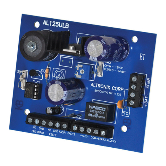
The AL125ULB is a power-limited power supply/charger that converts a low voltage AC input into two individually PTC
protected 12VDC or 24VDC outputs (see specifications). They are intended for use in applications requiring UL Listing
for Access Control (UL 294) and applications requiring an interface with Fire Alarm Control Panels.
Agency Listings:
• UL Recognized component.
• NFPA 101 (Life Safety)
Input Rating:
• 24VAC/40VA.
Output Rating:
• 12VDC or 24VDC selectable, Class 2 Rated
power-limited outputs.
• 1A total supply current @ 12VDC or 24VDC.
• Filtered and electronically regulated output.*
*Note: When unit is powered by battery back up (AC Fail condition), the voltage range is 9.3V-13.2V and
19.55V-26.4V for 12 and 24 volt operation respectively.
Output VDC
Switch Position
12VDC
SW2 OFF
24VDC
SW2 ON
Output
12VDC/4AH Battery
24VDC/4AH Battery
The units should be installed in accordance with article 760 of The National Electrical Code and NFPA 72 as well as all
applicable Local Codes.
See Terminal Identification Chart on page 2 for a description of each terminal function.
1. Mount unit in the desired location/enclosure.
2. Connect 24VAC from a UL Listed 40VA plug-in transformer to the terminals marked [XFMR].
Keep power-limited wiring separate from non power-limited wiring
(115VAC 50/60Hz Input, Battery Wires). Minimum 0.25" spacing must be provided.
3. Measure output voltage before connecting any devices to ensure proper operation.
Improper or high voltage will damage these devices.
4. Set the desired DC output voltage by setting switch SW2 (Fig. 1a - Application Diagram, pg. 2) to the appropriate
position (Power Supply Output Specifications Table, pg. 1).
5. Connect Fail-Safe locking devices to the terminals marked [COM-- and LOCK+]. Connect Fail-Secure locking
devices to the terminals marked [COM-- and STRIKE+] (Fig. 1 - Application Diagram, pg. 2).
6. Connect normally open access control device (i.e. cardreader, request to exit device, access control system) to the
terminals marked TRG INPUT [NO, GND] (Fig. 1 - Application Diagram, pg. 2).
7. Connect FACP interface to the terminals marked [FACP1 and FACP2]. Wire the 2.2K resistor (supplied) in series
for a normally closed input or in parallel for a normally open input (Fig. 1 - Application Diagram, pg. 2). If
required, set the latching FACP interface mode by closing SW1 (Fig. 1a - Application Diagram, pg. 2), and connect
a normally open reset device to the terminals marked RESET [NO, GND].
AL125ULB
Access Control Power Supply/Charger
Overview:
Specifications:
Power Supply Output Specifications:
Max. Stand-by Load DC
1A
1A
Stand-by Specifications:
4 hr. of Stand-by and
5 min. of Alarm
Stand-by = 0.5A
Alarm = 1A
Stand-by = 0.5A
Alarm = 1A
Installation Instructions:
Battery Backup:
• Built-in charger for sealed lead acid or gel type batteries.
• Maximum charge current: 400mA.
• Automatic switch over to stand-by battery when AC fails.
Special Features:
• "NO" trigger input.
• Supervised Fire Alarm Disconnect (Latching w/reset or
Non-Latching).
Board Dimensions (W x L x H approximate):
3.1" x 3.9" x 1.4" (88.9mm x 99.6mm x 35.56mm).
Max. Alarm Load DC
1A
1A
Output
12VDC/7AH Battery
24VDC/7AH Battery
Battery (optional)
12VDC
24VDC
4 hr. of Stand-by and
5 min. of Alarm
Stand-by = 1A
Alarm = 1A
Stand-by = 1A
Alarm = 1A
Advertisement
Table of Contents

Related Manuals for Altronix AL125ULB


Summary of Contents for Altronix AL125ULB
- Page 1 Access Control Power Supply/Charger Overview: The AL125ULB is a power-limited power supply/charger that converts a low voltage AC input into two individually PTC protected 12VDC or 24VDC outputs (see specifications). They are intended for use in applications requiring UL Listing for Access Control (UL 294) and applications requiring an interface with Fire Alarm Control Panels.
- Page 2 COM-- STRIKE+ LOCK+ FACP Altronix is not responsible for any typographical errors. 140 58th Street, Brooklyn, New York 11220 USA, 718-567-8181, fax: 718-567-9056 website: www.altronix.com, e-mail: info@altronix.com. Lifetime Warranty, Made in U.S.A. MEMBER IIAL125ULB - Rev. 100710 B17P MAG LOCK...
Need help?
Do you have a question about the AL125ULB and is the answer not in the manual?
Questions and answers