Table of Contents
Advertisement
Quick Links
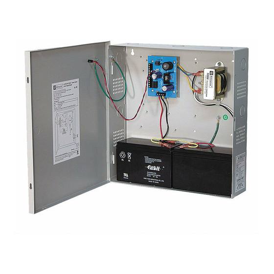
AL125UL Series
Access Control Power Supply/Chargers
Installation Guide
Models Include:
AL125UL
- includes power supply, transformer,
cam lock, and enclosure.
- 8.5" x 7.5" x 3.5"
(215.9mm x 190.5mm x 88.9mm).
- Accommodates one (1) 12VDC/4AH battery.
AL125ULX
- includes power supply, transformer,
cam lock, and enclosure
- 13.5" x 13" x 3.25"
(342.9mm x 330.2mm x 82.6mm).
- Accommodates up to
two (2) 12VDC/7AH batteries.
Rev. 050803
AL125ULE
- includes power supply, cam lock,
and enclosure.
- 8.5" x 7.5" x 3.5"
(215.9mm x 190.5mm x 88.9mm).
- Accommodates up to two (2)
12VDC/4AH batteries.
AL125ULP
- includes power supply, 24VAC/40VA
plug-in transformer, cam lock, and enclosure.
8.5" x 7.5" x 3.5"
(215.9mm x 190.5mm x 88.9mm).
- Accommodates one (1) 12VDC/7AH battery or
two (2) 12VDC/4AH batteries.
More than just power.
TM
Advertisement
Table of Contents

Related Manuals for Altronix AL125UL Series


Summary of Contents for Altronix AL125UL Series
-
Page 1: Installation Guide
AL125UL Series Access Control Power Supply/Chargers Installation Guide Models Include: AL125UL AL125ULE - includes power supply, transformer, - includes power supply, cam lock, cam lock, and enclosure. and enclosure. - 8.5” x 7.5” x 3.5” - 8.5” x 7.5” x 3.5”... -
Page 2: Specifications
Overview: Altronix AL125UL Series power-limited Power Supply/Chargers convert 115VAC 50/60Hz input into two individually PTC protected auto-resettable 12VDC or 24VDC outputs (see specifications). They are intended for use in applications requiring UL Listing for Access Control (UL294) and applications requiring an interface with Fire Alarm Control Panels. -
Page 3: Installation Instructions
[LOCK+] and supplied to the terminal marked [STRIKE +]. RESET Momentary short between these terminals would end latching FACP interface condition. NO, GND Feature active only if latching FACP is selected (SW1 ON). + BAT – Stand-by battery connections. AL125UL Series - 3 -... - Page 4 Expected battery life is 5 years; however, it is recommended changing batteries in 4 years or less if needed. LED Diagnostics: Power Supply Status Normal function. No DC output. Slow Blink Loss of AC. Rapid Blink Unit is triggered, awaiting reset. Fire alarm interface activated. - 4 - AL125UL Series...
- Page 5 AL125UL Series - 5 -...
- Page 6 Notes: - 6 - AL125UL Series...
- Page 7 (15.24mm) (31.75mm) (153.67mm) 1.125” 1.125” (28.575mm) (28.575mm) 2” (50.8mm) 2” (50.8mm) 8.125” (206.375mm) 1” 1” (25.4mm) (25.4mm) 6.05” 0.6” 0.6” 1.25” (153.67mm) (15.24mm) (15.24mm) (31.75mm) 3.5” (88.9mm) 1” (25.4mm) 1” 5.25” 1” (25.4mm) (133.35mm) (25.4mm) AL125UL Series - 7 -...
- Page 8 (267mm) (25mm) Altronix is not responsible for any typographical errors. 140 58th Street, Brooklyn, New York 11220 USA | phone: 718-567-8181 | fax: 718-567-9056 website: www.altronix.com | e-mail: info@altronix.com | Lifetime Warranty | Made in U.S.A. MEMBER IIAL125ULseries C20R - 8 -...
Need help?
Do you have a question about the AL125UL Series and is the answer not in the manual?
Questions and answers