Advertisement
M Series
Multi-Output
Power Supply/Chargers
Installation Guide
Models Include:
• AL300ULM
- 2.5A @ 12VDC or 24VDC.
• AL600ULM
- 6A @ 12VDC or 24VDC.
• AL1024ULM
- 10A @ 24VDC.
Models AL300ULM, AL400ULM, and AL600ULM can be built in a larger enclosure.
For a red enclosure add an "R" suffix to the part #, e.g. AL300ULMR
Add an "X" suffix to the part #, e.g. AL400ULMX
• AL400ULM
- 4A @ 12VDC or 3A @ 24VDC.
• AL1012ULM
- 10A @ 12VDC.
Rev. 102612
Advertisement
Table of Contents

Related Manuals for Altronix AL600ULM


Summary of Contents for Altronix AL600ULM
-
Page 1: Installation Guide
- 10A @ 24VDC. For a red enclosure add an “R” suffix to the part #, e.g. AL300ULMR Models AL300ULM, AL400ULM, and AL600ULM can be built in a larger enclosure. Add an “X” suffix to the part #, e.g. AL400ULMX... -
Page 2: Specifications
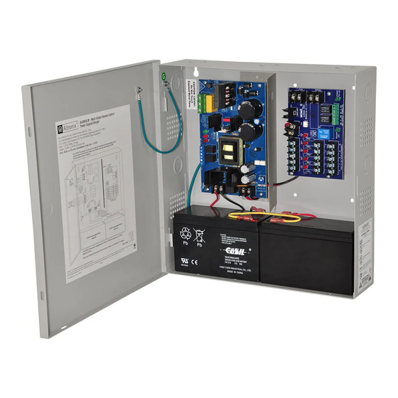
Overview: Altronix M Series multi-output access control power supply/chargers are specifically designed for use with access control systems and accessories. These units convert a 115VAC, 60Hz input into five (5) individually protected 12VDC or 24VDC outputs (see specifica- tions). Each output will route power to a variety of access control hardware devices including Mag Locks, Electric Strikes, Magnetic Door Holders, etc. -
Page 3: Installation Instructions
2. Set output voltage: AL300ULM, AL400ULM (Fig. 1c, pg. 5) and AL600ULM (Fig. 2b, pg. 6) set desired DC output voltage by setting switch SW1 to the appropriate position on the power supply board. AL1012ULM is 12VDC only. AL1024ULM is 24VDC only. -
Page 4: Output Voltage And Stand-By Specification Charts
Stand-by = 1.0A Stand-by = 300mA 24VDC/40AH Battery Alarm = 3.0A Alarm = 3.0A Alarm = 3.0A AL600ULM 4 hr. of Stand-by & 24 hr. of Stand-by & 60 hr. of Stand-by & Output Switch Position 5 Minutes of Alarm... - Page 5 Fig. 1 - AL300ULM, AL400ULM CAUTION: De-energize unit prior to servicing. For continued protection against risk of electric shock and fire hazard replace fuses with the same type and rating (see marking on the board). Do not expose to rain or moisture. Fig.
- Page 6 Fig. 2 - AL600ULM CAUTION: De-energize unit prior to servicing. For continued protection against risk of electric shock and fire hazard replace fuse with the same type and rating. Do not expose to rain or moisture. Divider Fire Alarm Interface...
- Page 7 Fig. 3 - AL1012ULM CAUTION: De-energize unit prior to servicing. For continued protection against risk of electric shock and fire hazard replace fuses with the same type and rating. Do not expose to rain or moisture. Earth non power-limited Door ground Fig.
- Page 8 Fig. 4 - AL1024ULM CAUTION: De-energize unit prior to servicing. For continued protection against risk of electric shock and fire hazard replace fuses with the same type and rating (see marking on the board). Do not expose to rain or moisture. Fig.
-
Page 9: Maintenance
Maintenance: Unit should be tested at least once a year for the proper operation as follows: Output Voltage Test: Under normal load conditions the DC output voltage should be checked for proper voltage level (Output Voltage and Stand-by Specification Charts, pg. 4). Battery Test: Under normal load conditions check that the battery is fully charged, check specified voltage at the battery terminals and at the board terminals marked [+ BAT --- ] to ensure that there is no break in the battery connection wires. - Page 10 AL400ULM - 12VDC @ 4A or 24VDC @ 3A to MOM5 board (power-limited). + DC – AL600ULM - 12VDC/24VDC @ 6A to MOM5 board (power-limited). AL1012ULM - 12VDC @ 10A to MOM5 board (power-limited). AL1024ULM - 24VDC @ 10A to MOM5 board (power-limited).
-
Page 11: Typical Application Diagrams
- DC INPUT+ DC VOLTAGE INPUT FROM FACP SIGNALING OUTPUT OR ACCESS (--) MOM5_S CONTROL DEVICE MOM5_S ALTRONIX CORP. ALTRONIX CORP. BROOKLYN, NY 11220 BROOKLYN, NY 11220 MADE IN USA MADE IN USA EOL 2.2K N.O. INPUT FROM FACP OR ACCESS... - Page 12 Typical Application Diagrams (cont’d.): Fig. 8 MOM5 module shown with with wet and/or MOM5 module shown with with wet and/or dry dry normally open fire alarm trigger inputs normally closed fire alarm trigger inputs (Latching with Manual Reset): (Latching with Manual Reset): DC VOLTAGE INPUT FROM FACP DC VOLTAGE INPUT...
-
Page 13: Appendix A - Ul Listed Compatible Devices
Appendix A - UL Listed Compatible Devices A.1 Four (4) Wire Smoke Detectors Table A-1 below lists four (4) wire smoke detectors compatible with AL300ULM, AL400ULM, AL600ULM, AL1012ULM, and AL1024ULM output. System Sensor Max Stand-by Alarm Current Detector Type Smoke Detector/Base... - Page 14 AL1024ULM Battery Size Calculation Worksheet. A. AL1024ULM internal current consumption (stand-by) ______________ 0.13 A B. Load current consumption (stand-by) ______________ A C. Stand-by time required (hours) ______________ H D. Battery capacity required for stand-by (A+B)*C ______________ AH E. AL1024ULM internal power consumption (Alarm) ______________ 0.13 A F.
- Page 15 Enclosure Dimensions (BC300): AL300ULM, AL400ULM, AL600ULM 13.5” x 13” x 3.25” (342.9mm x 330.2mm x 82.55mm) 1.40” 4.85” 4.85” 1.40” (36mm) (123mm) (123mm) (36mm) 1.20” (31mm) 3.25” (83mm) 12.5” (318mm) 1.20” 1.20” 0.75” 0.75” (31mm) 11.0” (31mm) (19mm) (19mm) (279mm) 0.9375”...
- Page 16 (117.22mm) (38.1mm) Altronix is not responsible for any typographical errors. 140 58th Street, Brooklyn, New York 11220 USA | phone: 718-567-8181 | fax: 718-567-9056 web site: www.altronix.com | e-mail: info@altronix.com | Lifetime Warranty | Made in U.S.A. IIMseries E02Q MEMBER...
Need help?
Do you have a question about the AL600ULM and is the answer not in the manual?
Questions and answers