Lumag MD500 Operator's Manual
Mini dumper
Hide thumbs
Also See for MD500:
- Operator's manual (24 pages) ,
- Operating instructions manual (32 pages)
Advertisement
Quick Links
Distribution Limited
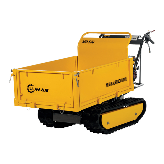
Mini Dumper
Operator's Manual
MD500
FOR YOUR SAFETY
FOR YOUR SAFETY
FOR YOUR SAFETY
READ AND UNDERSTAND THE ENTIRE MANUAL
READ AND UNDERSTAND THE ENTIRE MANUAL
Ensure you read and understand how to operate
BEFORE OPERATING THIS MACHINE
the machine safely. Check your machines oil
BEFORE OPERATING THIS MACHINE
levels before every use.
Advertisement

Subscribe to Our Youtube Channel
Related Manuals for Lumag MD500


Summary of Contents for Lumag MD500
- Page 1 Distribution Limited Mini Dumper Operator’s Manual MD500 FOR YOUR SAFETY FOR YOUR SAFETY FOR YOUR SAFETY READ AND UNDERSTAND THE ENTIRE MANUAL READ AND UNDERSTAND THE ENTIRE MANUAL Ensure you read and understand how to operate BEFORE OPERATING THIS MACHINE the machine safely.
- Page 3 Clutch & Steering Handles Check Function 1 – First service only, 2 = Should be carried out by your Lumag Dealer, 3 = May need to be done more often in dusty areas & 4 = Replace paper element only...
- Page 8 IMPORTANT INSTRUCTIONS WATCH OUT! Read before assembly and before bringing the entire text of the manual. Familiarize yourself with this manual with the unit, its proper use and the safety instructions. Keep this safe place so that you are readily available information. If you pass the device to other people, please hand over the complete manual from with.
- Page 9 CONTENT introduction Intended Use safety instructions General Safety Rules Workspace Personal security Fuel security Machine utilization and maintenance maintenance Specific Safety Rules Warning and information symbols used delivery Assembly Features and Controls business Filling with fuel Starting the engine Neutral Stopping the motor maintenance preventive maintenance...
- Page 10 INTENDED USE SAFETY INSTRUCTIONS SAFETY INSTRUCTIONS INTRODUCTION Keep avoiding grounded conductive objects such as tools, from exposed live parts and connections to sparking and arcing. These events could ignite fumes or Your new Mini Dumper has been built to high standards for reliability, ease of use and safety. vapors.
- Page 11 SAFETY INSTRUCTIONS SAFETY INSTRUCTIONS Safety reference. Insufficiently informed will endanger themselves and others due to Keep avoiding grounded conductive objects such as tools, from exposed live improper use. parts and connections to sparking and arcing. These events could ignite fumes or vapors.
- Page 12 SAFETY INSTRUCTIONS 3.2 Workspace DANGER Internal combustion engines during operation and fueling a special hazard. Always read and follow the warnings and to the additional safety instructions given in parallel later in this manual. Failure to do so could result in serious injury or death. Do not allow engine start indoors, garages or enclosed areas or run.
- Page 13 SAFETY INSTRUCTIONS SAFETY INSTRUCTIONS are. Make sure that all nuts, bolts, etc. are tight. Keep avoiding grounded conductive objects such as tools, from exposed live Damaged guards and covers must be intended repaired by an authorized service parts and connections to sparking and arcing. These events could ignite fumes or workshop or replaced, unless otherwise specified in the instructions.
- Page 14 SAFETY INSTRUCTIONS Keep avoiding grounded conductive objects such as tools, from exposed live parts and connections to sparking and arcing. These events could ignite fumes or vapors. Switch off the engine and always let it cool before filling the fuel. Do not remove the cap of the fuel tank or fuel fill in hot or running motor.
- Page 15 SAFETY INSTRUCTIONS SAFETY INSTRUCTIONS Use only approved by the manufacturer, and accessories. Failure to comply Keep avoiding grounded conductive objects such as tools, from exposed live may result in injury. parts and connections to sparking and arcing. These events could ignite fumes or Wait for the machine.
- Page 16 SAFETY INSTRUCTIONS would bring laying in danger. keep bystanders, children and animals at least 22 meters away. When approaching stop operation immediately. Do not climb on the Tilting and do not transport people with it. put the machine, especially when loaded, never could yield to an unstable ground. In front disengage the engine is started.
- Page 17 SYMBOLS SYMBOLS USED ALARM AND SYMBOLS NOTE The machine is supplied without engine oil. Before the first start is thus fill the first motor oil. Failure to comply may result in irreparable damage to the engine. DANGER Health and explosion due to engine ■...
- Page 18 SYMBOLS SYMBOLS Trailer loading never flip on soft ground or in an inclined position Warning from flying objects Bystanders keep. Warning of hot surfaces! Contact can cause burns. perform maintenance, servicing and cleaning work when the engine is cold. Risk of injury. Hazard due to rotating parts such as chain or belt drive. Hands and feet away.
- Page 19 DELIVERY DELIVERY The all-terrain Mini-dumper is partially assembled them and come in carefully wrapped packages. Once you have all the parts removed from the package, you should be: Ready mounted machine unit handlebar assembly tilt handle Extendable lift Engine Guard M10 20 Extendable lift M8 25...
- Page 20 ASSEMBLY ASSEMBLY ASSEMBLY Follow the instructions to install the machine in minutes. Place the bottom plate in the mounting bracket. Align the holes with the mounting bracket. Insert the pin through the holes and secure each side with a flat washer and a nut.
- Page 21 ASSEMBLY Position the motor protection in the mounting bracket and align them with the mounting bracket holes from. Back up the left side wall with two M8x30 screw heads, four washers and two nuts. NOTE Mount the tilt handle on the right side panel. Align the holes and fasten with two M8x35 hex screws, four washers and two nuts.
- Page 22 ASSEMBLY Position the motor protection in the mounting bracket and align them with the mounting bracket holes from. Back up the left side wall with two M8x30 screw heads, four washers and two nuts. NOTE Mount the tilt handle on the right side panel. Align the holes and fasten with two M8x35 hex screws, four washers and two nuts.
- Page 23 FUNCTIONS AND CONTROLS FUNCTIONS AND CONTROLS Engine switch throttle control lever right clutch lever Tilting steering lever left lever tilt handle Chain gearbox motor switch With the engine switch the ignition system on and off. Allow the engine to run, the engine switch to ON (ON) has to be connected. When the engine switch to OFF (OFF) is switched, the motor is turned off.
- Page 24 FUNCTIONS AND CONTROLS BUSINESS gear lever With this lever, the forward and backward movements of the machine are controlled. tilt handle With the tilt handle the tilting of the tilting is controlled. For lifting of the tilting of the handle is pushed forward.
- Page 25 BUSINESS 8.2 Starting the engine A detailed description of the engine operation and all related warnings and measures found in the separate, included with the Mini-dumper engine manual. During cold starts comply with the following procedure: turning the choke lever to the motor in the closed position. Move the throttle lever on the handle in the central switching position.
- Page 26 OPERATION / MAINTENANCE comes in considerable slopes when driving over bumps, holes and steps. ■ When the clutch lever is released, stops and automatically brakes the machine. ■ If the machine is stopped on steep slopes, one of the chains with a wedge must be secured.
- Page 27 MAINTENA 9.1 preventive maintenance Stop the engine and disengage all control levers. The engine must be cold. Check overall condition of the device. check for loose screws, misalignment or blockage of moving parts and other conditions that could affect the safe operation. Remove all dirt and other of chain and device materials present.
- Page 28 MAINTENANCE 9.5 Tightening the chains With increasing service life, the chains may be loose. Operating with loose chains can cause these away slip over the drive wheel and cause them to jump out of its housing, or no longer work safely and so can damage the case. Proceed as follows for checking the tightness of the chains: Machine on a flat surface with the compact surface, preferably asphalt or stone floor filters.
- Page 29 MAINTENA NOTE If the set screw does not allow further adjustment more, the chains should be replaced. Tilting bring them back to the starting position. 9.6 Replacement of the chains Check the condition of the chains regularly. If a chain is broken or become fibrous, they should be replaced soon as possible.
- Page 30 STORAGE / TRANSPORT 10. STORAGE DANGER Do not store engine with fuel in a non-ventilated area, may come into contact in the fuel vapors with flame, spark, pilot lamps or other sources of ignition. If the mini-dump unused state for more than 30 days, the following steps are designed for storing the device to perform: Drain fuel tank completely.
- Page 31 TRANSPORT / ACCESSORIES ■ During transport always switch off the engine! ■ Make sure that Loading area and side walls are fixed. ■ Carrying the device in a horizontal position to prevent fuel or oil leakage. ■ When transporting over long distances, the fuel tank is completely emptied. ■...
- Page 32 TROUBLE 12. TROUBLE disorder root cause remedy Spark plug cable attach the spark plug disconnected. wire to the spark plug. Lack of fuel or old fuel. fill with clean, fresh gasoline. not choke in the open Move the throttle lever to position.
- Page 33 TECHNICAL SPECIFICATIONS 13. TECHNICAL SPECIFICATIONS model MD-500 drive motor 1 cylinder 4-cycle OHV engine engine power 4.8 kW (at 3600 U / min) capacity 196 cc Working speed Gear 1 forward - 1.6 km / h Gang 2 forward - 2.9 km / h Gear 3 forward - 3.6 km / h Gang 1 reverse - 1.2 km / h starting device...
- Page 34 Please label the shipping box are clearly labeled SERVICE NUMBER to ensure fast classification. Warranty work be carried out by our LUMAG service workshop. Possible defects within the warranty period due to material or manufacturing errors, if they occur despite proper use and care of the unit to eliminate by a rectification.
- Page 35 EC DECLARATION OF CONFORMITY 15. EC DECLARATION OF CONFORMITY Under the provisions of the EC directives – Machinery Directive 2006/42 / EC – Electromagnetic compatibility 2004/108 / EC declared the Company: LVG Hartham GmbH Robert-Bosch-Ring 3 D-84375 Kirchdorf / Phone: 0049 / (0) 8571/92 556-0 Fax: 0049 / (0) 8571/92 556-19 that the product...
- Page 36 PARTS OF THE TOOL 16. PARTS OF THE TOOL...
- Page 37 PARTS OF THE TOOL Tilting...
- Page 38 PARTS OF THE TOOL gearbox...
- Page 39 LVG GmbH Hartham Robert-Bosch-Ring 3 D-84375 Kirchdorf Phone: +49 (0) 85 71/92 556 - 0 Fax: +49 (0) 85 71/92 556 - 19...
- Page 40 Unit 1-3, Hatchmoor Industrial Estate, Hatherleigh, Okehampton, Devon EX20 3LP Lumag Distribution Limited Company Number: 09267547 VAT Number: GB154566788 Hatherleigh www.lumag-gb.co.uk 01837 811741 Plant and Tool Hire is a trading name of Lumag Distribution LTD Lumag Distribution Limited Company Number: 09267547 VAT Number: GB154566788 Hatherleigh...
Need help?
Do you have a question about the MD500 and is the answer not in the manual?
Questions and answers