Table of Contents
Advertisement
FUNCTION GENERATOR-SERIES
TABLE OF CONTENTS
1.
Safety Summary..............................................
2.
Introduction...................................................
3.
Specification....................................................
4.
Function Description......................................
5.
Usage Description...........................................
6.
Application Note.............................................
7.
Maintenance...................................................
INSTRUCTION MANUAL
2
1
5
7
13
17
23
33
Advertisement
Table of Contents

Related Manuals for GW Instek GFG-8215A


Summary of Contents for GW Instek GFG-8215A
- Page 1 FUNCTION GENERATOR-SERIES INSTRUCTION MANUAL TABLE OF CONTENTS SAFETY SUMMARY………………………………………. INTRODUCTION…………………………………………… SPECIFICATION……………………………………………. FUNCTION DESCRIPTION.………………………………. USAGE DESCRIPTION……………………………………. APPLICATION NOTE……………………………………… MAINTENANCE……………………………………………...
- Page 2 FUNCTION GENERATOR-SERIES INSTRUCTION MANUAL 1.SAFETY TERMS AND SYMBOLS Please take a moment to review these safety terms and symbols which may appear in this manual or on Equipment to prevent damage to the Function Generators. WARNING. Warning statements identify condition or practices that could result in injury or loss of life.
- Page 3 FUNCTION GENERATOR-SERIES INSTRUCTION MANUAL DANGER High Voltage ATTENTION refer to Manual Protective Conductor Terminal (ground) Earth Terminal Frame or Chassis Terminal...
- Page 4 FUNCTION GENERATOR-SERIES INSTRUCTION MANUAL FOR UNITED KINGDOM ONLY NOTE: This lead/appliance must only be wired by competent persons WARNING: THIS APPLIANCE MUST BE EARTHED IMPORTANT: The wires in this lead are coloured in accordance with the following code: Green/ Yellow: Earth Blue: Neutral Brown:...
- Page 5 FUNCTION GENERATOR-SERIES INSTRUCTION MANUAL terminal which is marked with the letter N or coloured Blue or Black. The wire which is coloured Brown must be connected to the terminal marked with the letter L or P or coloured Brown or Red. If in doubt, consult the instructions provided with the equipment or contact the supplier.
-
Page 6: Introduction
ADDITIONAL FEATURES 1.Low distortion waveforms (sine, triangular and square) and ramp signal. 2.Signal output in seven decade stages, 0.5Hz to 5MHz for GFG-8250A/8255A, 0.3Hz to 3MHz for GFG-8215A/8216A/8217A/8219A. 3.Adjustable sweep time and sweep width both in linear and logarithmic modes. - Page 7 FUNCTION GENERATOR-SERIES INSTRUCTION MANUAL 7.A second output for TTL or adjustable CMOS pulses. 8.50 ohm main signal output with DC offset adjustment and 20dB attenuation capability. 9. Supplied with two BNC test leads and AC power cord set. FEATURES COMPARISON TABLE FOR MODELS: MODEL GFG- GFG-...
-
Page 8: Specification
(into 50Ωload) 80%:20%:80% to 1MHz 80%:20%:80% to 1MHz Duty Control Continued variable Continued variable 6 digits LED display Display *GFG-8215A does not have 6 digits LED display display. ±5%+1Hz(at 3.0 position) Range Accuracy ---------------------------- *only for GFG-8215A. 2.Sine Wave ≦1%,0.3Hz~200kHz ≦1%,0.5Hz~100kHz... - Page 9 FUNCTION GENERATOR-SERIES INSTRUCTION MANUAL GFG- GFG- 8215A/8216A/8217A/8219A 8250A/8255A 5.CMOS Output 4Vpp±1Vpp~14.5Vpp 4Vpp±1Vpp~14.5Vpp Level ±0.5Vpp adjustable ±0.5Vpp adjustable ≦120ns ≦120ns Rise or Fall Time 6.TTL Output ≧3Vpp ≧3Vpp Level Fan Out 20 TTL load 20 TTL load ≦25ns ≦25ns Rise or Fall Time 7.VCF Input voltage 0V~10V±1V(100:1)
- Page 10 0.1Hz for 100MHz. Input Impedance 1MΩ/150pF 1MΩ/150pf ≦35mVrms(5Hz~100MHz) ≦35mVrms(5Hz~100MHz) ≦45mVrms(100MHz~150MHz) ≦45mVrms(100MHz~150MHz) Sensitivity *GFG-8215A does not have Frequency Counter function. 13.General Power Source AC115V, 230V±15%,50/60Hz AC115V, 230V±15%,50/60Hz Indoor use, altitude up to 2000m. Ambient Temperature 0℃ to 40℃. Operation Relative Humidity 80%(Maximum).
- Page 11 FUNCTION GENERATOR-SERIES INSTRUCTION MANUAL GFG- GFG- 8215A/8216A/8217A/8219A 8250A/8255A GTL-101×2 GTL-101×2 Accessories *GTL-101×1 for GFG-8215A Instruction manual×1 Instruction manual×1 Dimension 251(W)×91(H)×291(D) m/m 251(W)×91(H)×291(D) m/m Approx. 2.0kgs-GFG-8215A Approx. 2.3kgs-GFG-8250A 2.1kgs-GFG-8216A 2.4kgs-GFG-8255A Weigh 2.15kgs-GFG-8217A 2.2kgs-GFG-8219A Measurement category I is for measurements performed on circuits not directly connected to MAINS.
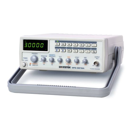
- Page 12 FUNCTION GENERATOR-SERIES INSTRUCTION MANUAL Fig 4.1 FRONT PANEL...
- Page 13 FUNCTION GENERATOR-SERIES INSTRUCTION MANUAL Fig.4-2 REAR PANEL...
-
Page 14: Function Description
FUNCTION GENERATOR-SERIES INSTRUCTION MANUAL 4. FUNCTION DESCRIPTION Power Switch Connect the AC power, then press power switch. Gate Time Press the power switch, Gate time indicator will start Indicator to flash (the gate time of internal counter is 0.01 second). 2a. - Page 15 FUNCTION GENERATOR-SERIES INSTRUCTION MANUAL Table 1(for GFG-8215A/8216A/8217A/8219A) Push bottom 100k 0.3Hz 30Hz 300Hz 3kHz 30kHz 300kHz ∣ ∣ ∣ ∣ ∣ ∣ ∣ Frequency Range 30Hz 300Hz 3kHz 30kHz 300kHz 3MHz Table 2(for GFG-8250A/8255A) Push bottom 100k 0.5Hz 50Hz 500Hz...
- Page 16 FUNCTION GENERATOR-SERIES INSTRUCTION MANUAL 12a. 20dB Attenuation Press the knob to adjust a –20dB output. MANU/SWEEP Press and turn clockwise the knob for MAX frequency Selector and and invert for MIN frequency. (Keep the pointer within Frequency the scale range on the panel.). Adjustment Pull out the knob to start the auto sweep operation;...
- Page 17 (3) The function of item 15, 16-2, 16-3, 17 and 23 can not be applied to GFG-8217A. (4) The function of item 20 for GFG-8216A/8250A can be selected from front panel. (5) The function of item 20 and 21 for GFG-8215A can be selected from front panel.
-
Page 18: Usage Description
FUNCTION GENERATOR-SERIES INSTRUCTION MANUAL 5. USAGE DESCRIPTION These function generators can provide versatile waveforms of high efficiency and convenient operation. Familiarize yourselves with these functions thoroughly through Operation Manual and practice with all accurate operation procedures can lead you to easily master the performance of these Function Generators. - Page 19 FUNCTION GENERATOR-SERIES INSTRUCTION MANUAL 5-2.Triangle, square and sine wave (1) First select Function , and select Range , rotate FREQ , to set the required frequency.(read out from display window). (2) At this moment, connect Output , to oscilloscope for observing output signal, or connect to other experiment circuit.
- Page 20 FUNCTION GENERATOR-SERIES INSTRUCTION MANUAL 5-3.Pulse wave generation (1) First press the key ( ) of Function ; then select Range and rotate FREQ , to set required frequency range. (2) Connect output-terminal to oscilloscope for observing output signal. (3) Pull out and rotate Duty to adjust the width of pulse waveform.
- Page 21 FUNCTION GENERATOR-SERIES INSTRUCTION MANUAL 5-6.Variation of external voltage-controlled frequency This mode of operation allows the user to adjust the frequency of the function generator with an external DC control Voltage. It also provides an easy way for your adjustment. (1) Select Function first, then select Range , rotate FREQ set required frequency range.
- Page 22 FUNCTION GENERATOR-SERIES INSTRUCTION MANUAL 5-8.AM/FM operation (1) Select function first; then select Range , rotate FREQ to set required frequency range. (2) Connect output terminal to oscilloscope for observing output signal. (3) Press MOD and pull out (press) MOD to obtain FM/AM modulation mode.
- Page 23 FUNCTION GENERATOR-SERIES INSTRUCTION MANUAL Figure 2. Figure 3.
-
Page 24: Application Note
FUNCTION GENERATOR-SERIES INSTRUCTION MANUAL 6. APPLICATION NOTE This section describes the application of the Function Generators in details as well as a brief description relating to the block diagram. Only for the essential application method. (A) Trouble-shooting using signal-tracing method. This method is similar to signal replacing way. - Page 25 FUNCTION GENERATOR-SERIES INSTRUCTION MANUAL (D) Using the Square wave test the characteristics of amplifier circuit. It can’t actually explain the transient response of amplifier by using Sine wave for the frequency response curve observation, but using the high order poly-wave, Square wave, instead to display its waveform from the oscilloscope can show up many characteristics of amplifier.
- Page 26 FUNCTION GENERATOR-SERIES INSTRUCTION MANUAL (a) Connect the lines as Figure 7. (b) According to the operation guide in this manual, set Square wave or Pulse wave output. (c) Use the label TTL, CMOS output terminal testing TTL logic circuit. (d) To test CMOS circuit by pulling up the switch of TTL/CMOS, and adjust CMOS level by rotating the switch to set the proper level (e) Use dual-trace scope to show the input-output timing relation judged by the two waves shown in Figure 4.
- Page 27 FUNCTION GENERATOR-SERIES INSTRUCTION MANUAL (1) Series connect a R1 to the network under test as in Figure 9. (2) Get voltage read out in E1, E2, adjust R1 until E2 is equal to one half of E1. (3) Under this frequency, the impedance network is the same as the (G)Act as automatic test of speaker Because there provide the auto feature in this equipment, the output can drive to amplifier for testing the frequency response of speaker.
- Page 28 FUNCTION GENERATOR-SERIES INSTRUCTION MANUAL FIGURE 4...
- Page 29 FUNCTION GENERATOR-SERIES INSTRUCTION MANUAL FIGURE 5...
- Page 30 FUNCTION GENERATOR-SERIES INSTRUCTION MANUAL FIGURE 6...
- Page 31 FUNCTION GENERATOR-SERIES INSTRUCTION MANUAL FIGURE 7 FIGURE 8...
- Page 32 FUNCTION GENERATOR-SERIES INSTRUCTION MANUAL FIGURE 9 FIGURE 10...
- Page 33 FUNCTION GENERATOR-SERIES INSTRUCTION MANUAL FIGURE 11...
-
Page 34: Maintenance
FUSE Rating and Type Rating Input MODEL 115V 230V Watts GFG-8215A T0.315A 250V T0.16A 250V GFG-8216A T0.315A 250V T0.16A 250V GFG-8217A T0.315A 250V T0.16A 250V GFG-8219A T0.315A 250V T0.16A 250V GFG-8250A T0.315A 250V T0.16A 250V... - Page 35 FUNCTION GENERATOR-SERIES INSTRUCTION MANUAL 7-2.Fuse Replacement Procedure When you proceed calibration or maintenance of the Function Generators, if you want to replace the fuse, the upper cover must be removed according to the following steps: 1).The handle must be turned downward 90 degrees first.
- Page 36 FUNCTION GENERATOR-SERIES INSTRUCTION MANUAL 2).Pull apart the handle from the Function Generator. Please turn the handle left and right side slightly, that will make easier to pull off the handle. 3).There are two washers inside of two holes (the joints of handle and case) respectively.
- Page 37 FUNCTION GENERATOR-SERIES INSTRUCTION MANUAL 4).Please use a screwdriver to open the screw located at upper side of rear panel. Therefore, the upper cover can pull toward the backside. In the meantime, the upper cover is moved. Note: If you want to install the upper cover, please reverse above steps. 7-3.
Need help?
Do you have a question about the GFG-8215A and is the answer not in the manual?
Questions and answers