Table of Contents
Advertisement
Quick Links
Advertisement
Chapters
Table of Contents

Related Manuals for GW Instek GPM-8310


Summary of Contents for GW Instek GPM-8310
- Page 1 Digital Power Meter GPM-8310 USER MANUAL Rev. A ISO-9001 CERTIFIED MANUFACTURER...
- Page 2 This manual contains proprietary information, which is protected by copyright. All rights are reserved. No part of this manual may be photocopied, reproduced or translated to another language without prior written consent of Good Will company. The information in this manual was correct at the time of printing. However, Good Will continues to improve products and reserves the rights to change specification, equipment, and maintenance procedures at any time without notice.
-
Page 3: Table Of Contents
TABLE OF CONTENTS Table of Contents SAFETY INSTRUCTIONS ..........5 GETTING STARTED ............10 Characteristics .......... 11 Appearance ..........16 Set Up ............25 BASIC SETTING ............. 28 Setting up measurement range ....29 Setting up measurement status ....33 Setting up System status ...... - Page 4 GPM-8310 User Manual Command List ........149 APPENDIX ..............228 Specifications ......... 229 Status system ......... 239 Dimensions ..........243 Declaration of Conformity ....... 244 Power measurement ....... 245 Introduction to IEC-62301 ....... 247 EUP Directive Lot6 specifications ... 248...
-
Page 5: Safety Instructions
Warning: Identifies conditions or practices that WARNING could result in injury or loss of life. Caution: Identifies conditions or practices that CAUTION could result in damage to the GPM-8310 or to other properties. DANGER High Voltage Attention Refer to the Manual Protective Conductor Terminal... - Page 6 GPM-8310 User Manual Do not dispose electronic equipment as unsorted municipal waste. Please use a separate collection facility or contact the supplier from which this instrument was purchased.
- Page 7 SAFETY INSTRUCTIONS Safety Guidelines Make sure that the voltage input level does not General Guideline exceed AC600V. CAUTION Make sure the current input level does not exceed 20A. Do not place any heavy object on the instrument. Avoid severe impact or rough handling that can ...
- Page 8 GPM-8310 User Manual (Note) EN 61010-1:2010 specifies the measurement categories and their requirements as follows. The GPM-8310 falls under category II 600V. Measurement category IV is for measurement performed at the source of low-voltage installation. Measurement category III is for measurement performed in the building installation.
- Page 9 SAFETY INSTRUCTIONS (Note) EN 61010-1:2010 specifies the pollution degrees and their requirements as follows. The GPM-8310 falls under degree 2. Pollution refers to “addition of foreign matter, solid, liquid, or gaseous (ionized gases), that may produce a reduction of dielectric strength or surface resistivity”.
- Page 10 GPM-8310 User Manual ETTING STARTED This chapter describes the GPM-8310 in a nutshell, including accessories, package contents, its main features and front / rear panel introduction. Characteristics ..............11 Accessories ....................14 Package Contents ..................15 Appearance ..............16 Front Panel ....................16 Main Display Overview ................
-
Page 11: Getting Started
GETTING STARTED Characteristics The GPM-8310 is a high-precision, programmable power meter for using in standby measuring the device with low power such as switching power supplies, transformers, power supplies, adapter and other devices. It equips with a color TFT-LCD screen and also multiple graph displays which are very convenient for reading the measurement results. - Page 12 GPM-8310 User Manual 6 selectable voltage ranges available from 15V to Performance 600V with 0.1% of reading + 0.05% of range. 12 selectable current ranges available from 5mA to 20A with 0.1% of reading + 0.05% of range.
- Page 13 GETTING STARTED Full five-digit measurement. Features Voltage measurement range: 15V ~ 600V or automatic switching Current measurement range: 5mA ~ 20A or automatic switching Maximum accuracy of 0.1% of reading + 0.05% of range 2 main measurement readings and 8 minor ...
-
Page 14: Accessories
GPM-8310 User Manual Accessories Standard Accessories Part number Description 82PM-83100E01 User Manual CD 82GW1SAFE0M01 Safety Instruction Sheet Region dependent Power Cord GTL-209 Test leads: 1x red, 1x black GTL-212 Test leads: 1x yellow, 1x blue Optional Accessories Part number Description... -
Page 15: Package Contents
GETTING STARTED Package Contents Check the contents before using the instrument. Opening the box Main unit Power cord x1 (region Contents dependent) (single unit) Test leads (red x1, black x1, yellow x1, User manual CD blue x1) Safety instruction ... -
Page 16: Appearance
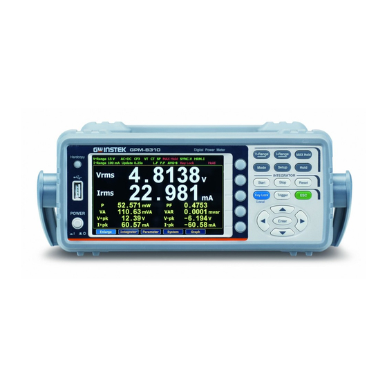
GPM-8310 User Manual Appearance Front Panel Hardcopy Key LCD Display Function Keys Digital Power Meter GPM - 8310 V-Range I-Range MAX Hold Hardcopy Setup Mode Hold INTEGRATOR Stop Start Reset Trigger Key Lock Local : Long Push POWER Enter Soft... - Page 17 GETTING STARTED V-Range key, up/down arrow keys Function Keys and Enter key can be used together to select a voltage range or auto range measurement mode. Also, press and hold the V-Range key to toggle between manual and auto range setting. See page 29. I-Range key, up/down arrow keys and Enter key can be used together to select a current range or auto...
- Page 18 GPM-8310 User Manual Press this key to toggle to key lock. In Remote control mode, press this button to switch to local mode. See page 90. This button is used to enter the menu, Enter Key confirm the settings and switch...
-
Page 19: Main Display Overview
GETTING STARTED Main Display Overview Sync Max. Hold Voltage Range Mode Remote Source External Update Rate Average Display Hold Current Range CT SF Peak Voltage Peak Current Line Filter Harmonic Calculation Main Measurement Measure Display Storage Key Lock Minor Measurement Frequency Display Filter... - Page 20 GPM-8310 User Manual External voltage magnification VT Ratio State (On/Off) External current magnification CT Ratio State (On/Off) External power magnification Power Ratio (On/Off) State Remote control mode (On/Off) Remote Voltage and current filters (On/Off) Line Filter Frequency filters (On/Off) Frequency Filter...
- Page 21 GETTING STARTED Display the measurement result of 2 major and 8 Standard Display minor measurement parameters Mode Display the measurement result of 4 major Simple Display measurement parameters Mode Secondary menus Display secondary function menu Enlarge This function key is used to ...
-
Page 22: Rear Panel
GPM-8310 User Manual Rear Panel External Voltage RS-232 USB Device Current Input 1/2 Input Connector Port Port Input CURRENT VOLTAGE EXT1 RS232 10V MAX EXT2 240V 50 / 60Hz 2V MAX 20A MAX 600V MAX 30VA MAX CAT II 600V... - Page 23 GETTING STARTED Accepts a LAN for remote LAN Port control. For remote control details, see page 142. Accepts a digital I/O cable Digital IO / DA4 Connector for signal output; SCSI 26 pin, female connector. For digital I/O details, see page 122 Connects the GND (ground) GND Terminal terminal to the earth ground.
- Page 24 The maximum measurable current and voltage are 600 V and 20A for voltage and current terminals of the rear panel of the GPM-8310. Do not input exceeded voltage and current, otherwise it will burn the device. The maximum input voltage are 10 V and 2V for EXT1 and EX2 terminals of the rear panel of the GPM-8310.
-
Page 25: Set Up
GETTING STARTED Set Up Tilting the Stand Pull out the handle sideways and rotate it clockwise for the several applications listed below. Horizontal Tilt Place the unit horizontally. Rotate the handle for tilt stand. Vertical Place the handle vertically for hand carry. -
Page 26: Power Up
GPM-8310 User Manual Power Up 1. Ensure the AC voltage is 100~ 240V. Steps 2. Connect the power cord to the AC voltage input. Make sure the ground connector on the power Note cord is connected to a safety ground. This will influence the measurement accuracy. -
Page 27: Connect The Wires To The Gpm-8310
GETTING STARTED Connect the wires to the GPM-8310 Two separate wires is used to connect the Background GPM-8310, so voltage and current measurement are isolated and don’t interfere with each other. Connection CURRENT VOLTAGE EXT1 diagram 10V MAX EXT2 2V MAX... - Page 28 GPM-8310 User Manual ASIC SETTING Setting up measurement range ........29 Auto Range ....................31 Setting up measurement status ........33 Setting up synchronization source ............33 Setting up line filter ................. 34 Setting up frequency filter ............... 35 Setting up crest factor ................36 Setting up auto-zero function ..............
-
Page 29: Basic Setting
BASIC SETTING Setting up measurement range To get the accurate measurement results, you should set an appropriate measurement range before you perform measurement task. Set voltage range 1. Press V-Range button. The V- Range field turns to bluish. 2. Use up and down arrow keys to select the desired range. - Page 30 GPM-8310 User Manual 2. Use up and down arrow keys to select the desired range. 3. Press Enter button to confirm your selection. Available range Crest Factor AUTO, 5mA, 10mA, 20mA, 50mA, is 3: 100mA, 200mA, 0.5A, 1A, 2A, 5A, 10A, Crest Factor AUTO, 2.5mA, 5mA, 10mA, 25mA,...
-
Page 31: Auto Range
BASIC SETTING The P.V status icon lights in red when the voltage Note measurement circuit detects that the measured value exceeds setting range by 3 folds (CF is set to 3) or 6 folds (CF is set to 6/6A). Auto Range The range is automatically switched according to the voltage and current of input signal. - Page 32 GPM-8310 User Manual Example To begin with, the measured Irms value is within the current range of I-Auto 20mA. The measured Irms (27.194mA) exceeds the I- Auto 20mA by 130%, so the range is shifted up to 50mA automatically. The measured Irms (3.9994mA) is less than 30% of the I-Auto 20mA, so the range is shifted down to 10mA automatically.
-
Page 33: Setting Up Measurement Status
BASIC SETTING Setting up measurement status Setting up synchronization source 1. Press Setup button. Steps 2. Press Enter button. 3. Press down arrow key to move cursor to the Sync Source field. 4. Use soft keys to select and confirm the desired option. -
Page 34: Setting Up Line Filter
GPM-8310 User Manual Setting up line filter 1. Press Setup button. Steps 2. Press Enter button. 3. Press down arrow key to move cursor to the Line Filter field. 4. Use soft keys to select and confirm the desired option. -
Page 35: Setting Up Frequency Filter
BASIC SETTING Setting up frequency filter 1. Press Setup button. Steps 2. Press Enter button. 3. Press down arrow key to move cursor to the Frequency Filter field. 4. Use soft keys to select and confirm the desired option. Option Turn on the frequency filter function, which is inserted into frequency measurement input circuit and affects frequency... -
Page 36: Setting Up Crest Factor
GPM-8310 User Manual Setting up crest factor 1. Press Setup button. Steps 2. Press Enter button. 3. Press down arrow key to move cursor to the Crest Factor field. 4. Use soft keys to select and confirm the desired option. -
Page 37: Setting Up Auto-Zero Function
BASIC SETTING Setting up auto-zero function 1. Press Setup button. Steps 2. Press Enter button. 3. Press down arrow key to move cursor to the Auto Zero field. 4. Use soft keys to select and confirm the desired option. Option Auto-zero function is activated once per hour or when range is switched. -
Page 38: Setting Up Method Of Calculating Harmonics
GPM-8310 User Manual Setting up method of calculating harmonics 1. Press Setup button. Steps 2. Press Enter button. 3. Press down arrow key to move cursor to the Harmonics field. 4. Use soft keys to select and confirm the desired option. - Page 39 BASIC SETTING 6. Use soft keys to increase or decrease the order number. Option 1-50 Set the upper limit of measured harmonic order within the range from 1 to 50. Default value...
-
Page 40: Setting Up Data Update Rate
GPM-8310 User Manual Setting up data update rate 1. Press Setup button. Steps 2. Press Enter button. 3. Press down arrow key to move cursor to the Data Update Rate field. 4. Use soft keys to select and confirm the desired option. Press the “More”... - Page 41 BASIC SETTING 6. Use soft keys to select and confirm the desired option. Option 1s/5s/ Time Out period acts like the time limit 10s/20s for detecting a period of the input waveform. Default value Time Out function is only available when Auto is Note selected for Data Update Rate.
-
Page 42: Setting Up Measure Storage
GPM-8310 User Manual Setting up measure storage 1. Press Setup button. Steps 2. Press Enter button. 3. Press down arrow key to move cursor to the Measure Storage field. Measure Storage function is Not Note available when Auto is selected for Data Update Rate. - Page 43 BASIC SETTING 6. Use soft keys to increase or decrease the interval. Option The setting range for Interval is from 00:00:00 to 99:59:59. Default value 00:00:00 When it is set 00:00:00, the interval for measure Note storage will be synchronized with the designated Data Update Rate.
-
Page 44: Setting Up Average Function
GPM-8310 User Manual Setting up average function 1. Press Setup button. Steps 2. Press Average soft key. 3. Press Enter button. 4. Press down arrow key to move cursor to the State field. 5. Use soft keys to select and confirm the desired option. - Page 45 BASIC SETTING 7. Use soft keys to select and confirm the desired option. Option Linear With the designated linear count, it is used to compute linear averages. Exponent With the specified attenuation count, numeric data will be averaged exponentially. Default value Linear 8.
-
Page 46: Setting Up The Voltage And Current Skipping Configuration
GPM-8310 User Manual Setting up the voltage and current skipping configuration 1. Press Setup button. Steps 2. Press V / I Range soft key. 3. Press Enter button. 4. Press down arrow key to move cursor to the Mode field. - Page 47 BASIC SETTING 7. Use soft keys to select and confirm the desired option. Option It is able is skip certain measurement range(s) that are not used by turning on this feature. It can reduce measured data loss which happens while ranges are switched.
- Page 48 GPM-8310 User Manual Default option 10. Press down arrow key to move Steps cursor to Peak Over field for V- Range and I-Range, respectively. 11. Use soft keys to select and confirm the desired option. Press the More soft key to toggle among pages for Peak Over of V-Range and I-Range.
- Page 49 BASIC SETTING The available options for Peak Over field are Note limited within the selected options from the V- Range and I-Range sections above.
-
Page 50: Setting Up The Skipping Configuration For External
GPM-8310 User Manual Setting up the skipping configuration for external 1. Press Setup button. Steps 2. Press V / I Range soft key. 3. Press Enter button. 4. Press down arrow key to move cursor to Skipping Config field. 5. Use soft keys to select and confirm the desired option. - Page 51 BASIC SETTING 8. Press Enter button. 9. Press down arrow key to move cursor to each field of either External Sensor 1 or External Sensor 2. 10. Use soft keys to enable or disable the skipping function for each range. Option The box of range will be checked when the range is enabled for skipping function.
- Page 52 GPM-8310 User Manual 12. Use soft keys to select and confirm desired option. Press More soft key to toggle among pages for Peak Over of Ext-1 and Ext-2, respectively. Option When the occurrence of peak over-range happens in Auto range mode for external input, user is able to define a measurement range to switch to.
-
Page 53: Setting Up The Vt Ratio State
BASIC SETTING Setting up the VT ratio state 1. Press Setup button. Steps 2. Press Ratio soft key. 3. Press Enter button. 4. Press down arrow key to move cursor to the VT Ratio State field. 5. Use soft keys to select and confirm the desired option. - Page 54 GPM-8310 User Manual 7. Use soft keys to increase or decrease coefficient of VT ratio. Option The setting range for VT Ratio is from 0000.001 to 9999.999. Default value 0001.000...
-
Page 55: Setting Up The Ct Ratio State
BASIC SETTING Setting up the CT ratio state 1. Press Setup button. Steps 2. Press Ratio soft key. 3. Press Enter button. 4. Press down arrow key to move cursor to the CT Ratio State field. 5. Use soft keys to select and confirm the desired option. - Page 56 GPM-8310 User Manual 7. Use soft keys to increase or decrease coefficient of CT ratio. Option The setting range for CT Ratio is from 0000.001 to 9999.999. Default value 0001.000...
-
Page 57: Setting Up The Power Ratio State
BASIC SETTING Setting up the power ratio state 1. Press Setup button. Steps 2. Press Ratio soft key. 3. Press Enter button. 4. Press down arrow key to move cursor to the Power Ratio State field. 5. Use soft keys to select and confirm the desired option. - Page 58 GPM-8310 User Manual 7. Use soft keys to increase or decrease coefficient of power ratio. Option The setting range for power ratio is from 0000.001 to 9999.999. Default value 0001.000...
-
Page 59: Setting Up The External Sensor Input Terminal
BASIC SETTING Setting up the external sensor input terminal 1. Press Setup button. Steps 2. Press External soft key. 3. Press Enter button. 4. Press down arrow key to move cursor to the External Sensor State field. 5. Use soft keys to select and confirm the desired option. - Page 60 GPM-8310 User Manual Default option 6. Press down arrow key to move Steps cursor to either Ext1 Ratio (V/A) or Ext2 Ratio (mV/A) field. 7. Use soft keys to increase or decrease the conversion ratio of either Ext1 or Ext2.
-
Page 61: Saving And Loading The Setup Parameters
BASIC SETTING Saving and loading the setup parameters 1. Press Setup button. Steps 2. Press Page 1/2 soft key. 3. Press Save Load soft key. 4. Press Enter button. 5. Press down arrow key to move cursor to the Type field. 6. - Page 62 GPM-8310 User Manual 8. Use soft keys to select and confirm the desired memory set followed by clicking Ok soft key to confirm the Save or Load action. Option 1 - 4 There are 4 sets of internal memories for saving and loading setup parameters.
-
Page 63: Setting Up The D/A Output Configuration
BASIC SETTING Setting up the D/A output configuration 1. Press Setup button. Steps 2. Press Page 1/2 soft key. 3. Press D/A soft key. 4. Press Enter button. Note Since the DA4 connector is an optional accessory, if it is not available on your unit, the D/A soft key will be disabled in grey color as the figure below shown. - Page 64 GPM-8310 User Manual 6. Use soft keys to select and confirm the desired option. Option Normal The D/A output parameters for each channel will be changed to the default setting of Normal mode as follows. Normal Mode Default value Integrator...
- Page 65 8. Use soft keys to increase or decrease time for rated integrator. Option In the integrated values of D/A output, GPM-8310 presumes a rated value is received continuously over the designated time to be 100%, and assigns the value to 5V. The setting range for time of rated integrator is from 0000:00:00 to 9999:59:59.
- Page 66 GPM-8310 User Manual Current Active power Apparent power Reactive power Power factor Phase angle Voltage frequency Current frequency Voltage peak Current peak Total watt hour Positive watt hour Negative watt hour Total ampere hour Positive ampere hour Negative ampere hour...
-
Page 67: Setting Up The Hardcopy And Log Configuration
BASIC SETTING Setting up the hardcopy and log configuration 1. Press Setup button. Steps 2. Press Page 1/2 soft key. 3. Press Hardcopy soft key. 4. Press Enter button. 5. Press down arrow key to move cursor to the Type field. 6. - Page 68 GPM-8310 User Manual 8. Use soft keys to select and confirm the desired action. Option Turn on overwrite function so that the existed file within the USB disk will be overwritten when saving action is executed. By turning off overwrite function, a new saved file will be created and saved into the USB disk when executing saving action.
-
Page 69: Setting Up The Math Configuration
), which are based on the four elementary arithmetic (addition, subtraction, multiplication and division), can be executed by GPM-8310 with 2 select items out of 5 variables (V, I, P, VA, VAR). The result of computation will be a value without unit. - Page 70 GPM-8310 User Manual 7. Press down arrow key to move Steps cursor to Item A field. 8. Use soft keys to select and confirm the desired option. Option Voltage Current Active power Apparent power Reactive power Default option...
- Page 71 BASIC SETTING 9. Press down arrow key to move Steps cursor to Item B field. 10. Use soft keys to select and confirm the desired option. Option Voltage Current Active power Apparent power Reactive power Default option...
-
Page 72: Setting Up System Status
GPM-8310 User Manual Setting up System status System information screen 1. Use left and right arrow keys on Steps the front panel to select System function key. 2. Press Enter button to Enter SYSTEM INFORMATION screen where detailed information including Model, Serial Number, MCU/FPGA Version and MAC Address of the unit is displayed. -
Page 73: System Configuration Screen
BASIC SETTING 5. Use soft keys along with left and right arrow keys to input the password followed by pressing Enter button twice to enter the Calibration page. Default option 99999 Refer to qualified technician and service manual for Note the calibration procedure. - Page 74 GPM-8310 User Manual 3. Press Config soft key to Enter SYSTEM CONFIG setting screen.
-
Page 75: Setting Up Power On Status
BASIC SETTING Setting up power on status Continue the following setting from SYSTEM Background CONFIG setting screen 1. Press Enter button. Steps 2. Press down arrow key to move cursor to Power On Status Setup field. 3. Use soft keys to select and confirm the desired option. -
Page 76: Setting Up Brightness
GPM-8310 User Manual Setting up brightness Continue the following setting from SYSTEM Background CONFIG setting screen 1. Press Enter button. Steps 2. Press down arrow key to move cursor to Brightness field. 3. Use soft keys to increase or decrease the brightness level... -
Page 77: Setting Up Key Sound
BASIC SETTING Setting up key sound Continue the following setting from SYSTEM Background CONFIG setting screen 1. Press Enter button. Steps 2. Press down arrow key to move cursor to Key Sound field. 3. Use soft keys to select and confirm the desired option. -
Page 78: Setting Up Remote Interface
GPM-8310 User Manual Setting up remote interface Continue the following setting from SYSTEM Background CONFIG setting screen 1. Press Enter button. Steps 2. Press down arrow key to move cursor to I/O Model field. 3. Use soft keys to select and confirm the desired option. - Page 79 BASIC SETTING For details about configuring USB interface, please see page 137. If interface is set to GPIB, the GPIB GPIB Address can be selected from “1” to “30”. Please see page 140 for details. If interface is set to LAN, the IP model is can be selected from “Manual”...
-
Page 80: Setting Up Scpi Identity
GPM-8310 User Manual Setting up SCPI identity Continue the following setting from SYSTEM Background CONFIG setting screen 1. Press SCPI soft key to enter SCPI Steps setting screen. 2. Press Enter button. 3. Press down arrow key to move cursor to Type field. -
Page 81: Measurement And Other Functions
MEASUREMENT AND OTHER FUNCTIONS EASUREMENT AND OTHER FUNCTIONS Measurement function ............ 82 Introduction to measurement parameters ..........82 Setting measurement parameters ............83 Changing the standard and simple display modes ........ 86 Other functions............... 88 Introduction to other functions............... 88 Integration measurement function ........ -
Page 82: Measurement Function
GPM-8310 User Manual Measurement function The GPM-8310 provides a wide range of basic electricity and power measurement functions. It equips with different accurate measurement parameters for accurately measuring the voltage, current, power, DC/AC/AC + DC/V-MEAN, power factor, harmonics, frequency, etc. The input impedance of the device is 2MΩ, the maximum input voltage is 600Vrms. -
Page 83: Setting Measurement Parameters
MEASUREMENT AND OTHER FUNCTIONS Apparent Power Reactive power Power Factor Phase Angle Frequency IHz, VHz Voltage Peak V+pk, V-pk Current Peak I+pk, I-pk Active Power Peak P+pk, P-pk Total Harmonic Distortion THDI, THDV Crest factor CFV, CFI Mathematical Computation MATH Maximum Current Ratio (Crest Factor(CFI) / Power Factor) Setting measurement parameters... - Page 84 GPM-8310 User Manual 2. Press Enter button. The 1st measurement parameter will be highlighted in green. 3. Press up, down, left and right arrow keys to select other desired measurement parameter.
- Page 85 MEASUREMENT AND OTHER FUNCTIONS 4. Press Enter button followed by using up and down arrow keys to switch display options for the selected measurement parameter. 5. User is able to apply the previous same process for each measurement parameter. There are up to 2 major and 8 minor measurement parameters to be switched.
-
Page 86: Changing The Standard And Simple Display Modes
GPM-8310 User Manual Changing the standard and simple display modes 1. In the standard display mode, use Steps left and right arrow keys on the front panel to select Enlarge function key. 2. Press Enter button to switch display to simple mode. - Page 87 MEASUREMENT AND OTHER FUNCTIONS The simple mode covers 4 major measurement parameters deriving from the top 4 parameters of standard mode as shown below. 3. Press ESC button to return back to original display mode.
-
Page 88: Other Functions
GPM-8310 User Manual Other functions Introduction to other functions Mode Max. Hold KeyLock Display Hold Function name Button Description... - Page 89 MEASUREMENT AND OTHER FUNCTIONS When the MAX Hold button is MAX Hold pressed, the MAX Hold status icon will light in red in the LCD display to indicate that this function is activated. To deactivate this function, press this button again. If the MAX Hold function is activated, the display value on the display is updated only when the current...
- Page 90 GPM-8310 User Manual This button is used to exit current screen or return to the main measurement screen. Dual function key. When Remote Local/ Key Lock mode is activated, press this button to deactivate Remote mode and switch to Local mode. When Remote mode is not activated, this button is used as lock key of keypad.
-
Page 91: Integration Measurement Function
MEASUREMENT AND OTHER FUNCTIONS Integration measurement function Setting up Integrator measurement 1. Use left and right arrow keys on Steps the front panel to select Integrator function key. 2. Press Enter button to enter the integrator measurement screen. - Page 92 GPM-8310 User Manual 3. Press right arrow key to move cursor to Set key. 4. Press Enter button to enter Select integrator integrator measurement setting measurement mode screen.
- Page 93 MEASUREMENT AND OTHER FUNCTIONS 5. Press Enter button to enter Mode field. Use up and down arrow keys to toggle between Manual, Standard and Continuous mode. Press Enter button again to confirm your selection. If you select Manual mode, the Set time become disable and displayed in gray.
- Page 94 GPM-8310 User Manual 6. Press down arrow key to move to Select integrator Function field in the integrator measurement function measurement setting screen. 7. Press Enter button to enter Function field. Use up and down arrow keys to toggle between Ampere Hours and Watt Hours.
- Page 95 MEASUREMENT AND OTHER FUNCTIONS If you select Ampere Hours, the measured value in the bottom half section will be displayed in “q”. If you select Watt Hours, the measured value in the bottom half section will be displayed in “WP”. 8.
- Page 96 GPM-8310 User Manual 9. Press Enter button to enter the 1st minor parameter followed by using up and down arrow keys to switch to preferred measurement parameter. Press Enter button again to confirm the selection. Press left or right arrow keys to...
-
Page 97: Introduction To Integrator Parameters
MEASUREMENT AND OTHER FUNCTIONS Introduction to integrator parameters Parameter name Description Standard Mode It allows user to define a period of Set Time for integrator measurement, which ranges from 1 second to 9999 hours, 59 minutes and 59 seconds. Manual ... - Page 98 GPM-8310 User Manual It indicates the time of Set time integrator measurement to be set. It can be set from 1 second to 9999 hours, 59 minutes and 59 seconds. Running State Integrator measurement is in progress. Stop ...
- Page 99 MEASUREMENT AND OTHER FUNCTIONS For Watt Hours Measured value parameters Positive total power: WP+ Negative total power: WP- Average power: P(avg) Voltage: Vdc (DC voltage), Vac (AC voltage), Vrms (AC+DC voltage),Vmn (Voltage mean) Current: Idc (DC current), Iac (AC current), Irms (AC+DC current) For Ampere Hours Total mAh: q...
-
Page 100: Using The Integrator Function
GPM-8310 User Manual Using the integrator function 1. In manual mode, you can directly Manual mode press the Start button in the front panel to start integrator function. 2. To stop integration function, press the Stop button in the front panel. - Page 101 MEASUREMENT AND OTHER FUNCTIONS 1. Set integrator measurement time before using Standard mode integrator function. 2. Other steps are same as running in manual mode. When integrator performing, the test time will increase until the setting integrator measurement time. 1. Set integrator measurement time before using Continuous mode integrator function.
- Page 102 GPM-8310 User Manual In the integration process, select the Measure Note key and press Enter button to return main measurement screen. Select Integrator key and press Enter button to switch back to integration measurement screen. In the integration process, you can Not change ...
-
Page 103: Graph Measurement Function
MEASUREMENT AND OTHER FUNCTIONS Graph measurement function The GPM-8310 provides the professional graph measurement function via which user can have a well grip over fluctuations of measured values in waveform and harmonic in bar and list graphs in a friendly user interface. It is available, under the graph mode, to adjust both voltage and current ranges in real time and change the display modes along with relevant parameters with ease. - Page 104 GPM-8310 User Manual 3. Press right arrow key to move cursor to Set key. 4. Press Enter button to enter Select waveform waveform setting section. display mode 5. Press Enter button to enter Display field. Use up and down arrow keys to toggle between options.
- Page 105 MEASUREMENT AND OTHER FUNCTIONS Option V, I, P Three items including the measured voltage, current and power are displayed in waveforms of different colors (V: yellow, I: red, Power: green) within the waveform chart. V, I Two items including the measured voltage and current are displayed in waveforms of different colors (V: yellow, I: red) within the waveform chart.
- Page 106 GPM-8310 User Manual 7. Press Enter button to enter Time Div field. Use up and down arrow keys to toggle between options. Press Enter button again to confirm your selection. Option 25us, 50us, The diversified time units allow user 100us, 250us,...
- Page 107 MEASUREMENT AND OTHER FUNCTIONS 9. Press Enter button to enter Sync field. Use up and down arrow keys to toggle between options. Press Enter button again to confirm your selection. Option Select the voltage of signals as synchronization source. Select the current of signals as synchronization source.
- Page 108 GPM-8310 User Manual 11. Press Enter button to enter Zoom (V) field. Use up and down arrow keys to toggle between options. Press Enter button again to confirm your selection. Option 1, 2, 3 The varied zoom magnifications allow user to customize a preferred waveform graph display.
- Page 109 MEASUREMENT AND OTHER FUNCTIONS Frequency over When frequency of either voltage or current is limit beyond the limit, which varies per set Time Div, the warning message in the upper-right corner will be shown to alarm user as the figures below. F_V_O: Frequency Voltage...
- Page 110 GPM-8310 User Manual Take few examples below that derive from the table above for further descroptions. When Update Time is set 20s, the range of Time Div is from 5ms to 1s and the available Frequency is up to 50Hz.
-
Page 111: Setting Up Waveform Graph Parameter
MEASUREMENT AND OTHER FUNCTIONS Setting up waveform graph parameter 1. Use left and right arrow keys on Steps the front panel to select Graph function key. 2. Press Enter button to enter the Waveform graph display screen. 3. Press right arrow key to move cursor to Parameter key. - Page 112 GPM-8310 User Manual 4. Press Enter button to enter parameters setting section. 5. Press Enter button to enter the 1st parameter. Use up and down arrow keys to toggle between options. Press Enter button again to confirm your selection. 6. Press down arrow key to move cursor to the 2nd parameter and repeat the above steps to set up.
- Page 113 MEASUREMENT AND OTHER FUNCTIONS Option Voltage Vac (AC) Vdc (DC) Vrms (AC+DC) Vmn (V-MEAN) Current Iac (AC) Idc (DC) Irms (AC+DC, V-MEAN) Active Power Apparent Power Reactive power Power Factor Phase Angle Frequency IHz, VHz Voltage Peak V+pk, V-pk Current Peak I+pk, I-pk Active Power Peak P+pk, P-pk...
-
Page 114: Setting Up Harmonics Bar Graph Measurement
GPM-8310 User Manual Setting up Harmonics bar graph measurement 1. Use left and right arrow keys on Steps the front panel to select Graph function key. 2. Press Enter button to enter the Waveform graph display screen. - Page 115 MEASUREMENT AND OTHER FUNCTIONS 3. Press Enter button to enter Harmonics bar graph display screen where measured values of each harmonic order are shown in the histogram-like bar display. 4. Press right arrow key to move cursor to Set key. 5.
- Page 116 GPM-8310 User Manual 6. Press Enter button to enter Display Select harmonics Mode field. Use up and down display mode arrow keys to toggle between options. Press Enter button again to confirm your selection. Option The THDV measured factor will be displayed in the right-side section in yellow and also shown in the left-side bar graph.
-
Page 117: Setting Up Harmonics List Graph Measurement
MEASUREMENT AND OTHER FUNCTIONS 8. Press Enter button to enter Order No. field. Use up and down arrow keys to toggle between options. Press Enter button again to confirm your selection. Option 1 - 50 Select a measured harmonic order with related values to be displayed in both the right-side section in green and the left-side bar graph. - Page 118 GPM-8310 User Manual 2. Press Enter button to enter the Waveform graph display screen. 3. Press Enter button to enter Harmonics bar graph display screen. 4. Press right arrow key to move cursor to List key.
- Page 119 MEASUREMENT AND OTHER FUNCTIONS 5. Press Enter button to enter harmonics list display screen. 6. Press right and left arrow keys to Turn pages of harmonics list move cursor to Up and Down keys. Press Enter button for Up and Down keys individually to flip over pages of the harmonics list in which relevant values of each order of...
- Page 120 GPM-8310 User Manual Items of the list Order The harmonic order number RMS voltage value of the harmonic order RMS current value of the harmonic order Active power value of the harmonic order V Hdf(%) Voltage harmonic distortion factor of the harmonic order...
-
Page 121: Digital I/O / Da4
DIGITAL I/O / DA4 IGITAL I/O / DA4 CURRENT VOLTAGE EXT1 RS232 10V MAX EXT2 240V 50 / 60Hz 2V MAX 20A MAX 600V MAX 30VA MAX CAT II 600V GPIB Digital IO / DA4 TO AVOID SHOCK, REMOVE INPUTS WARNING BEFORE OPENING. -
Page 122: Digital I/O / Da4 Overview
GPM-8310 User Manual Digital I/O / DA4 Overview Background The digital I/O /DA4 port contains up to 3 modes: External Remote Control, DA4 Output Function and User-defined output function, which is divided into User Mode and 4094 Mode individually. Use the external I/O connector on the rear panel to control the instrument remotely and produce D/A output. - Page 123 DIGITAL I/O / DA4 Out4/Serial Input Digital GND No connection Digital GND No connection D/A ch4 out D/A ch3 out D/A ch2 out D/A ch1 out D/A GND D/A GND No connection D/A GND No connection The Digital GND and D/A GND signals are connected Note internally.
-
Page 124: External Remote Control
GPM-8310 User Manual External Remote Control Overview Through external control, you can hold values, perform single measurements, and start, stop, and reset integration. Remote Control Input diagram Output diagram IO Circuit Pulse width Start, Stop, Reset, hold, timing Trigger Integ Busy Out... -
Page 125: Da4 Output Function
DIGITAL I/O / DA4 DA4 Output Function Overview You can output voltage, current, active power, apparent power, reactive power, power factor, phase angle, frequency, voltage peak, current peak, and integrated values using a ±5V FS DC voltage. The output range mode and maximum/minimum value of manual range mode can only be used when using a remote control interface. - Page 126 GPM-8310 User Manual Manual (Manual You can set which measurement function values range mode) result in a D/A output of -5V, and which result in a D/A output of +5V. By doing so, you can enlarge or reduce (zoom) the D/A output of each channel.
- Page 127 DIGITAL I/O / DA4 Relationship Frequency between Output Items and D/A Output Voltage Integrator Other Examples of D/A Voltage: Output When the voltage range is set to 150 V and measurement value is 100 V, the output is 100 V/150 V ×...
- Page 128 For Upk and Ipk, ±5 V represents the application of 3 times the rated range value (6 times the rated range value when the crest factor is 6 or 6A). Refer to the table below for GPM-8310 DA parameters calculation.
- Page 129 DIGITAL I/O / DA4 Item Calculation Note (X / V_range) * 5V (X / I_range) * 5V (X / V_range * I_range) * 5V (X / V_range * I_range) * 5V (X / V_range * I_range) * 5V (X / 1.0) * 5V (X / 180) * -1 * 5V (X / Base_Hz) * 5V For example:...
-
Page 130: User / 4094 Mode
GPM-8310 User Manual User / 4094 Mode Overview User (IO) and 4094 mode can only be used when using a remote control interface. Likewise this mode can only be enabled or disabled via remote control. Please see the digital I/O commands on page 160 for full usage details. -
Page 131: User Mode Io (Output) Mode
DIGITAL I/O / DA4 User Mode IO (Output) Mode Overview It is the mode utilizing output as general IO (Output) usage with up to 4 pins available for use simultaneously. Refer to the following introductions along with diagrams for more details. Please see the digital I/O commands on page 160 for full usage details. -
Page 132: User Mode - Switch Mode (Led)
GPM-8310 User Manual User Mode - Switch Mode (LED) Overview It is the mode driving LED as status display for user with up to 4 pins available for use simultaneously. Refer to the following introductions along with diagrams for more details. Please see the digital I/O commands on page 160 for full usage details. -
Page 133: User Mode - Switch Mode (Relay)
DIGITAL I/O / DA4 User Mode - Switch Mode (Relay) Overview It is the mode driving Relay to control external circuit with up to 4 pins available for use simultaneously. Refer to the following introductions along with diagrams for more details. Please see the digital I/O commands on page 160 for full usage details. -
Page 134: 4094 Mode
GPM-8310 User Manual 4094 Mode Overview It is the mode for IO expansion via converting serial data into parallel data. Up to 8 pins are available simultaneously when single 4094 is in operation, whereas it rises to the maximum of 16 pins available simultaneously if putting two 4094 in series. - Page 135 DIGITAL I/O / DA4 Pin Diagram Use the built-in power supply Use the external power Method of series...
-
Page 136: Remote Control
GPM-8310 User Manual EMOTE CONTROL This chapter describes basic configuration of IEEE488.2 based remote control. For a command list, refer to the Command Overview chapter on page 145. Configure Remote Control Interface ....... 137 Configure USB Interface ................137 Configure RS232 Interface ..............138 Configure GPIB Interface ................ -
Page 137: Configure Remote Control Interface
Due to the USB port configured to CDC USB CDC Class (Communications Device Class) by default, the GPM-8310 will appear as a virtual COM port to a connected PC. Before, hence, using remote control via CDC USB class, install the appropriate CDC USB driver included on the User Manual CD. -
Page 138: Configure Rs232 Interface
GPM-8310 User Manual Configure RS232 Interface Continue the following setting from SYSTEM Background CONFIG setting screen 1. Press Enter button. Steps 2. Press down arrow key to move cursor to I/O Model field. 3. Use soft keys to select and confirm the RS232 option. - Page 139 Pin 3: TxD Pin 5: GND Pin 1, 4, 6 ~ 9: No 6 7 8 9 Connection Use a Null Modem connection as shown in the PC Connection diagram below. GPM-8310 Pin2 RxD Pin2 Pin3 TxD Pin3 Pin5 GND Pin5...
-
Page 140: Configure Gpib Interface
GPM-8310 User Manual Configure GPIB Interface Continue the following setting from SYSTEM Background CONFIG setting screen 1. Press Enter button. Steps 2. Press down arrow key to move cursor to I/O Model field. 3. Use soft keys to select and confirm the GPIB option. - Page 141 REMOTE CONTROL Default option Pin Signal Pin Signal GPIB Pin Data I/O 1 Data I/O 5 Assignments Data I/O 2 Data I/O 6 Data I/O 3 Data I/O 7 Data I/O 4 Data I/O 8 Ground (DAV) NRFD Ground (NRFD) NDAC Ground (NDAC)
-
Page 142: Configure Lan Interface
GPM-8310 User Manual Configure LAN Interface Continue the following setting from SYSTEM Background CONFIG setting screen 1. Press Enter button. Steps 2. Press down arrow key to move cursor to I/O Model field. 3. Use soft keys to select and confirm the LAN option. - Page 143 REMOTE CONTROL DHCP DHCP server automatically assigns IP Address, Subnet mask and Gateway. Default option DHCP 6. Press down arrow key to move Steps cursor to Socket Port field. 7. Use soft keys to increase or decrease the parameter of Socket Port. Option The range of Socket Port is from 00000 to 65535.
-
Page 144: Configure Eol Character
GPM-8310 User Manual Configure EOL Character The system config menu can set the EOL(end-of- Description line) character for return message. (The USB, GPIB and LAN’s EOL character is fixed with CR+LF) The EOL characters that can be received from the PC include CR+LF, LF+CR, CR or LF. -
Page 145: Command Overview
COMMAND OVERVIEW OMMAND OVERVIEW The Command overview chapter lists all programming commands in functional order as well as alphabetical order. The command syntax section shows you the basic syntax rules you have to apply when using commands. Command Syntax Partial compatibility Compatible IEEE488.2 Standard... - Page 146 GPM-8310 User Manual Command types A single command Simple with/without a parameter :INPut:MODE DC Example A query is a simple or compound command Query followed by a question mark (?). A parameter (data) is returned. :INPut:CFACtor? Example Commands and queries have two different forms, long and short.
- Page 147 COMMAND OVERVIEW :INPut:VOLTage:RANGe Command Format Command header Parameter 1 Space Common Type Description Example Input Parameters boolean logic 0, 1 <Boolean> integers 0, 1, 2, 3 <NR1> decimal numbers 0.1, 3.14, 8.5 <NR2> floating point with 4.5e-1, 8.25e+1 <NR3> exponent any of NR1, 2, 3 1, 1.5, 4.5e-1 <NRf>...
- Page 148 GPM-8310 User Manual The most CR+LF common EOL character is CR+LF Message EOL or ; Command Separator Separator (semicolon)
-
Page 149: Command List
COMMAND OVERVIEW Command List *CLS ............... 153 SCPI Commands *ESE ............... 153 *ESR ..............154 *IDN ..............154 *OPC ..............154 *OPT ..............155 *RST ..............155 *SRE ..............155 *STB ..............156 *TRG ..............156 :AOUTput .............. 157 AOUTput :AOUTput[:NORMal]:CHANnel<x>... - Page 150 GPM-8310 User Manual :HARMonics:PLLSource ........171 :HARMonics:ORDer ..........172 :HARMonics:THD ..........172 HOLD Command :HOLD ..............173 :INPut ..............175 INPut Commands [:INPut]:WIRing ............. 175 [:INPut]:MODE ............176 [:INPut]:VOLTage ..........176 [:INPut]:VOLTage:RANGe ........176 [:INPut]:VOLTage:AUTO ........177 [:INPut]:VOLTage:CONFig ........177 [:INPut]:VOLTage:POJump ........
- Page 151 COMMAND OVERVIEW :INTEGrate:STATe ..........190 :MATH ..............191 Math commands :MEASure ............... 192 MEASure :MEASure:AVERaging ........... 192 commands :MEASure:AVERaging[:STATe] ......192 :MEASure:AVERaging:TYPE ........193 :MEASure:AVERaging:COUNt ......193 :MEASure:MHOLd ..........193 :NUMeric ............... 195 NUMeric :NUMeric:FORMat ..........195 commands :NUMeric:NORMal ..........196 :NUMeric[:NORMal]:VALue........
- Page 152 GPM-8310 User Manual :STATus ..............217 STATus :STATus:CONDition ..........217 commands :STATus:EESE ............217 :STATus:EESR ............218 :STATus:ERRor ............218 :STATus:FILTer<x> ..........219 :STATus:QENable ..........220 :STATus:QMESsage ..........220 :STORe ..............222 STORe :STORe[:STATe] ............. 222 commands :STORe:INTerval ........... 222 :STORe:PANel ............
-
Page 153: Cls
COMMAND OVERVIEW SCPI Commands *CLS ..............153 *ESE ..............153 *ESR ..............154 *IDN ..............154 *OPC ..............154 *OPT ..............155 *RST ..............155 *SRE ..............155 *STB ..............156 *TRG ..............156 *CLS Clears the standard event status register,extended Description event status register ,and error queue. -
Page 154: Esr
GPM-8310 User Manual *ESR Query Returns and clears the SESR (Standard Event Description Status Register). Query Syntax *ESR? Return parameter <NR1> 0~255 Example *ESR? ->198 SESR=11000110 *IDN Query Returns the manufacturer, model number, serial Description number, and system version of the instrument. -
Page 155: Opt
COMMAND OVERVIEW *OPT Query Returns the installed option. Description Query Syntax *OPT? Return parameter <String> C1:GBIP C2:RS232 C3:USB Device C7:Ethernet EX1:External Sensor 1(2.5V/5V/10V) EX2:External Sensor 2 (50mV/100mV/200mV/500mV/1V/2V) G5:Harmonic measurement DA4:4 channel D/A output Example *OPT? ->C1,C2,C3,C7,EX1,EX2,G5,DA4 *RST Initializes the settings Description Syntax *RST... -
Page 156: Stb
GPM-8310 User Manual Example *SER 7 Set the the SRER to 00000111 *SRE? ->3 SRER=00000011 *STB Query Returns the SBR (Status Byte Register) contents. Description Query Syntax *STB? Return parameter <NR1> 0~255 Example *STB ? ->34 SBR=00100010 *TRG Executes single measurement (the same Description operation as when Trigger is pressed). -
Page 157: Aoutput
COMMAND OVERVIEW AOUTput Commands :AOUTput .............. 157 :AOUTput[:NORMal]:CHANnel<x> ..... 157 :AOUTput[:NORMal]:IRTime ....... 158 :AOUTput[:NORMal]:MODE<x> ......158 :AOUTput[:NORMal]:PRESet ....... 159 :AOUTput[:NORMal]:RATE<x> ......159 :AOUTput:DIGital:MODE ........160 :AOUTput:DIGital:OUTPut ........160 :AOUTput:DIGital:SETup ........161 :AOUTput Query Returns all D/A output settings. Description Query Syntax :AOUTput? Return parameter <String>... -
Page 158: Commands :Aoutput[:Normal]:Irtime
1 to 4 (channel) Return parameter <Function> U|I|P|S|Q|LAMBda|PHI|UPeak|IPeak|FU|F I|WH|WHP|WHM|AH|WHP|AHM|NONE 1(If <Element> is omitted, the element is <Element> set to 1)( For the GPM-8310, only set to 1 or omitted) Example :AOUTPUT:NORMAL:CHANNEL1 NONE Turns D/A channel1 output off (0V) :AOUTPUT:NORMAL:CHANNEL1? ->:AOUTPUT:NORMAL:CHANNEL1 I,1... -
Page 159: Aoutput[:Normal]:Preset
COMMAND OVERVIEW Parameter/ <x> 1 to 4 (channel) Return parameter FIXed Fixed range mode. MANual Manual range mode. Example :AOUTPUT:NORMAL:MODE1 FIXED :AOUTPUT:NORMAL:MODE1? ->:AOUTPUT:NORMAL:MODE1 FIXED Note • FIXed = Fixed range mode (default value) Outputs +5 V when the rated value of each measurement function is received. -
Page 160: Aoutput:digital:mode
GPM-8310 User Manual Parameter/ <x> 1 to 4 (channel) Return parameter <NRf> -9.999E+12~9.999E+12 Example :AOUTPUT:RATE1 100,-100 :AOUTPUT:RATE1? ->:AOUTPUT:NORMAL:RATE1 100.0E+00,-100.0E+00 Note • When the D/A output is in manual range mode Set the rated value for +5 V output and then that for –5 V output. -
Page 161: Aoutput:digital:setup
COMMAND OVERVIEW Parameter <NR1> 0~255 (serial input data) <Boolean> 0,1 (strobe pulse) Example :AOUTPUT:DIGITAL:MODE 4094 :AOUTPUT:DIGITAL:OUTPUT 10,1 :AOUTput:DIGital:SETup When the IO mode is selected for digital I/O,make Description use of this command to set output status. Syntax :AOUTput:DIGital:SETup {<Boolean>} Parameter <Boolean>... -
Page 162: Communicate
GPM-8310 User Manual COMMunciate Commands :COMMunicate ............162 :COMMunicate:HEADer ........162 :COMMunicate:LOCKout ........163 :COMMunicate:REMote ........163 :COMMunicate:STATus ........164 :COMMunicate:VERBose ........164 :COMMunicate Query Returns all communication settings. Description Query Syntax :COMMunicate? Return parameter <String> :COMMunicate:HEADer Query Sets or returns whether headers are attached to Description query responses. -
Page 163: Commands :Communicate:lockout
Disable the local key. Enable the local key. Example :COMMUNICATE:LOCKOUT ON :COMMUNICATE:LOCKOUT? -> :COMMUNICATE:LOCKOUT 1 :COMMunicate:REMote Query Sets or returns the GPM-8310 series to remote or Description local mode. ON is remote mode. Syntax :COMMunicate:REMote {<Boolean>|OFF | ON} Query Syntax :COMMunicate:REMote? -
Page 164: Communicate:status
GPM-8310 User Manual Parameter <Boolean>0 OFF <Boolean>1 ON Return parameter 0 Turn the remote function off. Turn the remote function on. Example :COMMUNICATE:REMOTE ON :COMMUNICATE:REMOTE? ->:COMMUNICATE:REMOTE 1 :COMMunicate:STATus Query Returns and clears the line-specific status.(Only for Description RS-232) Query Syntax... - Page 165 COMMAND OVERVIEW Query Syntax :COMMunicate:VERBose? Parameter <Boolean>0 OFF <Boolean>1 ON Return parameter 0 Turn the verbose function off. Turn the verbose function on. Example :COMMUNICATE:VERBOSE ON :COMMUNICATE:VERBOSE? ->:COMMUNICATE:VERBOSE 1 Note Example of a response fully spelled out :INPUT:VOLTAGE:RANGE 150.0E+00 Example of a response in abbreviated form :VOLT:RANG 150.0E+00...
-
Page 166: Display
GPM-8310 User Manual DISPlay Commands :DISPlay ..............166 :DISPlay:NORMal ..........166 :DISPlay[:NORMal]:ITEM<x> ........ 166 :DISPlay:INTegrate:ITEM<x> ........ 168 :DISPlay:PAGE ............169 :DISPlay Query Returns all display settings. Description Query Syntax :DISPlay? Return parameter <String> :DISPlay:NORMal Query Returns all normal measurement data display Description settings. - Page 167 1 to 10 (display). Return parameter <Function> U|UPPeak|UMPeak|I|IPPeak|IMPeak |P|PPPeak|PMPeak|S|Q|LAMBda|CFU |CFI|PHI|FU|FI|UTHD|ITHD|MATH|MCR 1(If <Element> is omitted, the element is <Element> set to 1)( For the GPM-8310, only set to 1 or omitted) Example :DISPLAY:NORMAL:ITEM1 U,1 :DISPLAY:NORMAL:ITEM1? ->:DISPLAY:NORMAL:ITEM1 U,1 <Function> Function GPM-8310 Indicator...
-
Page 168: Display:integrate:item
GPM-8310 User Manual ITHD Total harmonic distortion of [THDI] current Ithd MATH Mathematical Computation [MATH] Maximum Current Ratio [MCR] :DISPlay:INTegrate:ITEM<x> Query Sets or returns a Integrate measurement data Description display item. Refer to page 99 for details. Syntax :DISPlay:INTegrate:ITEM<x> <Function>,[,<Element>]} Query Syntax :DISPlay:INTegrate:ITEM<x>? -
Page 169: Display:page
COMMAND OVERVIEW :DISPlay:PAGE Query Sets or returns the display page item. Description Syntax :DISPlay:PAGE {<Function>} Query Syntax :DISPlay:PAGE? Parameter/ <Function> {MEASurement|ENLArge|INTEgrator| SYSTem_INFO|SYSTem_CONFig|SETUp| Return parameter AVERage|VA_RANGe_CONFig|EXT_RAN Ge_CONFig|RATIo|EXTernal|SAVE_LOAD |OPTIon_DA|GRAPh|HARMonic_GRAPh| HARMonic_LIST_GRAPh|HARDCOPY|SC PI|MATH} Example :DISPLAY:PAGE MEASUREMENT :DISPLAY:PAGE? ->:DISPLAY:PAGE MEASUREMENT... -
Page 170: Harmonics
GPM-8310 User Manual HARMonics Command :HARMonics ............170 :HARMonics:DISPlay ..........170 :HARMonics:DISPlay[:STATe] ....... 170 :HARMonics:DISPlay:ORDer ........ 171 :HARMonics:PLLSource ........171 :HARMonics:ORDer ..........172 :HARMonics:THD ..........172 :HARMonics Query Returns all harmonic measurement settings. Description Query Syntax :HARMonics? Return parameter <String>... -
Page 171: Harmonics:display:order
COMMAND OVERVIEW Parameter <Boolean>0 <Boolean>1 Return parameter 0 Turn the harmionic display off. Turn the harmionic display on. Example : HARMONICS:DISPLAY:STATE OFF : HARMONICS:DISPLAY:STATE? ->:HARMONICS:DISPLAY:STATE 0 :HARMonics:DISPlay:ORDer Query Sets or returns the harmonic order of the harmonic Description component that is shown in graph->hormoics->bar page for the harmonic measurement data display. -
Page 172: Harmonics:order
GPM-8310 User Manual :HARMonics:ORDer Query Sets or returns the maximum and minimum Description harmonic orders that are analyzed. Syntax :HARMonics:ORDer {<NRf>,<NRf>} Query Syntax :HARMonics:ORDer? Parameter/ 1st <NRf> 1(minimum harmonic order,fixed at Return parameter 2nd <NRf> 50 (maximum harmonic order) Example... -
Page 173: Hold Command :Hold
COMMAND OVERVIEW HOLD Command :HOLD Query Sets or returns the on/off state of the output hold Description feature for display, communication, and other types of data. Syntax :HOLD {<Boolean>|OFF|ON} Query Syntax :HOLD? Parameter <Boolean>0 <Boolean>1 Return parameter 0 Turn the hold function off. Turn the hold function on. - Page 174 GPM-8310 User Manual INPut Commands :INPut ..............175 [:INPut]:WIRing ............175 [:INPut]:MODE ............176 [:INPut]:VOLTage ..........176 [:INPut]:VOLTage:RANGe ........176 [:INPut]:VOLTage:AUTO ........177 [:INPut]:VOLTage:CONFig ........177 [:INPut]:VOLTage:POJump ........178 [:INPut]:CURRent ........... 178 [:INPut]:CURRent:RANGe ........178 [:INPut]:CURRent:AUTO ........179 [:INPut]:CURRent:CONFig ........180 [:INPut]:CURRent:POJump........
-
Page 175: Input
->:INPUT:CFACTOR 3 [:INPut]:WIRing Query Sets or returns the wiring system. Description Syntax [:INPut]:WIRing {P1W2 } Query Syntax [:INPut]:WIRing? Parameter/ P1W2 Single-phase, two-wire system. (For Return parameter the GPM-8310, the wiring system is fixed to P1W2) Example :INPUT:WIRING P1W2 :INPUT:WIRING? ->:INPUT:WIRING P1W2... -
Page 176: [:Input]:Mode
GPM-8310 User Manual [:INPut]:MODE Query Sets or returns the voltage and current Description measurement mode. Syntax [:INPut]:MODE {DC|AC/RMS|ACDC| VMEan} Query Syntax [:INPut]:MODE? Parameter/ Select the dc measurement mode. Return parameter AC/RMS Select the ac measurement mode. ACDC Select the acdc measurement mode. -
Page 177: [:Input]:Voltage:auto
COMMAND OVERVIEW Example :INPUT:VOLTAGE:RANGE 600V :INPUT:VOLTAGE:RANGE? ->:INPUT:VOLTAGE:RANGE 600.0E+00 [:INPut]:VOLTage:AUTO Query Sets or returns the voltage auto range on/off state. Description Syntax [:INPut]:VOLTage:AUTO {<Boolean>|OFF|ON} Query Syntax [:INPut]:VOLTage:AUTO? Parameter <Boolean>0 OFF <Boolean>1 ON Return parameter 0 Turn the voltage auto range function off. Turn the voltage auto range function on. -
Page 178: [:Input]:Voltage:pojump
GPM-8310 User Manual [:INPut]:VOLTage:POJump Query Sets or returns the jump destination range that is Description used when a voltage peak over-range occurs. Syntax [:INPut]:VOLTage:POJump {OFF|<Voltage>} Query Syntax [:INPut]:VOLTage:POJump? Parameter/ No jump destination voltage range. Return parameter <Voltage> See(:INPut:VOLTage:RANGe). Example :INPUT:VOLTAGE:POJUMP 600V :INPUT:VOLTAGE:POJUMP? ->:INPUT:VOLTAGE:POJUMP 600.0E+00... -
Page 179: [:Input]:Current:auto
COMMAND OVERVIEW Parameter/ <x> 1,2(EXT1,EXT2) Return parameter <Current> 5, 10, 20, 50, 100, 200, 500(mA) 1, 2, 5, 10, 20(A) when the crest factor is set to 3. 2.5, 5, 10, 25, 50, 100, 250(mA) 0.5, 1, 2.5, 5, 10(A) when the crest factor is set to 6 or 6A. -
Page 180: [:Input]:Current:config
GPM-8310 User Manual Example :INPUT:CURRENT:AUTO ON :INPUT:CURRENT:AUTO? ->:INPUT:CURRENT:AUTO 1 [:INPut]:CURRent:CONFig Query Sets or returns the valid current range. Description Syntax [:INPut]:CURRent:CONFig {ALL|<Current>[,Current]…} Query Syntax [:INPut]:CURRent:CONFig? Parameter/ All ranges are valid. Return parameter <Current> See(:INPut:CURRent:RANGe). Example :INPUT:CURRENT:CONFIG 20,10,1 :INPUT:CURRENT:CONFIG? ->:INPUT:CURRENT:CONFIG 20.0E+00,10.0E+00, 1.0E+00... -
Page 181: [:Input]:Current:extsensor:config
COMMAND OVERVIEW [:INPut]:CURRent:EXTSensor:CONFig<x> Query Sets or returns the valid external current sensor Description range. Syntax [:INPut]:CURRent:EXTSensor:CONFig<x> {ALL|<Voltage>[,Voltage]…} Query Syntax [:INPut]:CURRent:EXTSensor:CONFig<x>? Parameter/ <x> 1,2(EXT1,EXT2), If <x> is omitted, by Return parameter default sets or returns EXT2 config. All ranges are valid. <Voltage>... -
Page 182: [:Input]:Current:sratio:element1
GPM-8310 User Manual [:INPut]:CURRent:SRATio:ELEMent1<x> Query Sets or returns the external current sensor Description conversion ratio of the specified element. Syntax [:INPut]:CURRent:SRATio:ELEMent1<x> {<NRf>} Query Syntax [:INPut]:CURRent:SRATio:ELEMent1<x>? Parameter/ <x> 1,2(EXT1,EXT2), If <x> is omitted, by Return parameter default sets or returns EXT2 config. -
Page 183: [:Input]:Rconfig
COMMAND OVERVIEW [:INPut]:RCONfig Query Sets or returns the on/off state of the range Description configuration (valid range selection) feature. Syntax [:INPut]:RCONfig {<Boolean>|OFF|ON} Query Syntax [:INPut]:RCONfig? Parameter <Boolean>0 OFF <Boolean>1 ON Return parameter 0 Turn the range configuration feature off. Turn the range configuration feature on. Example :INPUT:RCONFIG ON :INPUT:RCONFIG? -
Page 184: [:Input]:Scaling:{Vt|Ct|Sfactor}:Element
Syntax [:INPut]:SCALing:{VT|CT|SFACtor}:ELEMent<x> {<NRf>} Query Syntax [:INPut]:SCALing:{VT|CT|SFACtor}:ELEMent<x>? Parameter/ <x> 1(If <Element> is omitted, the element is Return parameter set to 1)( For the GPM-8310, only set to 1 or omitted) <NRf> 0.001 to 9999 Example :INPUT:SCALIG:VT:SRATIO:ELEMENT1 10 :INPUT:SCALIG:VT:SRATIO:ELEMENT1? ->:INPUT:SCALIG:VT:SRATIO:ELEMENT1 10 [:INPut]:SYNChronize Query Sets or returns the synchronization source. -
Page 185: [:Input]:Filter
COMMAND OVERVIEW Example :INPUT:SYNCHRONIZE VOLTAGE :INPUT:SYNCHRONIZE? ->:INPUT:SYNCHRONIZE VOLTAGE [:INPut]:FILTer Query Returns all input filter settings. Description [:INPut]:FILTer? Query Syntax Return parameter <String> [:INPut]:FILTer:LINE Query Sets or returns the line filter. Description Syntax [:INPut]:FILTer:LINE {<Boolean>|OFF|ON} Query Syntax [:INPut]:FILTer:LINE? Parameter <Boolean>0 OFF <Boolean>1 ON Return parameter 0 Turn the line filter function off. -
Page 186: [:Input]:Pover
GPM-8310 User Manual Parameter <Boolean>0 OFF <Boolean>1 ON Return parameter 0 Turn the frequency filter function off. Turn the frequency filter function on. Example :INPUT:FILTER:FREQUECNY OFF :INPUT:FILTER:FREQUECNY? ->:INPUT:FILTER:FREQUECNY 0 [:INPut]:POVer Query Returns the peak over-range information. Description Query Syntax [:INPut]:POVer? Return parameter Bit0 Voltage peak over-range is occurring. -
Page 187: [:Input]:Zero
COMMAND OVERVIEW Return parameter Bit0 The voltage is at the condition for reducing the auto range or less. Bit1 The voltage exceeds the condition for raising the auto range. Bit2 The voltage is over-range. Bit3 The voltage is peak over-range. Bit4 The current is at the condition for reducing the auto range or less. -
Page 188: Integrate
GPM-8310 User Manual INTEGrate Commands :INTEGrate ............. 188 :INTEGrate:MODE ..........188 :INTEGrate:FUNCtion ........... 189 :INTEGrate:TIMer ..........189 :INTEGrate:STARt ..........189 :INTEGrate:STOP ..........190 :INTEGrate:RESet ..........190 :INTEGrate:STATe ..........190 :INTEGrate Query Returns all integration settings. Description :INTEGrate? Query Syntax Return parameter <String>... -
Page 189: Commands :Integrate:function
COMMAND OVERVIEW :INTEGrate:FUNCtion Query Sets or returns the integration function. Description Syntax :INTEGrate:FUNCtion {WATT|AMPEre} Query Syntax :INTEGrate:FUNCtion? Parameter/ WATT Select the integration function watt. Return parameter AMPEre Select the integration function ampere. Example :INTEGRATE:FUNCTION WATT :INTEGRATE:FUNCTION? ->:INTEGRATE:FUNCTION WATT :INTEGrate:TIMer Query Sets or returns the integration timer value. -
Page 190: Integrate:stop
GPM-8310 User Manual :INTEGrate:STOP Stops integration. Description Syntax :INTEGrate:STOP Example :INTEGRATE:STOP :INTEGrate:RESet Resets the integrated value. Description Syntax :INTEGrate:RESet Example :INTEGRATE:RESET :INTEGrate:STATe Query Returns the integration status. Description Query Syntax :INTEGrate:STATe? Return parameter ERRor Integration overflows. RESet Integration resets. STARt Integration is in progress. -
Page 191: Math
COMMAND OVERVIEW Math Commands :MATH Query Sets or returns the MATH equation. Description Syntax :MATH {<Equation>[,<Parameter1>][,<Parameter2>]} Query Syntax :MATH? Parameter/ Equation {ADD|SUB|MUL|DIV|DIVA|DIVB} Return parameter Parameter1 {U|I|P|S|Q} Parameter2 {U|I|P|S|Q} Example :MATH ADD Set math equation to A+B :MATH? ->:MATH ADD <Equation> Definition DIVA DIVB... -
Page 192: Measure
GPM-8310 User Manual MEASure Commands :MEASure ............... 192 :MEASure:AVERaging ..........192 :MEASure:AVERaging[:STATe] ......192 :MEASure:AVERaging:TYPE ........193 :MEASure:AVERaging:COUNt ......193 :MEASure:MHOLd ..........193 :MEASure Query Returns all measured and computed data output Description settings. :MEASure? Query Syntax Return parameter <String>... -
Page 193: Measure:averaging:type
COMMAND OVERVIEW Example :MEASURE:AVERAGING:STATE ON :MEASURE:AVERAGING:STATE? ->:MEASURE:AVERAGING:STATE 1 :MEASure:AVERaging:TYPE Query Sets or returns the averaging type. Description Syntax :MEASure:AVERaging:TYPE {LINear|EXPonent} Query Syntax :MEASure:AVERaging:TYPE? Parameter/ LINear Select averaging type to linear. Return parameter EXPonent Select averaging type to exponent. Example :MEASURE:AVERAGING:TYPE LINEAR :MEASURE:AVERAGING:TYPE? ->:MEASURE:AVERAGING:TYPE LINEAR :MEASure:AVERaging:COUNt... - Page 194 GPM-8310 User Manual Parameter <Boolean>0 <Boolean>1 Return parameter 0 Turn the MAX hold function off. Turn the MAX hold function on. Example :MEASURE:MHOLD ON :MEASURE:MHOLD? ->:MEASURE:MHOLD 1...
-
Page 195: Numeric
COMMAND OVERVIEW NUMeric Commands :NUMeric .............. 195 :NUMeric:FORMat ..........195 :NUMeric:NORMal ..........196 :NUMeric[:NORMal]:VALue ......... 196 :NUMeric[:NORMal]:NUMber ......198 :NUMeric[:NORMal]:ITEM<x> ......198 :NUMeric[:NORMal]:PRESet ........ 202 :NUMeric[:NORMal]:CLEar ........204 :NUMeric[:NORMal]:DELete ........ 204 :NUMeric[:NORMal]:HEADer ......205 :NUMeric:LIST ............205 :NUMeric:LIST:VALue .......... 206 :NUMeric:LIST:NUMber ........ -
Page 196: Commands :Numeric:normal
GPM-8310 User Manual Parameter/ ASCii Select numeric data format to ascii. Return parameter FLOat Select numeric data format to float. Example :NUMERIC:FORMAT ASCII :NUMERIC:FORMAT? ->:NUMERIC:FORMAT ASCII Note • ASCii Physical values are output in the <NR3> format. (Only the elapsed integration time—TIME—is output in <NR1>... - Page 197 COMMAND OVERVIEW Parameter <NRf> 1 to 50 (item number) Example • If <NRf> is specified, only the numeric data for the specified item is output. :NUMERIC:NORMAL:VALUE? 1 -> 103.79E+00 • If <NRf> is omitted, the numeric data items from 1 to the number specified by the : NUMeric[:NORMal]:NUMber command are output in order.
-
Page 198: Numeric[:Normal]:Number
GPM-8310 User Manual Data does not exist (the display shows “-----”) Error Data ASCII: NAN (Not A Number) FLOAT: 0x7E951BEE (9.91E+37) Data over (the display shows “-----“) ASCII: INF (INFinity) FLOAT: 0x7E94F56A (9.9E+37) :NUMeric[:NORMal]:NUMber Query Sets or returns the number of numeric data items... - Page 199 |P|PPPeak|PMPeak|S|Q|LAMBda|CFU |CFI|PHI|FU|FI|UTHD|ITHD|WH |WHP|WHM|AH|AHP|AHM|TIME |URANge|IRANge|MATH|MCR} {UK|IK|PK|LAMBDAK|PHIK|PHIUK|PH IIK|UHDFK| IHDFK|PHDFK} <Element> 1(If <Element> is omitted, the element is set to 1)( For the GPM-8310, only set to 1 or omitted) <Order> {TOTal|DC|<NRf>} (<NRf> = 1 to 50) Example :NUMERIC:NORMAL:ITEM1 U,1 :NUMERIC:NORMAL:ITEM1? ->:NUMERIC:NORMAL:ITEM1 U,1...
- Page 200 GPM-8310 User Manual PPPeak Maximum power: P+pk [P+pk] PMPeak Minimum power: P-pk [P-pk] Apparent power S [VA] Reactive power Q [VAR] LAMBda Power factor λ [PF] Voltage factor λ [CFV] Current factor λ [CFI] [DEG] Phase difference Φ Voltage frequency fu...
- Page 201 COMMAND OVERVIEW URMN Rectified mean voltage Urmn AC voltage component Uac [Vac] IRMS True rms current Irms Rectified mean current calibrated to the rms value Simple current average Idc [Idc] IRMN Rectified mean current Irmn AC current component Iac [Iac] Rms voltage of harmonic order k U(k) Rms current of harmonic...
-
Page 202: Numeric[:Normal]:Preset
GPM-8310 User Manual PHDFk Harmonic distortion factor of power Phdf(k) :NUMeric[:NORMal]:PRESet Presets the numeric data output item pattern. Description Syntax :NUMeric[:NORMal]:PRESet {<NRf>} Parameter/ <NRf> 1 to 4 Return parameter Example :NUMERIC:NORMAL:PRESET 1 Patterns 1 ITEM<x> <Function> Patterns 2 ITEM<x> <Function>... - Page 203 COMMAND OVERVIEW LAMBda UPPeak UMPeak IPPeak IMPeak PPPeak PMPeak Patterns 4 ITEM<x> <Function> LAMBda UPPeak UMPeak IPPeak IMPeak TIME...
-
Page 204: Numeric[:Normal]:Clear
GPM-8310 User Manual :NUMeric[:NORMal]:CLEar Clears numeric data output items (sets the items to Description NONE). Syntax :NUMeric[:NORMal]:CLEar {ALL|<NRf>[,<NRf>]} Parameter Clear all items. 1nd <NRf> 1 to 50 (the number of the first item to clear) 2nd <NRf> 1 to 50 (the number of the last item to... -
Page 205: Numeric[:Normal]:Header
COMMAND OVERVIEW When output items are deleted, subsequent items Note shift forward to fill the empty positions. Empty positions at the end are set to NONE. If the second <NRf> is omitted, only the output item specified by the first number is deleted. :NUMeric[:NORMal]:HEADer Query Returns the numeric data header. -
Page 206: Numeric:list:value
GPM-8310 User Manual :NUMeric:LIST:VALue Query Returns the harmonic measurement numeric list Description data. Query Syntax :NUMeric:LIST:VALue? {<NRf>} Parameter <NRf> 1 to 8 (item number) Example • if <NRf> is specified :NUMERIC:LIST:VALUE? 1 -> 103.58E+00,NAN,103.53E+00,0.09E+00,2.07E+00, 0.04E+00,.. (omitted)..,0.01E+00,0.01E+00 (up to 52 data values) •... -
Page 207: Numeric:list:order
COMMAND OVERVIEW Sets or returns the number of numeric list data Description items that are transmitted by :NUMeric:LIST:VALue? command. Syntax :NUMeric:LIST:NUMber {<NRf>|ALL} Query Syntax :NUMeric:LIST:NUMber? Parameter/ <NRf> 1 to 8(ALL) Return parameter Example :NUMERIC:LIST:NUMBER 3 :NUMERIC:LIST:NUMBER? ->:NUMERIC:LIST:NUMBER 3 If the parameter is omitted from Note the :NUMeric:LIST:VALue? command, the numeric list data items from 1 to the specified value are... -
Page 208: Numeric:list:item
<x> 1 to 8 (item number) Return parameter NONE No output item. <Function> {U|I|P|PHIU|PHII|UHDF|UHDF|PHDF <Element> 1(If <Element> is omitted, the element is set to 1)( For the GPM-8310, only set to 1 or omitted) Example :NUMERIC:LIST:ITEM1 U,1 :NUMERIC:LIST:ITEM1? ->:NUMERIC:LIST:ITEM1 U,1... -
Page 209: Numeric:list:preset
COMMAND OVERVIEW :NUMeric:LIST:PRESet Presets the harmonic measurement numeric list Description data output item pattern. Syntax :NUMeric:LIST:PRESet {<NRf>} Parameter/ <NRf> 1 to 4 Return parameter Example :NUMERIC:LIST:PRESET 1 Patterns 1 ITEM<x> <Function> Patterns 2 ITEM<x> <Function> PHIU PHII Patterns 3 ITEM<x> <Function>... -
Page 210: Numeric:list:clear
GPM-8310 User Manual PHIU PHII UHDF IHDF PHDF :NUMeric:LIST:CLEar Clears numeric data output items (sets the items to Description NONE). Syntax :NUMeric:LIST:CLEar {ALL|<NRf>[,<NRf>]} Parameter Clear all items. 1st <NRf> 1 to 8 (the number of the first item to clear) 2nd <NRf>... -
Page 211: Numeric:hold
COMMAND OVERVIEW Example :NUMERIC:LIST:DELETE 1 (Deletes ITEM1 and shifts ITEM2 and subsequent items forward). :NUMERIC:LIST:DELETE 1,3 (Deletes ITEM1 to ITEM3 and shifts ITEM4 and subsequent items forward). When output items are deleted, subsequent items Note shift forward to fill the empty positions. Empty positions at the end are set to NONE. - Page 212 GPM-8310 User Manual Note • If :NUMeric:HOLD is set to ON before :NUMeric[:NORMal]:VALue? or :NUMeric:LIST:VALue? is executed, all the numeric data at that point in time can be held internally. • As long as :NUMeric:HOLD is set to ON,numeric data is held even when the numeric data on the screen is updated.
-
Page 213: Rate
COMMAND OVERVIEW RATE Commands :RATE ..............213 :RATE:AUTO ............213 :RATE:AUTO:TIMeout .......... 213 :RATE:AUTO:SYNChronize ........214 :RATE Query Sets or returns the data update interval. Description Syntax :RATE {<TIME>|AUTO} Query Syntax :RATE? Parameter/ <TIME> 100, 250, 500(ms), 1, 2, 5, 10, 20(s) Return parameter AUTO Select update rate at auto. -
Page 214: Rate:auto:synchronize
GPM-8310 User Manual Query Syntax :RATE:AUTO:TIMeout? Parameter/ <TIME> 1, 5, 10, 20(s) Return parameter Example RATE:AUTO:TIMEOUT 1 :RATE:AUTO:TIMEOUT? -> :RATE:AUTO:TIMEOUT 1 :RATE:AUTO:SYNChronize Query Sets or returns the synchronization source for Description when the data update interval is set to Auto. -
Page 215: Recall:number
COMMAND OVERVIEW RECall Commands :RECall:NUMber ........... 215 :RECall[:NORMal]:VALue ........215 :RECall:LIST:VALue ..........216 :RECall:PANel............216 :RECall:NUMber Query Returns the number of blocks of measured data Description that is stored. Query Syntax :RECall:NUMber? Example :RECall:NUMber? ->100 :RECall[:NORMal]:VALue Query Returns the numeric data at the specified block Description number. -
Page 216: Recall:list:value
GPM-8310 User Manual :RECall:LIST:VALue Query Returns the numeric list data of harmonic Description measurement at the specified block number. Query Syntax :RECall:LIST:VALue? {<NRf>} Parameter <NRf> 1 to 1000 (block number) Example • if <NRf> is specified,the numeric list data at the specified block number will be returned. -
Page 217: Status
COMMAND OVERVIEW STATus Commands :STATus ..............217 :STATus:CONDition ..........217 :STATus:EESE ............217 :STATus:EESR ............218 :STATus:ERRor ............218 :STATus:FILTer<x> ..........219 :STATus:QENable ..........220 :STATus:QMESsage ..........220 :STATus Query Returns all the settings for the communication Description status feature. Query Syntax :STATus? Return parameter <String>... -
Page 218: Status:eesr
GPM-8310 User Manual Query Syntax :STATus:EESE? Parameter/ <NRf> 0 to 65535 Return parameter Example :STATUS:EESE 16 :STATUS:EESE? -> :STATUS:EESE 16 Note For information about the condition register, see Appendix,"Status system" at page 239. :STATus:EESR Query Returns the contents of the extended event register Description and clears the register. -
Page 219: Status:filter
COMMAND OVERVIEW Note • If no errors have occurred, 0,”No error” is returned. • User can use the :STATus:QMESsage command to specify whether the message is included. • Error message description: Error_103: Invalid separator Error_104: Data type error. Error_108: Parameter not allowed. Error_109: Missing parameter. -
Page 220: Status:qenable
GPM-8310 User Manual Note • Set how each bit in the condition register must change to trigger the setting of an event. • For information about the condition register, see Appendix,"Status system" at page 239. :STATus:QENable Query Sets or returns whether messages other than errors... - Page 221 COMMAND OVERVIEW Example :STATUS:QMESSAGE ON :STATUS:QMESSAGE? -> :STATUS:QMESSAGE 1...
-
Page 222: Store
GPM-8310 User Manual STORe Commands :STORe ..............222 :STORe[:STATe] ............. 222 :STORe:INTerval ............ 222 :STORe:PANel ............223 :STORe Query Returns all storage settings. Description Syntax :STORe? Return parameter <String> :STORe[:STATe] Query Sets or returns the storage on/off state. Description Syntax :STORe[:STATe] {<Boolean>|OFF|ON}... -
Page 223: Store:panel
COMMAND OVERVIEW Parameter/ 1st <NRf> 0 to 99 (hours) Return parameter 2nd <NRf> 0 to 59 (minutes) 3rd <NRf> 0 to 59 (seconds) Example :STORE:INTERVAL 0,0,1 :STORE:INTERVAL? ->:STORE:INTERVAL 0,0,1 Note • When time interval is set 00:00:00, the storage interval is identical with the designated data update interval. -
Page 224: System
GPM-8310 User Manual SYSTem Commands :SYSTem ..............224 :SYSTem:BRIGhtness ..........224 :SYSTem:COMMunicate:COMMand ....224 :SYSTem:COMMunicate:ETHernet:MACaddress 225 :SYSTem:FIRMware:DATE ........225 :SYSTem:KLOCk ............ 226 :SYSTem:MODel............ 226 :SYSTem:RESolution ..........227 :SYSTem:SERial ............. 227 :SYSTem:VERsion[:FIRMware] ......227 :SYSTem Query Returns all system settings. Description... -
Page 225: System:communicate:ethernet:macaddress
COMMAND OVERVIEW Sets or returns the command type. Description Syntax :SYSTem:COMMunicate:COMMand {DEFAULT|USER} Query Syntax :SYSTem:COMMunicate:COMMand? Parameter/ DEFAULT GPM8310. Return parameter USER User-define. Example :SYSTEM:COMMUNICATE:COMMAND DEFAULT :SYSTEM:COMMUNICATE:COMMAND? ->:SYSTEM:COMMUNICATE:COMMAND DEFAULT Note • The SCPI mode is used to determine whether the *IDN? query returns the “Default” or “User” identification string. -
Page 226: System:klock
GPM-8310 User Manual Syntax :SYSTem:KEY:BEEPer {<Boolean>|OFF|ON} Query Syntax :SYSTem:KEY:BEEPer? Parameter <Boolean> 0 <Boolean> 1 Return parameter 0 Turn the keyclick beeper function off. Turn the keyclick beeper function on. Example :SYSTEM:KEY:BEEPER OFF :SYSTEM:KEY:BEEPER? ->:SYSTEM:KEY:BEEPER 0 :SYSTem:KLOCk Query Sets or returns the on/off state of the key Description protection. -
Page 227: System:resolution
COMMAND OVERVIEW :SYSTem:RESolution Query Returns the numeric data display resolution. Description Query Syntax :SYSTem:RESolution? Example :SYSTEM:RESOLUTION? ->:SYSTEM:RESOLUTION 5 :SYSTem:SERial Query Returns the serial number. Description Syntax :SYSTem:SERial? Example :SYSTEM:SERIAL? ->:SYSTER:SERIAL 123456789A :SYSTem:VERsion[:FIRMware] Query Returns the firmware version. Description Query Syntax :SYSTem:VERsion[:FIRMware]? Example :SYSTEM:VERSION:FIRMWARE? -
Page 228: Appendix
APPENDIX PPENDIX Specifications ............... 229 General Specifications ................229 Input ......................230 Voltage and Current Accuracy ..............231 Active Power Accuracy ................232 Voltage, Current and Active Power Measurements ....... 233 Frequency Measurement ................. 235 Integration ....................236 Harmonic Measurement ................. 236 D/A Output (Options) ................ -
Page 229: Specifications
APPENDIX Specifications Below are the basic conditions required to operate the GPM-8310 within specification: Calibration: Yearly 18~28 ˚C (64.4~82.4˚F) Operating Environment: Humidity: <80%RH, Accuracy: ± (% of reading + % of range) The specifications apply when it warmed up for at least 30 ... -
Page 230: Input
GPM-8310 User Manual Input Item Specifications Voltage Floating input through resistive voltage Input type divider Current Floating input through shunt Voltage 15 V, 30 V, 60 V,150 V, 300 V, 600 V Current Direct 5 mA, 10 mA, 20 mA, 50 mA, 100 mA,... -
Page 231: Voltage And Current Accuracy
APPENDIX Voltage and Current Accuracy Item Specifications Temperature 23 ± 5℃ Humidity 30~75% RH Input waveform Sine wave crest factor = 3 common-mode voltage Number of 5 digits Requirements displayed digits Frequency filter Turn on to measure voltage or current of 200 Hz or less After 30 minutes after warm-up time has passed After measurement range is changed (zero-level compensation) -
Page 232: Active Power Accuracy
GPM-8310 User Manual External current sensor input (/EX1) 1 mV/°C External current sensor input (/EX2) 50 µV/°C accuracy obtained by doubling the measurement Accuracy when the crest range error for the accuracy when the crest factor is factor is set to 6 or 6A... -
Page 233: Voltage, Current And Active Power Measurements
APPENDIX Accuracy of apparent voltage accuracy + current accuracy power S accuracy of apparent power + (√1.0004 - λ2) - (√1 - Accuracy of reactive power λ2) ×100 % ± [(λ-λ/1.0002)+丨 cosø-cos{ø+sin-1 (influence from the power factor when λ = 0%/100)}丨] ±1 digit Accuracy of power factor λ... - Page 234 GPM-8310 User Manual Auto-range decline The range is downed when all of the following conditions are met. Crest factor 3 Urms or Irms is less than or equal to 30% of the measurement range. Urms or Irms is less than or equal to 125% of the next lower measurement range.
-
Page 235: Frequency Measurement
APPENDIX Frequency IHz and VHz Voltage Peak V+pk and V-pk Current Peak I+pk and I-pk Active Power Peak P+pk and P-pk Total Harmonic Distortion THDI and THDV Mathematical Computation MATH Maximum Current Ratio Frequency Measurement Item Specifications Measurement item Voltage and current Data update interval Measurement Frequency Range 20 Hz ≤... -
Page 236: Integration
GPM-8310 User Manual Integration Item Specifications Select manual integration mode, standard integration Mode mode, or repetitive integration mode. Automatically stop integration by setting a timer. Timer Selectable range: 0 hours 00 minutes 00 seconds to 9999 hours 59 minutes 59 seconds ±(Power accuracy (or current accuracy) + 0.1% of... -
Page 237: D/A Output (Options)
APPENDIX + 0.35% + 0.35% + 0.50% of of range of range range 440 Hz ≤ f < 0.20% of 0.20% of 0.40% of 1.2kHz reading reading reading + 0.35% + 0.35% + 0.50% of of range of range range * 50Hz/60Hz Compliant IEC61000-4-7 (Update Rate must be ≥... -
Page 238: Digital Io Signal (Options)
In respect to distorted signal input, accordingly, the value acquired from other instruments, which employ different methods, may differ from that acquired from GPM-8310 unit. * “Zero” will be shown for S or Q and “--“ will be displayed for λ and Φ... -
Page 239: Status System
APPENDIX Status system The diagram below is a description of the status system... - Page 240 GPM-8310 User Manual The extended event register receives information about changes in the condition register, which indicates the instrument’s internal condition. The information is the result of edge detection performed by the transition filter. The following table lists the bit definitions for the condition register:...
- Page 241 APPENDIX The transition filter parameters detect changes in the specified condition register bits (numeric suffixes 1 to 16) and overwrite the extended event register in the following ways. Condition Definition RISE The specified extended event register bit is set to 1 when the corresponding condition register bit changes from 0 to 1.
- Page 242 GPM-8310 User Manual The following table describes the Status Byte Register. Name Decimal Definition Not Used (Reserved for future use) Not Used (Reserved for future use) Error One or more errors have been stored in the Queue Error Queue. Use STAT:ERR? to read and delete errors.
-
Page 243: Dimensions
APPENDIX Dimensions Units = mm... -
Page 244: Declaration Of Conformity
GPM-8310 User Manual Declaration of Conformity GOOD WILL INSTRUMENT CO., LTD. declare that the below mentioned product Type of Product: Digital Power Meter Model Number: GPM-8310 are herewith confirmed to comply with the requirements set out in the Council Directive on the Approximation of the Law of Member States relating to EMC (2014/30/EU), LVD (2014/35/EU), WEEE (2012/19/EU) and RoHS (2011/65/EU). -
Page 245: Power Measurement
APPENDIX Power measurement Direct read method: Directly read the Method measurement value measured from power measuring instrument. The average power method: Record the actual power value within a settable period of time and then take the average. A settable period of time isn’t less than 10min. -
Page 246: Measurement For Large Current
GPM-8310 User Manual Measurement for large current Voltage measurement mode measured from load side (Connect to ammeter externally). The voltage measurement is accurate. The current measurement on load could be larger than the actual one due to leakage current of multi-measurement voltage. -
Page 247: Introduction To Iec-62301
The active power includes AC and DC components. Over-range automatic alarm function is available. Turning off the auto range function is available. Harmonic bandwidth is greater than or equal to 2.5kHz. The GPM-8310 meets all of the features listed above. -
Page 248: Eup Directive Lot6 Specifications
GPM-8310 User Manual EUP Directive Lot6 specifications Ecodesign directive for energy-using products: The power loss requirement for the products with external power supply such as information devices, consumer electronics product, household appliances, toys, entertainment and sports products and so on in standby and off mode is as below. -
Page 249: Connection Guide
APPENDIX Connection Guide Rear panel Direct connection: I < 1A Source Load Method 1 CURRENT VOLTAGE EXT1 Source Load 10V MAX EXT2 2V MAX 20A MAX 600V MAX CAT II 600V Source Load Method 2 CURRENT VOLTAGE EXT1 10V MAX EXT2 Source Load... -
Page 250: Direct Connection: 1A < I < 20A
GPM-8310 User Manual Direct connection: 1A < I < 20A Source Load Method 1 CURRENT VOLTAGE EXT1 10V MAX Source Load EXT2 2V MAX 20A MAX 600V MAX CAT II 600V Source Load Method 2 CURRENT VOLTAGE EXT1 10V MAX... -
Page 251: Connection With Ext1/2
APPENDIX Connection with EXT1/2 EXT1 Source Load CURRENT VOLTAGE EXT1 10V MAX EXT2 2V MAX 20A MAX 600V MAX CAT II 600V EXT2 Source Load CURRENT VOLTAGE EXT1 10V MAX EXT2 2V MAX 20A MAX 600V MAX CAT II 600V The optional GCP-300 accessory is required for Note EXT1 and EXT2 connection.
Need help?
Do you have a question about the GPM-8310 and is the answer not in the manual?
Questions and answers