
Related Manuals for GW Instek GSP-810


Summary of Contents for GW Instek GSP-810
- Page 1 Spectrum Analyzer GSP-810 USER MANUAL GW INSTEK PART NO. 82SP-81000MF1 GlobalTestSupply www. .com Find Quality Products Online at: sales@GlobalTestSupply.com ISO-9001 & ISO-14001 CERTIFIED MANUFACTURER...
- Page 2 This manual contains proprietary information, which is protected by copyrights. All rights are reserved. No part of this manual may be photocopied, reproduced or translated to another language without prior written consent of Good Will company. The information in this manual was correct at the time of printing. However, Good Will continues to improve products and reserves the rights to change specification, equipment, and maintenance procedures at any time without notice.
-
Page 3: Table Of Contents
5.0 QUICK USE INDEX ........................27 6.0 SPECIFICATIONS ........................28 APPENDIX 1 - REMOTE OPERATION (STANDARD AND OPTION) ..........32 Due to continuous improvements in the GSP-810 Spectrum Analyzer, information contained in this Manual is subject to change without notice. Contact GW, for revisions and corrections. - Page 4 Type of Product: Spectrum Analyzer Model Number : GSP-810 is herewith confirmed to comply with the requirements set out in the Council Directive on the Approximation of the Law of Member States relating to Electromagnetic Compatibility (2004/108/EC) and Low Voltage Equipment Directive (73/23/EEC &...
-
Page 5: General Description And Features
GSP-810 User Manual 1.0 General Description and Features The GSP-810 is designed for minimal set-up and adjustment. The user interface allows fast and accurate measurements. The fully synthesized design of the GSP- 810 permits stable operation down to 2 kHz / division. - Page 6 GSP-810 User Manual FOR UNITED KINGDOM ONLY NOTE: This lead / appliance must only be wired by competent persons WARNING: THIS APPLIANCE MUST BE EARTHED IMPORTANT: The wires in this lead are coloured in accordance with the following code: Green/ Yellow:...
- Page 7 Use electrostatic discharge precautions while handling and making connections to the GSP-810. • Do not place wires into the connectors of the GSP-810, only mating connectors and adapters. • Do not block or obstruct cooling fan vent opening on side panels or on the rear panel of unit.
- Page 8 GSP-810 User Manual 3) Grounding WARNING • To avoid electrical shock, the power cord protective grounding conductor must be connected to earth ground. 4) Fuse Replacement WARNING • For continued fire protection, replace the fuse with the specified type and rating only.
-
Page 9: Panel Descriptions
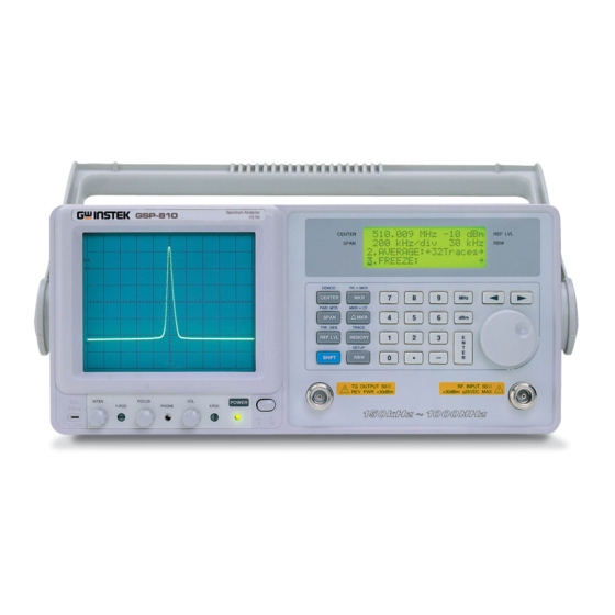
GSP-810 User Manual 3.0 Panel Descriptions Front Panel GlobalTestSupply www. .com Find Quality Products Online at: sales@GlobalTestSupply.com... - Page 10 GSP-810 User Manual Item Description Cathode Ray Tube (CRT) Display, 8 x 10 graticule, 5 inch Liquid Crystal Display (LCD), 4 line x 20 character Keypad, field selection and data entry Spinner, field selection and data change RF Input, Coaxial, Type N Female...
- Page 11 GSP-810 User Manual Rear Panel GlobalTestSupply www. .com Find Quality Products Online at: sales@GlobalTestSupply.com...
- Page 12 GSP-810 User Manual Item Description Panel Label, Usage Warning External Frequency Reference Input, BNC (optional) Connector, DB9, Female, RS-232 Panel Label, Serial Number Cooling Fan Vent Adjustment, CRT Trace Rotation, potentiometer Adjustment, Internal Frequency Reference , potentiometer Adjustment, LCD Contrast, potentiometer...
-
Page 13: Setup And Use
For instance, pressing BLUE followed by MEMORY selects the TRACE functions. The following table contains a list of the various data fields that may be controlled within the GSP-810, the selection for the field and the means to change or enter data into the field. - Page 14 GSP-810 User Manual Field Selection Key Data Entry Resolution Bandwidth SPINNER to scroll (SPAN OF 0 Hz / div ONLY) Demodulation (Optional SPINNER to select demod type SHIFT , DEMOD Receiver) Power Meter (Optional) SPINNER selects change line; SHIFT , PWR MTR to select an item;...
- Page 15 GSP-810 User Manual CENTER FREQ This field is the value for the frequency located at the mid-point (center screen) of the selected span. This frequency value may be changed by entering the digits, decimal point, followed by the ENTER or MHz key, or the keys can select a digit to increment or decrement using the SPINNER.
- Page 16 GSP-810 User Manual SPAN This field is the value for the frequency range covered by the GSP-810 as it sweeps its receiver. This span value may be changed by the SPINNER to roll through the list of valid spans. The range of valid entries is 2 kHz / division through 100 MHz / division plus zero span (0 Hz / div).
- Page 17 GSP-810 User Manual REF LVL This field is the value (on the top of screen) for the received input signal. This reference level value may be changed by the rotating the SPINNER to scroll through the list of valid reference levels.
- Page 18 GSP-810 User Manual MARKERS The GSP-810 supports 2 markers. To access the marker screen, press the MRK key. Displayed will be 2 marker frequencies. Accessing the marker frequency fields is performed through the left column of numbers. Cursor to the left most position, then use the SPINNER to switch between marker 1 and marker 2.
- Page 19 SHIFT PK->MKR This is a peak search function. Using marker 1, the GSP-810 begins at the current marker 1 frequency and scans for a peak. When a peak is found in the trace, the marker frequency is updated to show the frequency of the signal and the level of the peak is also displayed.
- Page 20 GSP-810 User Manual DELTA MARKERS The delta marker function is similar to the marker function. To access the marker screen, press the ΔMKR key. In this function marker 1 is used as the reference marker level and the marker 2 level is level difference between marker 1 and marker 2.
- Page 21 TRACE The TRACE key provides access to the Peak Hold, Average, and Freeze features of the GSP-810. These items are shown on the bottom half of the LCD display. By scrolling, all three items can be accessed. The Max Hold Function, when enabled, will maintain a trace showing the maximum signal received for each point in the trace.
- Page 22 Then use the SPINNER to change the number from 1 to 10. While the cursor is on that field, pressing the ENTER key will load the current state of the GSP-810 with the loaded parameters.
- Page 23 GSP-810 User Manual SETUP SCREEN The setup screen provides access to various parameters. The setup screen functions are accessed by pressing the SHIFT RBW key. The trace will stop updating while in the setup screen. The parameters are accessible using the SPINNER.
- Page 24 GSP-810 User Manual 5. LO2 Status This displays the status of LO2. An internal status is monitored to determine if it is “Locked” or “Unlocked” with the result being displayed. 6. LO3 Status This displays the status of LO3. An internal status is monitored to determine if it is “Locked”...
- Page 25 GSP-810 User Manual Operation Next figure shows a typical spectrum display. This example shows the settings for a 100 MHz center frequency, a 1 MHz / division span and a reference level of -10 dBm. The 8 by 10 division display indicates RF level on the vertical or y-axis, and frequency on the horizontal or x-axis.
- Page 26 GSP-810 User Manual DEMOD (Optional) The GSP-810 can be optionally configured to perform FM and AM demodulation. To access this feature, press the SHIFT DEMOD key. The bottom half of the LCD display will show the current demodulation selection that can be changed with the SPINNER.
- Page 27 To use the normalize function, connect the equipment to the tracking generator output port and the spectrum analyzer input port. Following a normalize, the GSP-810 will factor out the measured variances. When the Span or Center Frequency fields are changed, the normalize will be reset and should be run again.
- Page 28 GSP-810 User Manual POWER METER (Optional) To access the power meter in the GSP-810, press the SHIFT PWR MTR. The bottom half of the screen will show the power level in mW or dBm based on the units selected in the setup screen. The range field will allow the user to change the range of 2mW, 20mW, 200mW and 2W (or equivalently 3dBm, 13dBm, 23dBm and 33dBm).
-
Page 29: Quick Use Index
GSP-810 User Manual 5.0 Quick Use Index (1) Full Span : Set CENTER=500MHz, SPAN=100MHz/Div, REF LVL=20dBm. See CENTER FREQ, SPAN, REF LVL(P. 13~15). (2) Max. Hold : SHIFT + TRACE → 1.Max Hold. See TRACE (P. 19). (3) Average : SHIFT + TRACE → 2.Average. See TRACE (P. 19). -
Page 30: Specifications
GSP-810 User Manual 6.0 Specifications Specifications are subject to change without notice. Refer to Goodwill Instrument Co., LTD. for latest specifications. SPECIFICATIONS FREQUENCY Frequency Range 150kHz ~ 1GMHz ±10ppm, 0 ~ 50ºC, ±2ppm/yr Aging Rate Span Range Zero, 2kHz ~ 100MHz/div in 1-2-5 sequence... - Page 31 GSP-810 User Manual DISPLAY SYSTEM Display Device CRT Display, 8 x 10 graticule, 6-inch waveform screen LCD Display, 4 line x 20 character data screen Display Function Center Frequency Control, Bandwidth, Reference Level, Span Range, Amplitude FUNCTIONS Marker Mode Absolute, relative, PK->marker, marker->center...
- Page 32 GSP-810 User Manual OPDERING INFORMATION GSP-810 1GHz Spectrum Analyzer ACCESSORIES : User manual x 1, Power cord x 1 OPTION Opt. 01 TRACKING GENERATOR (Factory Installed) Frequency Range 150kHz ~ 1GHz Amplitude Range -50dBm ~ 0dBm Amplitude Resolution ±1dB @ 0dBm, 80MHz Amplitude Accuracy ±1dB @ 50MHz...
- Page 33 GSP-810 User Manual OPTIONAL ACCESSORIES ATA-001 BNC Antenna (An additional ADP-001 is needed for fitting GSP spectrum analyzers) ATA-002 Near Fied Probe Wideband, 0.1 ~ 1000MHz, Low Noise, 2.9dB Typical RLB-001 Return Loss Bridge RLB Frequency Range 10MHz ~ 1GHz...
-
Page 34: Appendix 1 - Remote Operation (Standard And Option)
With remote operation, the GSP-810 is capable of communicating with a computer over the RS-232 port. No setup is required on the GSP-810 to enable the remote interface. The GSP-810 will monitor the RS-232 port and respond when a PC is connected. - Page 35 GSP-810 User Manual GSP810try To install GPS810try, download the GSP-810 Remote display software to get “GSP810try.zip” file. Extract the GSP810try.zip to execute “setup.exe”. It is easy to setup this application by following the prompt instructions. After the successful installation, there will be an icon of GSP810try added onto program files.
- Page 36 GSP-810 User Manual There are File, Setting, About and Help functions on the display area. File To quit this application, same as Quit in Control Panel. Setting To set the configuration of the display. About Information of this application program.
- Page 37 GSP-810 User Manual GSP810 To install GPS810, download the GSP-810 Remote control software to get “GSP810.zip” file. Extract the GSP810.zip to execute “setup.exe”. It is easy to setup this application by following the prompt instructions. After the successful installation, there will be an icon of GSP810 added onto program files.
- Page 38 GSP-810 User Manual Display Area Edit To edit the limit line. See “Limit” function in following. License To enter the license code. The others are the same as GSP810try. Control Panel There are four divisions of the control functions. They are Basic Function, Marker, Limit, TG Function, Trace Record and General Function.
- Page 39 GSP-810 User Manual TG Function All TG control functions can be remote control. The control is worked when the TG mode is in use. Clicking TG Mode/SA Mode can toggle the TG and SA control. Trace Record Trace Record offers the ability to store the dynamic trace in memory. It is very convenient to long term recording for tracking the sudden interference or signal.
- Page 40 GSP-810 User Manual RS-232 (9 Pin Female) Some DTE devices may have female connectors. Also, the RS-232 parts of personal computers may be configured as DCE or DTE devices, with either a 25-pin or a 9-pin connector. Refer to the documentation that accompanies your computer or terminal to determine if it is a DTE or a DCE device.
Need help?
Do you have a question about the GSP-810 and is the answer not in the manual?
Questions and answers