
Subscribe to Our Youtube Channel
Related Manuals for GW Instek LCR-8000G Series


Summary of Contents for GW Instek LCR-8000G Series
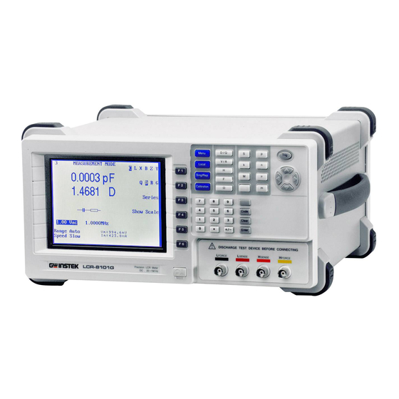
- Page 1 Precision LCR Meter LCR-8000G Series USER MANUAL GW INSTEK PART NO. 82CR-81010MB1 ISO-9001 CERTIFIED MANUFACTURER...
- Page 2 This manual contains proprietary information, which is protected by copyright. All rights are reserved. No part of this manual may be photocopied, reproduced or translated to another language without prior written consent of Good Will company. The information in this manual was correct at the time of printing. However, Good Will continues to improve products and reserves the right to change specification, equipment, and maintenance procedures at any time without notice.
-
Page 3: Table Of Contents
TABLE OF CONTENTS Table of Contents SAFETY INSTRUCTION ............ 5 GETTING STARTED ............10 Main Features ........12 Package Contents......... 13 Measurement Type....... 13 Model Comparison ......15 Front Panel Overview ......16 Rear Panel Overview ......19 Tilt Stand & Power Up ......21 Fixture Connection....... - Page 4 LCR-8000G Series User Manual Speed / Step Setting ......101 Running Graph Measurement .... 103 REMOTE CONTROL ............107 Interface Configuration ...... 108 Command Syntax ....... 111 Command Set ........112 CALIBRATION............... 123 FAQ................128 APPENDIX ..............129 Fuse Replacement ......129 ...
-
Page 5: Safety Instruction
TABLE OF CONTENTS AFETY INSTRUCTION This chapter contains important safety instructions that you must follow when operating or storing an LCR-8000G series LCR meter. Following these instructions will ensure your safety and keep the instrument in the best possible condition. - Page 6 LCR-8000G Series User Manual Do not dispose electronic equipment as unsorted municipal waste. Please use a separate collection facility or contact the supplier from which this instrument was purchased. Safety Guidelines Do not place any heavy object on the General •...
- Page 7 SAFETY INSTRUCTION Fuse type: T3A/250V Fuse • Make sure the correct type of fuse is installed • before power up. WARNING To ensure fire protection, replace the fuse only • with the specified type and rating. Disconnect the power cord before fuse •...
- Page 8 LCR-8000G Series User Manual (Pollution Degree) EN 61010-1:2001 specifies the pollution degrees and their requirements as follows. The LCR-8000G falls under degree 2. Pollution refers to “addition of foreign matter, solid, liquid, or gaseous (ionized gases), that may produce a reduction of dielectric strength or surface resistivity”.
- Page 9 SAFETY INSTRUCTION Power cord for the United Kingdom When using an LCR-8000G series LCR meter in the United Kingdom, make sure the power cord meets the following safety instructions. NOTE: This lead/appliance must only be wired by competent persons WARNING: THIS APPLIANCE MUST BE EARTHED...
- Page 10 LCR-8000G Series User Manual ETTING STARTED This chapter describes the LCR-8000G series in a nutshell, including their main features, model comparison, front / rear panel appearance, and power up sequence. Use the Tutorial section for a quick access to the main functionalities, step by step.
-
Page 11: Getting Started
GETTING STARTED Fixture Fixture structure .............24 connection Fixture connection............25 Tutorial Basic measurement (without Pass/Fail test) ....26 Pass/Fail test (Single step) ...........28 Pass/Fail test (Multiple step) ........30 Graph mode..............32 Measurement tip Measurement tip ..........34... -
Page 12: Main Features
LCR-8000G Series User Manual Main Features 20Hz ~ 10MHz wide test frequency (LCR- Performance • 8110G) 6 digit measurement resolution • 10mV ~ 2V measurement drive level • (DC/20Hz~3MHz) 0.1% basic measurement accuracy • Spot frequency measurement Operation • Multi-step measurement, maximum 64 •... -
Page 13: Package Contents
Package Contents Ensure all the package contents are included and defect-free before using the LCR-8000G. If any of the contents in your package are missing or damaged, please contact your nearest GW Instek distributor. LCR 8000G model LCR User manual Standard •... -
Page 14: Item Measurement Combination
LCR-8000G Series User Manual Measurement combination :Available, :Not available, :Combination doesn’t exist. 1st measurement 2nd measurement Circuit model Graph *Prog G Angle Series Parallel Capacitance (C) Inductance (L) Reactance (X) Susceptance (B) Impedance (Z) Admittance (Y) DC Resistance(R Quality factor (Q) -
Page 15: Model Comparison
GETTING STARTED Model Comparison Major Model Differences LCR-8101G LCR-8105G LCR-8110G Model 20Hz~1MHz 20Hz~5MHz 20Hz~10MHz Measurement Frequency 20Hz~1MHz: 20Hz~≤3MHz: 20Hz~≤3MHz: Drive Signal Level 0.01V~2Vrms 0.01V~2Vrms 0.01V~2Vrms >3MHz~5MHz: >3MHz~10MHz: 0.01V~1Vrms 0.01V~1Vrms 0.01V~2V 20Hz~1MHz: 20Hz~≤3MHz: 20Hz~≤3MHz: Drive Signal Short 100uA~20mA 100uA~20mA 100uA~20mA Circuit Current >3MHz~5MHz: >3MHz~10MHz: 100uA~10mA... -
Page 16: Front Panel Overview
LCR-8000G Series User Manual Front Panel Overview Single/ Main Function Local Menu Calibration Unit Trigger Repetitive Display Keys Keys Arrow Keys D / Q Menu Trig V / A Local Code ∝ Clear Code Clear Enter Enter DISCHARGE TEST DEVICE BEFORE CONNECTING... - Page 17 GETTING STARTED Enters the calibration mode. See Calibration key Calibration page123 for calibration details. Enters unit when editing values. Unit keys Dissipation factor or Quality factor Voltage or Ampere Henry (for Inductance) Farad (for Capacitance) Ohm (for Resistance, Impedance) Ω Siemens (for Susceptance, Admittance) Kilo (10...
- Page 18 LCR-8000G Series User Manual Confirms the entered value or Enter key Enter selection. Enters numeric values. Numerical keys Accepts measurement fixture. For connection Measurement details, see page24. terminals Current return LFORCE Low potential LSENSE High potential HSENSE Current output HFORCE...
-
Page 19: Rear Panel Overview
GETTING STARTED Rear Panel Overview Display Contrast GPIB RS-232C Voltage Fuse Mains Knob Port Port Selector Holder Socket RS232 GPIB AC 115 / 230V 50 / 60Hz FUSE 250V T 3A WARNING SER.NO. LABEL GPIB Accepts remote control cables. GPIB port / RS-232C port RS232 GPIB: 24-pin female... - Page 20 LCR-8000G Series User Manual The voltage selector sets the AC Voltage selector / Fuse holder / mains voltage: Mains socket AC 115V (+10% / -25%), AC 230V (+15% / -14%) (Selectable), 50/60Hz. The fuse holder contains the main fuse, T3A/250V. For fuse replacement details, see page129.
-
Page 21: Tilt Stand & Power Up
GETTING STARTED Tilt Stand & Power Up Tilt stand Low angle High angle... -
Page 22: Up Power Up
LCR-8000G Series User Manual Power up 1. Set the rear panel 230V 115V Voltage selector to the correct position Panel operation according to the AC mains voltage. 2. Connect the power cord to the socket. 3. Turn On the power switch. -
Page 23: Select Ac Mains Frequency (50/60Hz)
GETTING STARTED Select AC mains frequency (50/60Hz) Although the LCR-8000G works under both 50 and Background 60Hz power frequencies, we recommend selecting the frequency that matches the local setting to get the best measurement precision, especially at lower frequencies (< 100Hz). 1. -
Page 24: Fixture Connection
LCR-8000G Series User Manual Fixture Connection Fixture structure The standard fixture is a four-wire type with a Background common terminal for screen connection. The outer terminals (Hforce and Lforce) provide the current and the inner terminals (Hsense and Lsense) measures the potential. -
Page 25: Connection Fixture Connection
GETTING STARTED Fixture connection 1. Discharge the test component before Panel operation connecting the fixture set. 2. Connect each fixture terminal to the front panel BNC connector with matching color. FORCE SENSE SENSE FORCE 3. Connect the fixture to the test component. If the component has polarity, connect the H side to the positive lead and the L side to the negative lead. -
Page 26: Tutorials (Step By Step Operations)
LCR-8000G Series User Manual Tutorials (Step by Step Operations) Basic measurement (without Pass/Fail test) Step Description Details 1. Connect fixture Connect the fixture to the DUT. Page24 Press the Menu key, followed by F1 (AC Page47 2. Enter menu measurement) or F2 (Rdc). - Page 27 GETTING STARTED Optional settings To hide the drive Voltage/Current, press Page57 the Code key, type 80, then press Enter. Page51 Set the Range (internal setting) to Auto, use the Left/Right key to move the cursor and Up/Down key to change the setting.
-
Page 28: Pass/Fail Test (Single Step)
LCR-8000G Series User Manual Pass/Fail test (Single step) Step Description Details 1. Connect fixture Connect the fixture to the DUT. Page24 Press the Menu key, then F5 (System). Page61 2. Set buzzer sound Press the Up/Down arrow key to move... - Page 29 GETTING STARTED Press the Sing/Rep key to select Page56 10b. Select Repetitive Repetitive (automatic trigger) measurement measurement. Press the Left/Right arrow key and move the cursor to Speed. Press the Up/Down key to select the speed. Press F5 (Abs/%/∆) to select Abs. Press Page66 11a.
-
Page 30: Pass/Fail Test (Multiple Step)
LCR-8000G Series User Manual Pass/Fail test (Multiple step) Step Description Details 1. Connect fixture Connect the fixture to the DUT. Page24 Press the Menu key, then F5 (System). Page72 2. Set buzzer sound Press the Up/Down arrow key to move... - Page 31 GETTING STARTED Press F6 (Run). The Run menu opens. Page80 8. Enter Run menu Press the Sing/Rep key to select Single Page80 9. Set Single or (manual trigger) or Repetitive (auto Repetitive trigger). 10. Start running If the test has not started yet, press F1 Page80 (Start) or Trig key.
-
Page 32: Graph Mode
LCR-8000G Series User Manual Graph mode Step Description Details 1. Connect fixture Connect the fixture to the DUT. Page24 Press the Menu key, then F4 (Graph). Page88 2. Enter graph mode Press F5 repeatedly to select the graph Page89 3. Select item item. - Page 33 GETTING STARTED Press F2 (Abs/%) to select Abs, then press Page94 8b. Set vertical scale (Absolute + F3 (Manual/Auto fit) to select Manual fit. Manual fit) Move the cursor to Hi, set the Hi value. Repeat this for Lo as well. The minimum and maximum vertical range is manually configured.
-
Page 34: Measurement Tip
LCR-8000G Series User Manual Measurement tip If the measured impedance is greater than 1kΩ, Hi/Low impedance the standard four-terminal connection is not necessary. Run S/C trim to remove the effect of series lead impedance. If the measured impedance is lower than 1kΩ, four-terminal connection can reduce the effect of contact resistance at the test component. - Page 35 GETTING STARTED Wire capacitance When measuring the wire capacitance, the fixture clips that are marked with H (High Force)/H (High Sense) should always be connected to the point that is influenced the most by noise. The wire inductance should be subtracted from Wire inductance the measurement result.
-
Page 36: Basic Measurement
LCR-8000G Series User Manual ASIC MEASUREMENT Basic measurement measures DUT in numerical style. Advanced measurements are available in Pass/Fail test mode (page58), where measurement results are compared with user-defined limits, and in Graph mode (page87), where measurement data is displayed in graphical representation. -
Page 37: Measurement Item Description
BASIC MEASUREMENT Measurement Item Description In general, two items, primary and secondary, are combined in a single measurement. The following table shows the available combinations. Overview of each measurement item is listed from the next page. Measurement combination :Available, :Not available, :Combination doesn’t exist. -
Page 38: Item Series/Parallel Circuit Models
LCR-8000G Series User Manual Series/Parallel circuit models For measuring AC Resistance, Capacitance, Background Reactance, Inductance, and Susceptance, series and parallel equivalent circuit models are available. Select the model according to the component value. Capacitance (C) Series diagram Parallel diagram Series formula... - Page 39 BASIC MEASUREMENT Series formula Parallel formula ⎛ ⎞ ⎜ ⎜ ⎟ ⎟ ⎛ ⎞ ⎝ ⎠ ⎜ ⎜ ⎟ ⎟ ⎝ ⎠ Q=quality factor Q=quality factor When to use Series (L When to use Parallel (L Small capacitance: Large capacitance: Reactance (X ) <...
-
Page 40: Resistance (R) And Conductance (G = 1/R)
LCR-8000G Series User Manual Resistance (R) and Conductance (G = 1/R) Resistance measures how difficult it is for the Background electricity to flow between two terminals. Conductance is the reciprocal of Resistance and measures how easily the electricity flows. Resistance... -
Page 41: Capacitance (C)
BASIC MEASUREMENT Capacitance (C) Capacitance measures the amount of electronic Background charge stored between two terminals. 0.001pF ~ 1F Display Range Parallel Capacitance C Series Capacitance C Type • • Combination • • • • • • • ϖ Formula −... -
Page 42: Inductance (L)
LCR-8000G Series User Manual Inductance (L) Inductance measures the amount of magnetic flux Background generated in certain electrical current. 0.1nH ~ 100kH Display Range Series Inductance L Parallel Inductance L Type • • Measurement • • combination • • •... -
Page 43: Reactance (X) And Susceptance (B = 1/X)
BASIC MEASUREMENT Reactance (X) and Susceptance (B = 1/X) Reactance measures the imaginary part of Background Impedance (Z) caused by capacitors or inductors. Susceptance is the reciprocal of Reactance and measures the imaginary part of Admittance (Y), which is also the reciprocal of Impedance. Series Reactance (X Parallel Susceptance (B Type... -
Page 44: Impedance (Z) And Admittance (Y = 1/Z)
LCR-8000G Series User Manual Impedance (Z) and Admittance (Y = 1/Z) Impedance measures the total amount of Background opposition between two terminals in an AC circuit. Admittance is the reciprocal of Impedance and measures how easily the electricity flows in an AC circuit. -
Page 45: Quality Factor (Q) And Dissipation Factor (D)
BASIC MEASUREMENT Quality factor (Q) and Dissipation factor (D) Both Quality factor and its reciprocal, Dissipation Background factor, are used for measuring the rate of energy dissipation relative to the measurement frequency. Low energy dissipation: high Q, low D • High energy dissipation: low Q, high D •... -
Page 46: Angle (Θ)
LCR-8000G Series User Manual Angle (θ) The Angle (θ) measures the phase on which Background Impedance (Z), Admittance (Y), Quality factor (Q), and Dissipation factor (D) are measured. Angle (θ) Type –180° ~ +180° Display Range Formula ϖ ϖ −... -
Page 47: Measurement Mode Overview
BASIC MEASUREMENT Measurement Mode Overview Enter measurement mode C, L, X, B, Z, Y, Q, D, R, G, θ Type Menu 1. Press the Menu key. The main menu Panel operation appears. MAIN MENU AC MEAS Rdc MEAS MULTI STEP GRAPH SYSTEM 2. -
Page 48: Overview Display Overview
LCR-8000G Series User Manual Display overview Normal mode Absolute mode (Pass/Fail test) Percentage mode (Pass/Fail test) -
Page 49: Show Circuit Model Or Scale (Pass/Fail)
BASIC MEASUREMENT Delta mode (Pass/Fail test) For Pass/Fail test details, see page58. Show circuit model or scale (pass/fail) The center of the display can be filled with the Background diagram of equivalent circuit model, or the measurement scale with Pass/Fail test result. This selects not only the diagram/scale but also whether running the Pass/Fail test or just measuring the value. -
Page 50: Parameter Configuration
LCR-8000G Series User Manual Parameter Configuration Select measurement item *This is not necessary for Rdc measurement. The following list shows the available combination Measurement combination of the first and second measurement items. Capacitance (C) Series C-Q, C-D, C-R Parallel C-Q, C-D, C-R, C-G... -
Page 51: Configuration Set Measurement Range To Auto
BASIC MEASUREMENT Set measurement range to Auto The measurement range is an internal parameter Background defining the search range for each measurement item. Make sure the Auto setting is always selected, to obtain the best measurement accuracy. The active range appears at the top left corner of the display. -
Page 52: Set Measurement Frequency
LCR-8000G Series User Manual Set measurement frequency *This setting does not apply to Rdc measurement. The measurement frequency, together with the Background measurement voltage, defines the electrical condition of each measurement item. Make sure the appropriate frequency is selected, according to the component characteristics. - Page 53 BASIC MEASUREMENT For frequency increase/decrease using Up/Down Select frequency keys, fine and coarse step settings are available. step resolution Fine digit: 1, 2, 3, 4, 5, 6... Coarse digit: 10, 12, 15, 20, 25, 30, 40, 50, 60, 80 1. Press the Code key. Code 2.
-
Page 54: Set Measurement Voltage
LCR-8000G Series User Manual Set measurement voltage The measurement voltage, together with the Background measurement frequency, defines the electrical condition of each measurement item. Make sure the appropriate voltage is selected, according to the component characteristics. 1. Press the Left/Right key repeatedly Voltage setting to move the cursor to Voltage. -
Page 55: Running Measurement
BASIC MEASUREMENT Running Measurement Select Single measurement The data capture can be manually controlled Background (Single) or automatically updated (Repetitive). In single measurement, the measurement is activated by pressing the Trigger key. In repetitive measurement, the measurement is automatically done and the display is updated according to the speed (timing) setting. -
Page 56: Select Repetitive Measurement
LCR-8000G Series User Manual Select Repetitive measurement The data capture can be manually controlled Background (Single) or automatically updated (Repetitive). In single measurement, the measurement is activated by pressing the Trigger key. In repetitive measurement, the measurement is automatically done and the display is updated according to the speed (timing) setting. -
Page 57: Hide Drive Voltage/Current
BASIC MEASUREMENT AC≤ AC≤ AC> AC≥ 100Hz 2kHz 2kHz 1MHz 900ms 1.3s 600ms 600ms 620ms Slow 120ms 1.2s 470ms 450ms 470ms 60ms 650ms 180ms 150ms 150ms Fast 30ms 600ms 120ms 75ms 120ms If the beep setting (page61) is active and Beep setting Sing/Rep the display is in Pass/Fail test mode, it... -
Page 58: Pass-Fail Mode
LCR-8000G Series User Manual ASS-FAIL MODE In the Pass/Fail test mode, measurement results are compared with user-defined limits and the results are displayed. Two types of tests are available: Single and Multi-Step. The Single test shares the same interface with the basic measurement, and tracks one item. - Page 59 PASS-FAIL MODE Multi-step run Run program ............80 Multi-step file Save program ............. 83 operation Recall (load) existing program ......85 Delete existing program ........86...
-
Page 60: Single-Step Test Configuration
LCR-8000G Series User Manual Single-Step Test Configuration Overview Pass/Fail test checks whether the measurement Background / test result sits between the Hi(high) and Lo(low) limit. type Three methods are available: absolute limit, percentage and delta limit. The Hi and Lo limit are defined by Absolute absolute values. -
Page 61: Configure Beep Setting
PASS-FAIL MODE Parallel resistance θ Angle For detailed description of each item, see page37. Configure beep setting The beep sounds when the pass/fail test result Background matches the setting: failed or passed. 1. Press the Menu key, then F5 Panel operation Menu (System). -
Page 62: Configure The Average
LCR-8000G Series User Manual If the repetitive measurement is On, the beep Beep in repetitive might sound continuously. If this becomes a mode problem, either use the Single mode (press Sing/Rep key) or turn Off the beep. Configure the Average... -
Page 63: Select Test Item And Scale (Pass/Fail Test)
PASS-FAIL MODE Select test item and scale (Pass/Fail test) To select the first measurement item, Test item press F1 repeatedly. L X B Z Y To select the second measurement item, press F2 repeatedly. D R G To select the circuit model, series or Circuit model parallel, press F3 repeatedly. -
Page 64: Set Parameters
LCR-8000G Series User Manual Set parameters For more detailed descriptions, see Basic measurement, page47. How to edit Example Enter 100mV Backspace All clear Clear Increase Decrease When the entered value does not fit in the range, the nearest available value is selected. - Page 65 PASS-FAIL MODE Press the Left/Right key repeatedly to Frequency (except move the cursor to Frequency, and use Rdc) the numerical and unit keys to enter the value. 2.00 195.00 kHz For frequency increase/decrease using Up/Down Frequency step resolution keys, fine and coarse step settings are available. Press the Code key and enter 10 (Fine) Code or 11 (Coarse).
-
Page 66: Single-Step Test Run
LCR-8000G Series User Manual Single-Step Test Run Run in Absolute mode 1. Press F5 to select Absolute measurement. 2. Use the Left/Right key to move the cursor to Hi/Lo value for editing. 0.00mF 20.0mF 3. Use the numerical keys Range... -
Page 67: Run In Percentage Mode
PASS-FAIL MODE Result > Hi Result < Lo Lo < Result < Hi PASS (Pass) Run in Percentage mode 1. Press F5 to select Percentage measurement. 2. Use the Left/Right key to move the cursor to Hi/Lo value for editing. +1.00% 100.00mD –1.00%... -
Page 68: Run In Delta Mode
LCR-8000G Series User Manual Hi and Lo values are automatically swapped if necessary Hi and Lo Swapped 4. The display updates the Hi/Lo result immediately. The result is pass if the bar stays in the central area. The buzzer sounds accordingly. -
Page 69: Use Display Value As Nominal
PASS-FAIL MODE Backspace All clear Clear Hi and Lo values are automatically swapped if necessary Hi and Lo Swapped 4. The display updates the Hi/Lo result immediately. The result is pass if the bar stays in the central area. The buzzer sounds accordingly. -
Page 70: Multi-Step Test Configuration
LCR-8000G Series User Manual Multi-Step Test Configuration Overview The multi-step function can configure and run Background multiple measurement steps. Maximum 64 programs, 30 steps each, can be programmed and stored in the instrument. Only the absolute limit Limit type testing is available. For percentage limit test, use the single mode (page60). - Page 71 PASS-FAIL MODE Maximum 30 for each program Parameters No. of step No. of program Maximum 64 10mV ~ 2V (DC or AC≤3 MHz) Drive Voltage 10mV ~ 1V (AC>3 MHz) (1mV step) 20Hz ~ 1MHz (LCR-8101G) Frequency 20Hz ~ 5MHz (LCR-8105G) 20Hz ~ 10MHz (LCR-8110G) Reserved item: internal use only Bias...
-
Page 72: Configure Beep Setting
LCR-8000G Series User Manual Configure beep setting The beep sounds when the pass/fail test result Background matches the setting: failed or passed. 1. Press the Menu key, then F5 Panel operation Menu (System). The system configuration appears. Precision LCR Meter LCR-8101 Software version 2.03 Oct 25 2008... -
Page 73: Configure The Average
PASS-FAIL MODE Configure the Average The Average function sets the number of samples Background used, which are then averaged as the final output. The number of samples varies from 1 to 256. 1. Press the Menu key, then F5 Panel operation Menu (System). -
Page 74: Enter Multi-Step Mode
LCR-8000G Series User Manual Enter multi-step mode Press the Menu key, then F3 (Multi Panel operation Menu Step). The multi-step mode menu appears. The last recalled program appears on the display. Create new program 1. In the multi-step mode, press F5 Panel operation (File), then F4 (New). - Page 75 PASS-FAIL MODE 2. Enter the new program name using the arrow keys. Move cursor JKLMNOPQRS (Left/Right keys) Enter the letter program name: N_ (Down key) Delete one letter program name: _ (Up key) 3. Press the Enter key to confirm the Enter file name.
-
Page 76: Edit Program Step
LCR-8000G Series User Manual Edit program step For selecting parameters, press F1 How to edit • (Prog) repeatedly. parameter For entering values, use the numerical and unit • keys. Example: Enter 0.5kHz Backspace All clear Clear Increase Decrease To move the cursor to the editing point,... - Page 77 PASS-FAIL MODE Move the cursor to Freq column. Set frequency Func Enter the frequency using the Freq 500.00 numerical keys and unit keys. Volt 2.00 V 20Hz ~ 1MHz/5MHz/10MHz Range 5 digit resolution Example: Enter 0.5kHz (500Hz) Move the cursor to Volt column. Set voltage Freq 500.00...
- Page 78 LCR-8000G Series User Manual Move the cursor to Hi column. Set Hi limit Enter the Hi limit using the 1.0000H numerical keys and unit keys. 0.0000H follows the specification for each Range measurement item Example: 1.5kH (for Ls) Enter Move the cursor to Lo column.
-
Page 79: Copy (Duplicate) Program Step
PASS-FAIL MODE Copy (duplicate) program step Copying the step inserts a new, identical step next Background to the current step (= the step where the cursor resides). Press F2 (Copy). A new step with Panel operation identical contents appears on the right side. -
Page 80: Multi-Step Program Run
LCR-8000G Series User Manual Multi-Step Program Run Run program 1. When editing is completed, press F6 Panel operation (Run) to run the multi-step program. The display changes to program running mode. – MULTI STEP MODE Start PROGRAM: Demo 2. Press the Sing/Rep key to select... - Page 81 PASS-FAIL MODE 3. In Manual (single) mode press F1 Trig (Start) or the Trigger key to manually start the program. The test results show up according to the program contents. Manual (single) Mode 4. In Auto trigger mode, it will Trig autoscan continuously and will not start until a DUT has been detected.
- Page 82 LCR-8000G Series User Manual The rightmost row shows the result for each step. Failed: below the Lo limit Failed: above the Hi limit Passed The left bottom corner shows the result for the whole program. All steps passed PASS One or more steps failed FAIL 5.
-
Page 83: Multi-Step Program File Operation
PASS-FAIL MODE Multi-Step Program File Operation Save program Press F4 (Save) to save the program Save (overwrite) being edited. A confirmation message appears on the display. Program saved 1. Press F5 (File), then F3 (Save As). Save as (new program) The new program name dialogue appears. - Page 84 LCR-8000G Series User Manual 3. Press the Enter key to confirm the Enter file name. To quit the Save as mode, press the Clear key. Clear 4. The display goes back to the previous mode, with the program changed to the new name.
- Page 85 PASS-FAIL MODE Recall (load) existing program 1. Press F5 (File). The file menu Panel operation appears. 2. Press F1 (Load). The existing programs appear, listed in alphabetical order. 3. Use the arrow key to move the cursor to the program to be recalled (loaded).
- Page 86 LCR-8000G Series User Manual Delete existing program 1. Press F5 (File), then F2 (Delete). The Recall program existing programs appear, listed in alphabetical order. 2. Use the arrow key to move the cursor to the program to be deleted. 3. Press F5 (Del). The buzzer beeps and a warning sign appear.
-
Page 87: Graph Mode
GRAPH MODE RAPH MODE The graph function shows the component characteristics in visual manner. Voltage and Frequency sweep are selectable for the horizontal scale. When the graph gets out of the vertical range, the LCR-8000G can automatically adjust the scale. Marker operation is available for detailed observation. -
Page 88: Item Selection
LCR-8000G Series User Manual Item Selection Enter graph mode 1. Press the Menu key. The main menu Panel operation Menu appears. MAIN MENU AC MEAS Rdc MEAS MULTI STEP GRAPH SYSTEM 2. Press F4 (Graph). The Graph mode display appears. -
Page 89: Select Measurement Item
GRAPH MODE Select measurement item θ Series inductance Angle Range Parallel inductance Rs Series resistance Quality factor Parallel resistance Series capacitance Reactance Parallel capacitance G Conductance Dissipation factor Susceptance Impedance Admittance For detailed description of each item, see page37. Press F5 repeatedly to select the graph Panel operation measurement item. -
Page 90: Horizontal Scale Setting
LCR-8000G Series User Manual Horizontal Scale Setting Set horizontal axis (Voltage) The X (horizontal) axis is selectable from Voltage Background and Frequency sweep. When Voltage sweep is selected: measurement • Frequency is fixed When Frequency sweep is selected: • measurement Voltage is fixed 1. - Page 91 GRAPH MODE Unit Mismatched If a value outside of the range is entered, the closest available value is automatically selected. Nearest Available If the entered start Voltage level is higher than the stop Voltage, the two values are swapped. Hi and Lo Swapped 4.
-
Page 92: Set Horizontal Axis (Frequency)
LCR-8000G Series User Manual Set horizontal axis (Frequency) The X (horizontal) axis is selectable from Voltage Background and Frequency sweep. When Voltage sweep is selected: measurement • Frequency is fixed When Frequency sweep is selected: • measurement Voltage is fixed Select Frequency 1. - Page 93 GRAPH MODE Unit Mismatched If a value outside of the range is entered, the closest available value is automatically selected. Nearest Available If the entered start Frequency is higher than the stop Frequency, the two values are swapped. Hi and Lo Swapped 4.
-
Page 94: Vertical Scale Setting
LCR-8000G Series User Manual Vertical Scale Setting Set vertical axis (Manual + Absolute) The Y (vertical) axis configuration is available for: Background Manual or Automatic fit: Selects whether the • vertical range is manually set or automatically adjusted as the graph is plotted. - Page 95 GRAPH MODE 1.5kH Enter Backspace All clear Clear If a wrong unit is entered, the value is cancelled. Unit Mismatched If a value outside of the range is entered, the closest available value is automatically selected. Nearest Available If the entered Lo level is higher than the Hi level, the two values are swapped.
-
Page 96: Setting Set Vertical Axis (Manual + Percentage)
LCR-8000G Series User Manual Set vertical axis (Manual + Percentage) The Y (vertical) axis configuration is available for: Background Manual or Automatic fit: Selects whether the • vertical range is manually set or automatically adjusted as the graph is plotted. - Page 97 GRAPH MODE Backspace All clear Clear If a wrong unit is entered, the value is cancelled. Unit Mismatched If the entered Hi level is lower than the Lo level, the two values are swapped. Hi and Lo Swapped 6. Press the Up/Down key to move the Set Lo level cursor to Lo percentage and repeat the same step.
-
Page 98: Set Vertical Axis (Auto + Absolute)
LCR-8000G Series User Manual If a value outside of the range is entered, the closest available value is automatically selected. Nearest Available Set vertical axis (Auto + Absolute) The Y (vertical) axis configuration is available for: Background Manual or Automatic fit: Selects whether the •... -
Page 99: Set Vertical Axis (Auto + Percentage)
GRAPH MODE Set vertical axis (Auto + Percentage) The Y (vertical) axis configuration is available for: Background Manual or Automatic fit: Selects whether the • vertical range is manually set or automatically adjusted as the graph is plotted. Absolute or Percentage: Selects how the vertical •... - Page 100 LCR-8000G Series User Manual Backspace All clear Clear If a wrong unit is entered, the value is cancelled. Unit Mismatched If a value outside of the range is entered, the closest available value is automatically selected. Nearest Available 6. The LCR-8000G automatically configures the percentage (below and above the nominal level) of the vertical scale.
-
Page 101: Speed / Step Setting
GRAPH MODE Speed / Step Setting Select measurement speed (capture timing) The speed is the same setting used in the basic Background measurement (page56), except in the graph mode, maximum speed setting is not available. 1. Press the Up/Down key and move Panel operation the cursor to Speed. - Page 102 LCR-8000G Series User Manual Select step size The step size selects whether to plot every Background captured data (step size 1) or to plot only the selected data (step size 2, 4, 8 = every 2, 4, 8 data). Step size 1: detailed graph, slow capturing Step size 2, 4, 8: simplified graph, fast capturing 1.
-
Page 103: Running Graph Measurement
GRAPH MODE Running Graph Measurement Run measurement 1. When the configuration is Panel operation completed, press F4 (Start) to start the graph measurement. 2. The display changes into graph mode and starts plotting the measurement data. Measurement Ongoing CAPACITANCE VS FREQUENCY 300.0n 250.0n (Hz) - Page 104 LCR-8000G Series User Manual Marker CAPACITANCE VS FREQUENCY FUNCTION 300.0n 250.0n (Hz) 20.0 40.0 60.0 80.0 MKR: 32.000 Hz LEVEL: 10.0mV RETURN Cs : 250.00nF SPEED:FAST Marker position and Measurement data 5. To go back to the configuration mode, press F6 (Return).
-
Page 105: Adjust Vertical Scale
GRAPH MODE Adjust vertical scale When the measured data does not fit into the Background original vertical scale, use this function so that the LCR-8000G automatically adjusts the scale to include the whole plotted data. 1. If part or all of the plotted data are Panel operation out of the vertical range, use the automatic fit function. -
Page 106: Observe Graph Data
LCR-8000G Series User Manual Observe Graph Data When the graph is completed (page103) and the Background vertical scale is adjusted (page105), use the marker to observe the measurement data in detail. In the configuration mode, if the graph is already available, it can be viewed by pressing F6 (View). -
Page 107: Remote Control
REMOTE CONTROL EMOTE CONTROL This chapter describes basic aspects of IEEE488.2 based remote control. Both RS-232C and GPIB interface can be used for remote control. Interface Configure RS-232C interface ......108 Configuration Configure GPIB interface ........ 109 Command syntax Command Syntax ..........111 Command set System command ........... -
Page 108: Interface Configuration
LCR-8000G Series User Manual Interface Configuration Configure RS-232C interface DB-9, Male RS-232C Connector configuration 9600 Baud rate None Parity Data bit Stop bit RS232 Connect the RS-232C cable to the rear panel port: DB-9 male connector. 1 2 3 4 5... -
Page 109: Configure Gpib Interface
REMOTE CONTROL Configure GPIB interface Connect the GPIB cable to the Connection rear panel port: 24-pin female connector. Pin assignment Data line 1 Pin13 Data line 5 Pin1 Data line 2 Pin14 Data line 6 Pin2 Data line 3 Pin15 Data line 7 Pin3 Data line 4 Pin16 Data line 8... - Page 110 LCR-8000G Series User Manual 1. Press the Menu key and F5 (System). Select GPIB Menu address The system configuration appears. Precision LCR Meter LCR-8101 Software version 2.03 Oct 25 2008 Frequency 1MHz RS-232 Graph mode GPIB Line frequency 50Hz Beep...
-
Page 111: Command Syntax
REMOTE CONTROL Command Syntax IEEE488.2, 1992 (fully compatible) Compatible • standard SCPI, 1994 (partially compatible) • 1: command header Command format trig:del:mod <NR1>LF 2: single space 3: parameter 4: message terminator Parameter Type Description Example boolean logic 0, 1 <Boolean> integers 0, 1, 2, 3 <NR1>... -
Page 112: Command Set
Status Register as an integer in the range 0 to 255. It also clears ESR. Returns the LCR identification: Manufacturer, *idn? Model No, Serial No, Firmware version. Example: GW INSTEK, 8101, 0, 2.04 Sets the instrument to local state. *loc Sets the OPC bit of the ESR register. *opc... -
Page 113: Measurement Command
REMOTE CONTROL Returns the current contents of the Status Byte *stb? with the Master Summary bits as an integer in the range 0 to 255. Bit 6 represents Master Summary Status rather than Request Service. Triggers a direct measurement, but does not return *trg the results to the controller. - Page 114 LCR-8000G Series User Manual Returns the second AC function. :meas:func:minor Parameter: 0 (Q), 1 (D), 2 (R), 3 (G) If the first function is Z or Y, this command returns the last non-polar setting Sets or returns scale high limit as percentage.
-
Page 115: Multi-Step Program Command
REMOTE CONTROL Selects or returns measurement speed. :meas:speed <disc> Send parameter: max, fast, med, slow :meas:speed? Return parameter: 0 (max), 1 (fast), 2 (med), 3 (slow) Selects AC measurement. :meas:test:ac Selects Rdc measurement. :meas:test:rdc Returns measurement type. :meas:test? Parameter: 0 (AC measurement), 1 (Rdc measurement) Triggers an AC or Rdc measurement manually. - Page 116 LCR-8000G Series User Manual Sets or returns trigger delay time for currently :multi:delay <NR2> selected step in millisecond. :multi:delay? Parameter: 0ms ~ 1000ms Example: :multi:delay 10m (10ms) Sets or returns the frequency for the currently :multi:freq <NR2> selected step in Hz.
-
Page 117: Calibration Command
REMOTE CONTROL Create a new multi-step program. :multi:new <filename> Example: :multi:new demo (file name demo) Query the results of the test for each step. :multi:res? Parameter: 0 (Pass), 1 (Fail Hi), 2 (Fail Lo) Example: 1, +1.5E-7, 0, –0.2E-4 (step 1 failed on high limit, step 2 passed) Switches to the multi-step run page. -
Page 118: Graph Command
LCR-8000G Series User Manual Graph command Select graphing mode / path. :graph Set the measurement function for the graph mode. : graph:func Parameter: ls lp q cs cp d z phase rs rp x g b y rdc <disc> Example: :graph:func lp Returns the current measurement function of the graph mode. - Page 119 REMOTE CONTROL Returns the frequency if the sweep mode is drive :graph:freq? level Set the drive level if the sweep mode is frequency. Parameter: (.1 volts) .1v, 100m, 1e-1, 1.000000e-1 :graph:lev <NR3> Example: :graph:lev 100m • NOTE: e1 or e+1 is invalid for the lev command.
- Page 120 LCR-8000G Series User Manual Set the minimum value for Y-axis in the graph mode. Parameter: real number up to 1^12 (1e+12) :graph:lo-lim <NR3> Example: :graph:lo-lim -8.5e9 Note: The graph limits will only work whilst the “autofit” function is set to “off”...
- Page 121 REMOTE CONTROL Returns the measurement from the current marker position. Returned parameter: Depending on the measured :graph:mk? parameters. Example: (Series inductance) -3.510606e-03 (mH) Note: A graph must be plotted first. Move the marker to the frequency nearest the supplied value. :graph:mkf Parameter: (150 kHz) 150000, 150k, 1.5e5 <NR3>...
- Page 122 LCR-8000G Series User Manual Move the marker to the highest point on the current graph. :graph:peak Example: :graph:peak Move the marker to the lowest point on the current graph. :graph:dip Example: :graph:dip Print the current graph on an Epson compatible printer.
-
Page 123: Calibration
CALIBRATION ALIBRATION Overview Calibration (trimming) eliminates stray Background capacitance and series impedance from the testing fixture. It is required when using the instrument in a new environment, or using a new set of testing fixtures. The testing fixture clips are separated by a distance O/C trimming equal to the normal testing position. - Page 124 LCR-8000G Series User Manual Alternative S/C An alternative method of S/C trimming. trimming...
- Page 125 CALIBRATION Trim the LCR-8000G Prepare the fixture accordingly. (In order to run a Fixture setting complete trimming, both O/C and S/C trimming have to be done.) O/C trimming S/C trimming Alt. S/C trimming 1. Press the Calibration key. The Panel operation Calibration calibration mode menu appears.
- Page 126 LCR-8000G Series User Manual 2. Press F1 (O/C Trim) or F2 (S/C Trim) to select the trimming mode. 3. The trimming menu appears. S/C trimming SHORT THE TEST LEADS Spot freq SELECT A CHOICE <= 10kHz TO CONTINUE... <= 100kHz...
- Page 127 CALIBRATION ALL FREQUENCY SHORT CIRCUIT TRIM IN PROGRESS The display goes back to the Trim pass calibration mode menu. The Fail message appears on the Trim fail display. Press any other key to go back to the original menu. SHORT CIRCUIT TRIM FAILED Press any key to continue...
-
Page 128: Faq
LCR-8000G Series User Manual Q1. The beep keeps sounding. A1. The beep sounds according to the pass/fail test result, which in this case is set to repetitive mode. Do one of the following. Set the test mode to Single (manual trigger), so that the beep •... -
Page 129: Appendix
APPENDIX PPENDIX Fuse Replacement 1. Take off the power cord and remove the fuse Step socket using a minus driver. 6 0 H 5 0 / / 2 3 0 1 1 5 T 3 A 5 0 V F U S 2. -
Page 130: Z| Accuracy Chart
LCR-8000G Series User Manual |Z| Accuracy Chart Over the available frequency bands, the |Z| Accuracy Chart defines the measurement ranges available at specified accuracies. All curves assume that Slow measurement speed is used, that the analyzer has been trimmed at the frequency and level used for measurements, the factory calibration is valid and that the component under test is pure. -
Page 131: Z| Vs L, C Chart
APPENDIX |Z| vs L, C Chart... -
Page 132: Accuracy Definition
LCR-8000G Series User Manual Accuracy Definition |Z|, |Y| High Impedance Ae[%]=±((A+0.0000001*Zx)*Kv*Kt) Low Impedance Ae[%]=±((A+0.1/Zx)*Kv*Kt) L, C, X, B High Impedance when D < 0.1 Ae[%] = ± (( A + 0.0000001*Zx ) * Kv * Kt) High Impedance when D ≥ 0.1 Ae[%] = ±... -
Page 133: Specification
APPENDIX Specification Test Frequency LCR-8101G DC, AC:20Hz~1MHz LCR-8105G DC, AC:20Hz~5MHz LCR-8110G DC, AC:20Hz~10MHz Basic Accuracy R,Z,X,G,Y,B,L,C ±0.1%@1kHz R&G Accuracy When Qx≧0.1, multiply Ae by for R, G accuracies. Rac, Rdc, Rs, Rp, Z, Ls, Lp, D, G, B, θ, Cp, Cs, Q, Y, X Measurable Parameters Measurement... - Page 134 LCR-8000G Series User Manual Drive Signal Level LCR-8101G DC:0.01V~2V AC: 20Hz~1MHz: 0.01V~2Vrms LCR-8105G DC:0.01V~2V AC 20Hz~≤3MHz:0.01V~2Vrms AC >3MHz~5MHz:0.01V~1Vrms LCR-8110G DC:0.01V~2V AC 20Hz~≤3MHz:0.01V~2Vrms AC >3MHz~10MHz:0.01V~1Vrms Drive Signal Short LCR-8101G DC:100uA~20mA Circuit Current AC 20Hz~1MHz:100uA~20mA rms LCR-8105G DC:100uA~20mA AC:20Hz~≦3MHz:100uA~20mArms AC>3MHz~5MHz:100uA~10mA rms LCR-8110G DC:100uA~20mA AC:20Hz~≦3MHz:100uA~20mArms...
-
Page 135: Fixture Specifications
APPENDIX Operating Relative <80% Environment humidity Altitude <2000 meters Temperature 0°C~40°C Pollution Degree Storage Location Indoor Environment Relative <80% humidity Temperature -40°C~70°C Fixture Specifications LCR-09 LCR-12 LCR-13 Type SMD/chip test Kelvin clip test SMD/chip test fixture leads (4 Wire)+ fixture ground clip Frequency DC~10MHz... -
Page 136: Declaration Of Conformity
LCR-8000G Series User Manual Declaration of Conformity GOOD WILL INSTRUMENT CO., LTD. (1) No. 7-1, Jhongsing Rd., Tucheng City, Taipei County, Taiwan (2) No. 69, Lu San Road, Suzhou City (Xin Qu), Jiangsu Sheng, China declare, that the below mentioned product Type of Product: High Precision LCR Meter Model Number: LCR-8101G;... -
Page 137: Index
INDEX NDEX faq ......... 128 absolute mode ......66 overview ........ 48 accuracy dissipation factor specification ......133 accuracy definition ..... 132 admittance overview ........ 45 accuracy definition....132 drive signal overview.........44 specification ......134 angle overview ....... 46 drive voltage/current, hide .. 57 auto measurement range.. - Page 138 LCR-8000G Series User Manual configuration ......88 socket overview .....20 run......... 103 power up sequence....22 tutorial ........32 program, multi step ground symbol......5 copy step.........79 hide drive voltage/current ... 57 create new.......74 horizontal scale setting ..90 delete program.......86 delete step.......79...
- Page 139 INDEX step size setting, graph mode UK power cord ......9 ..........102 unit keys overview ....17 susceptance vertical scale setting ....94 accuracy definition....132 graph mode......105 overview.........43 voltage setting system command ....112 basic measurement ....54 test frequency graph mode......
Need help?
Do you have a question about the LCR-8000G Series and is the answer not in the manual?
Questions and answers