Table of Contents
Advertisement
Quick Links
Have this manual in the palm of
yout hand through the FG Finder
app.
1. DESCRIPTION
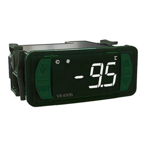
The VX-1005 is a digital temperature controller for refrigeration that has a digital output for actuating an
electronic expansion valve (EEV). In this way, it acts in superheating control in order to optimize the energy
efficiency of the controlled refrigeration system. It's a compact and integrated controller that offers a
complete solution for controlling electronic expansion valves. It has a dedicated control algorithm to run the
cooling process more efficiently without using the pressure transducer.
In addition to estimated superheat control, the instrument controls room temperature, defrosts, ventilation,
lighting and alarms. Room temperature control has an economical setpoint, in addition to fast-freezing
functionality. It adds the control of variable capacity compressors (VCC - Variable Capacity Compressor),
providing a series of benefits to the refrigeration system, such as: reduction of energy consumption, less
temperature oscillation, greater speed in reaching the desired temperature. By configuring its parameters,
it's possible to make the controller compatible with the main brands of variable compressors on the market.
For better use of energy, ventilation can be controlled during the off-cycle of the compressor and use Smooth
Defrost, a defrosting technique that reduces the final temperature of the electrical resistance and the amount
of heat emitted.
It has a serial communication output for integration with Sitrad, an internal real-time clock that allows
programming of defrost events, an intelligent function blocking system, a way to turn off control functions. In
addition, it has a digital filter functionality on the temperature sensor, which aims to simulate a mass increase
in the environment sensor (S1), thus increasing its response time (thermal inertia) and preventing
unnecessary compressor start-ups.
2. SAFETY RECOMMENDATIONS
- Make sure that the controller assembling is done property;
- Make sure that the power supply is turned off and not turned on during controller installation;
- Read this manual before installing and using the controller;
- Use appropriate Personal Protective Equipment (PPE);
- Install the vinyl adehesive protector (included) in installations prone to water splashes, such as refrigerated
counters, etc;
- Installation procedures must be performed only by licensed technicians, subject to codes and regulations.
3. APPLICATIONS
- Beverage displays and Display Cases.
4. TECHNICAL SPECIFICATIONS
Power supply
Average consumption
Temperature control range
Temperature resolution
Working temperature
Working Humidity
Digital input
Clock (RTC)
Frequency output
Degree of protection
Maximum Sizes
Bay Size
Output capacity
COMP
DEFR
FAN
AUX / LIGHT
5. DISPLAY AND KEYS
LED indicator Defrost cycle
LED indicator Fan enabled
LED indicator Compressor
Enabled
Flatec Key
Set Key
VX-1005
VX-1005
DIGITAL REFRIGERATION CONTROLLER WITH INTEGRATED
MODULE FOR AN ELECTRONIC EXPANSION VALVE
Electronic
Fast
Function
Switch off
Modbus
Expansion
Freezing
Lock
Control
Protocol
Functions
Valve
90 ~ 240Vca (50/60Hz)
-50 a 105°C / -58 a 221°F
0,1°C / 0,1°F
-20 a 60°C / -4 a 140°F
10 a 90% RH (without condensation)
Configurable dry contact type
Energy backup: CR1220 battery
Time keeping for up to 10 years
Accuracy: ±6 minutes/year
10Vcc
(± 10%)50mA max.
0...300Hz (duty-cycle = 50%)
IP 65 (front)
76 x 34 x 94mm / 2,99" x 1,33" x 3,70" (WxHxD)
X = 71
±0,5mm(2,79"±0,02") Y= 29±
0,5(1,14" 0,02")
(See Diagram 5)
120-240 Vac, 12 A Resistive, 100k cycles
120-240 Vac, 8 A General Use, 100k cycles
240 Vac, 1 HP, 100k cycles
120 Vac, 1/2 HP, 100k cycles
120-240 Vac, 5 A Resistive
240 Vac, 1/8 HP
120 Vac, 1/10 HP
240 Vac, 1/8 HP
120 Vac, 1/10 HP
120-240Vac 5W General Use
LED indicator for the auxiliary
outlet enabled
LED indicator for the EEV
LED indicator temperature unit
A
Up Key
Down Key
IP 65
VCC
FRONT
Programming
Monitoring
Degree
Quick coupling
Variable
in Series
System
of protection
connection
compressor
6. INSTALLATION - PANEL AND ELECTRICAL CONNECTIONS
71
± 0,5
mm
Size of the Bay for
inserting the device
Panel (Front View)
CAUTION
WHERE THE INSTALLATION LOCATION NEEDS TO BE SEALED AGAINST LIQUIDS, THE OPENING IN WHICH THE CONTROLLER
IS TO BE INSTALLED MUST BE NO MORE THAN 70.5x29mm. THE SIDE CLASPS MUST BE SECURED IN SUCH A WAY AS TO
CREATE A TIGHT RUBBER SEAL THAT PREVENTS ANY LIQUIDS ENTERING THE OPENING AND THE CONTROLLER.
7. CONNECTION DIAGRAM
COM A
VCC
FREQ
-
+
D1
10
11
12
13
14
1
2
3
4
5
S1
S2
S3
S1 - Ambient temperature:
Plastic tip sensor
S2 - Defrost/suction temperature (evaporator outlet):
Metal tip sensor
6 VA
S3 - Evaporaor inlet temperature:
Plastic tip sensor
7.1. Considerations for installing temperature sensors
- Position sensor S2 - Defrost/suction sensor close to the evaporator output (5cm).
- Due to the position of the defrost sensor at the evaporator output, set the defrost end temperature
(Parameter F44) lower than the setting normally performed.
- Position sensor S3 - Evaporator input sensor, after the electronic expansion valve (10cm).
- Fix the temperature sensors firmly and thermally insulate them so that the room temperature doesn't
interfere with the measurement of the liquid refrigerant temperature.
C - Condenser
CP - Compressor
E - Evaporator
±
V - Valve
EEV - Electronic Expansion Valve
S2 - Defrost/suction sensor
S3 - Evaporator input sensor
NEW CONNECTION SYSTEM (QUICK CONNECTOR):
PUSH-IN WIRE CONNECTORS - QUICKLY
Pluggable and Push-in - Quickly
- Push-in Connection:
- Hold the wire close to its end and insert it into the
required opening.
- If necessary, press the button to help make the
connection.
- Ferrule type terminals can be used.
- For the signal connections, the ferrule must be at
In the power connectors the pin must be at least
7mm.
NOTES 1 - Signal Connectors:
- Connections 1 to 20 must use wire of a gauge
between 0.2 and 1,5mm² (26 and 16AWG).
NOTES 2 - Power Connectors:
- Connections 21 to 25 must use wire of a gauge
between 0.2 and 2.5mm² (26 and 12AWG).
Panel
(Side View)
D1 - Digital input (dry contact)
EEV - Electronic Expansion Valve
EEV
VCC FREQ - Frequency output
B
A
B
(Variable Capacity Compressor)
Compatibility EEV:
SB103T, SB105T, SB108 e SB108T.
15
16
17 18
19
20
21
22
6
7
8 9
A B
@! #
A
SITRAD
90 ~ 240Vca
AUX
DEFR FAN COMP
EEV
V
T O D I S C O N N E C T T H E P U S H - I N
CONNECTION:
- To disconnect the wire, press the button and
remove it.
O fio deverá ser decapado
Terminal Rocket Pin.
evolution
23 24 25
Power
Supply
A
COM
EEV
A
B
B
C
CP
E
S2
S3
Advertisement
Table of Contents

Subscribe to Our Youtube Channel
Related Manuals for Full Gauge Controls VX-1005


Summary of Contents for Full Gauge Controls VX-1005
- Page 1 1. DESCRIPTION 6. INSTALLATION - PANEL AND ELECTRICAL CONNECTIONS The VX-1005 is a digital temperature controller for refrigeration that has a digital output for actuating an ± 0,5 electronic expansion valve (EEV). In this way, it acts in superheating control in order to optimize the energy efficiency of the controlled refrigeration system.
-
Page 2: Connecting The Temperature Sensors
Economy mode can be activated or deactivated using the commands: b) Remove the side clasps (Diagram 6 - Item 15): to do this, press on the elliptical central part (with the Full Gauge Controls Logo) and slide the clasps back; Function Ação... - Page 3 9.3.9 View the stage of the process, the time elapsed and other 9.3.12 Record of maximum and minimum temperatures Pressing the < key (short touch) during the temperature / pressure display, the message [rEg,] will measurements appear and then the minimum and maximum temperatures and pressure recorded. The temporary display mode can be activated through the access menu using option [Proc] or by Note: If the <...
- Page 4 CELSIUS (°C) FAHRENHEIT (°F) Unit Standard Unit Standard Description [,F27] Defrost type (0 = resistance / 1 = hot gas / 2 = natural) 0(Off) 0(Off) [,F28] Condition for starting [,F29] Interval between defrosting periods if F28=1 or the Maximum time without defrosting if F=28 2, 3 or 4 9999 minutes 9999...
-
Page 5: Description Of The Parameters
Variable Speed Compressor Setup Functions (displayed if [F01] = 718) CELSIUS (°C) FAHRENHEIT (°F) Description Unit Standard Unit Standard [,F01] Access Code [cP01] Compressor type [cP02] Proportional gain (P) (VCC) 100,0 100,0 [cP03] Integral time (I) (VCC) seconds seconds [cP04] Derivative time (D) (VCC) 0(Off) seconds 0(Off) - Page 6 F33 - Time to confirm to start the pre-defrost setting if F28=2, 3 or 4 F52 - Fan cut off due to high temperature in the evaporator (S2 sensor): If the controller is configured to defrost according to temperature, the moment the temperature reaches This is intended to disconnect the evaporator fan when the ambient temperature is not within the the set value, it will run a delay before starting the pre-defrost stage.
- Page 7 F69- Intensity of the digital filter on the ambient temperature sensor (S1 sensor) (Rising): C09- Integral Time (Ti) - LOP Protection (Estimated low evaporation temperature): F70- Intensity of the digital filter on the ambient temperature sensor (S1 sensor) (Descending): Time required to correct the difference between the recorded superheating and its setpoint, as a The value set by these functions represents the time (in seconds) in which the temperature may vary constant value, when the stabilized estimated evaporation temperature is below the LOP protection setpoint.
-
Page 8: Pid Controller
10. PID CONTROLLER CP05 - Minimum frequency for variable compressor PID control: Defines the minimum working frequency of the variable compressor in automatic control mode (PID T he PID controller is made up of a combination of three control actions: Proportional action (P), Integral algorithm). - Page 9 [AmoP] High evaporation temperature alarm Full Gauge Controls extended panel allows controllers to be installed in Evolution and Ri lines, whose maximum size is 76x34x77mm (the opening must measure 71x29mm for the extended panel to be installed), as the opening does not need to be precise for the device to be properly installed. The panel 11.3 Errors...
-
Page 10: Warranty
01 (one) year from accredited retailers, starting from the consignment date on the sales invoice. After this year, the warranty will continue to be honored for purchases from retailers if the device is sent directly to Full Gauge Controls. This period is valid in Brazil.
Need help?
Do you have a question about the VX-1005 and is the answer not in the manual?
Questions and answers