Table of Contents
Advertisement
Quick Links
Have this manual to hand using
the FG Finder application.
WARNING
BEFORE INSTALLING THE CONTROLLER WE RECOMMEND READING THE INSTRUCTION
MANUAL THOROUGHLY IN ORDER TO AVOID POSSIBLE DAMAGE TO THE PRODUCT.
PRECAUTIONS WHEN INSTALLING THE PRODUCT:
Before performing any procedure in this instrument, disconnect it from the mains; make sure the
instrument has proper ventilation, avoiding installation in panels containing devices that may force
it to work outside the specified temperature limits;
Install the product away from sources that can generate electromagnetic disturbances, such as:
motors, contactors, relays, solenoid valves, etc;
AUTHORIZED SERVICES:
The installation and maintenance of the product must only be performed by qualified personnel.
ACCESSORIES:
Only use original accessories of Full Gauge Controls.
If you have any questions, please contact our technical support.
DUE TO CONSTANT EVOLUTION, FULL GAUGE CONTROLS RESERVES THE RIGHT TO CHANGE THE
INFORMATION CONTAINED IN THIS MANUAL.
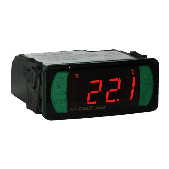
1. DESCRIPTION
It has four stages that can be applied to refrigeration or heating: the first stage, together with the third
stage, works in systems that require minimum ventilation; the third one also works as a cyclical timer;
the fourth one works as an alarm. The second, third and fourth stages work also in the following modes:
Refrigeration, heating, refrigeration (Sp1), and heating (SP1). Stage 1 can be used in soak mode and
allows configuring up to five different setpoints and the time each one will remain active. MT-543
plus accepts two types of sensor: NTC thermistor (-50 to 200 °C*), PT-100** (-99 to 300 °C). It has an
intelligent functions lock system, a mode to switch off the control functions, an internal audible alarm
(buzzer), and a configurable digital filter and serial interface for communications with Sitrad.
2. APLICATIONS
• Blood banks
• Vaccines
• Temperature multistage systems
• Beer brewing
• Air conditioners
• Datacenters
3. TECHNICAL SPECIFICATIONS
MT-543E Plus: 115~230 Vac ±10% (50/60 Hz)
Power supply
MT-543EL Plus: 12 or 24 Vac/dc +10%
Approximate consumption
0,5 VA
*NTC: -50 to 200ºC / -58 to 392ºF
Control temperature
**PT100: -99 to 300ºC / -146 to 572ºF
Operating temperature
0 to 50ºC / 32 to 122ºF
Maximum output current
OUT1, OUT2, OUT3, OUT4: 5(3)A / 250 Vac / 1/8HP
Operating humidity
10 a 90% UR (no condensation)
Dimensions (mm)
76 x 34 x 77 mm (WxHxP)
Dimensions of the clip for fixing the
71 ± 0,5 x 29 ± 0,5 mm (see item 5)
instrument
Note: Sensor cable length can be increased to up to 200 meters by the user by using a PP 2 x 24 AWG cable.
*It measures temperatures up to 200 °C using the SB59 (sold separately).
**Sensors sold separately
4. INDICATIONS AND KEYS
Led indicator
(digital output 3 on / off)
Led indicator
(digital output 2 on / off)
Led indicator
(digital output 1 on / off)
Quick access
menu key (Flatec)
Set key
e plus
MT-543
5. 5. INSTALLATION - PANEL AND ELECTRIC CONNECTIONS
Panel
(side view)
e plus
MT-543
FOUR-STAGE DIGITAL CONTROLLER WITH
ALARM, CYCLICAL TIMER, SOAK FUNCTION,
AND SERIAL COMMUNICATION
Audible
Cyclical
Functions
Control
alarm
timer
lock
Functions
Shutdown
Led indicator
(digital output 4 on / off)
Buzzer alarm indication led
Temperature unit indication
LED
Increase key
Decrease key
71
± 0,5
mm
Dimensions of the opening
to fasten the instrument
Panel (front view)
IP 65
FRONT
Serial
Degree of
Supervisory
programming
system
protection
WARNING
FOR INSTALLATIONS THAT REQUIRE WATER
TIGHTNESS, THE OPENING TO INSTALL THE
CONTROLLER MUST BE 70.5 x 29 mm MAXIMUM. THE
SIDE LATCHES MUST BE FIXED IN ORDER TO PRESS
THE SEALING GASKET TO PREVENT INFILTRATION
BETWEEN THE OPENING AND THE CONTROLLER.
SITRAD
A
B
115 Vac
5 6 7 8
connection
1
2 3 4
NTC
PT-100**
SITRAD
A
B
230 Vac
5 6 7 8
connection
1
2 3 4
NTC
PT-100**
SITRAD
A
B
e
12 Vac/dc
5 6 7 8
connection
1
2 3 4
NTC
PT-100**
SITRAD
A
B
24 Vac/dc
5 6 7 8
connection
1
2 3 4
NTC
PT-100**
6. OPERATIONS
6.1. Quick Access Menu Map
To access or browse the quick access menu, use the
displayed by the controller. With each touch the next function in the list is displayed. To confirm use the
/
key (quick touch). See chapter 6.3 for more details. The map of functions is shown below:
ADJUSTING DESIRED
TEMPERATURE (SETPOINT)
;
e plus
MT-543
;
e plus
MT-543
CONTROL FUNCTIONS
SHUTDOWN
;
e plus
MT-543
MIN. AND MAX.
TEMPERATURE RECORD
;
e plus
MT-543
6.2. Quick access keys map
When the controller is on temperature display mode, the following keys can be used as shortcuts for the
following functions:
/ <
Hold down for 2 seconds: Setpoint adjustment.
Hold down for 2 seconds: Inhibits the audible alarm and alarm output.
<
Quick touch: Maximum and minimum temperature display.
<
Hold down for 2 seconds: clear history when records are being displayed.
;
/
e
Hold down for 2 seconds: Soak Menu.
< <
Held down simultaneously: Enters function selection.
evolution
e pl us
e pl us
M T- 54 3
M T- 54 3
IMPORTANT
IT IS ESSENTIAL TO USE PROPER TOOLS IN ORDER TO AVOID
DAMAGES TO THE INSTRUMENT'S CONNECTION TERMINALS:
3/32'' (2.4 mm) SLOTTED SCREW DRIVER FOR ADJUSTMENTS
IN THE SIGNAL TERMINALS;
#1 PHILLIPS SCREW DRIVER FOR ADJUSTMENTS IN THE
POWER TERMINALS.
POWER
SUPPLY
9
10 11 12 13 14 15 16 17
0
115 Vac
POWER
SUPPLY
9
10 11 12 13 14 15 16 17
0
230 Vac
POWER
SUPPLY
9
10 11 12 13 14 15 16 17
0
12 Vac/dc
POWER
SUPPLY
9
10 11 12 13 14 15 16 17
0
24 Vac/dc
;
key (quick touch) while the temperature is being
EXIT FUNCTION
;
FUNCTION SELECTION
;
SOAK TIMES
CONFIGURATION
;
ERASE MAX. AND
MIN. VALUES
ALARM INHIBITOR
;
;
e plus
MT-543
e plus
MT-543
e plus
MT-543
e plus
MT-543
e plus
MT-543
Advertisement
Table of Contents

Related Manuals for Full Gauge Controls MT-543e plus


Summary of Contents for Full Gauge Controls MT-543e plus
- Page 1 ACCESSORIES: Only use original accessories of Full Gauge Controls. SITRAD If you have any questions, please contact our technical support. DUE TO CONSTANT EVOLUTION, FULL GAUGE CONTROLS RESERVES THE RIGHT TO CHANGE THE POWER 230 Vac 5 6 7 8 SUPPLY INFORMATION CONTAINED IN THIS MANUAL.
- Page 2 Besides operating as refrigeration or heating, Stage 3 can act as a cyclical timer or minimum ventilation. 6.3 Basic operations It has five operating modes when configured as cyclical timer: 6.3.1 Adjusting the desired temperature - Independent (F22=0): the timer cycles are according to the times configured in F20 ([COn,]) and To enter the setpoint adjustment menu, press for 2 seconds until [Set,]is displayed or use the F21 ([COff]).
- Page 3 In the soak mode, the controller operates in the configured setpoint for the chosen permanence time. 6.3.10.3 Audible warnings The permanence time count is only started when the temperature reaches the soak setpoint for the first The following audible warnings will occur during the soak control mode: time.
- Page 4 PT-100 CELSIUS FAHRENHEIT CELSIUS FAHRENHEIT Description Unit Standard Unit Standard Unit Standard Unit Standard [,F34] Minimum delay to switch on stage 4 output again sec. sec. sec. sec. [,F35] Alarm inhibition time upon power up Min. Min. Min. Min. [,F36] Time to reactivate the alarm when manually inhibited Auto Min.
- Page 5 0.1° C. This function can be switched off by setting it at the minimum value 0. Device used to establish the Interface. Repeat the procedure for terminals B and , with being the cable connection of Full Gauge Controls mesh (optional ground). Terminal of the connection block must be connected to ®...
- Page 6 If in doubt, please contact Full Gauge Controls. Products manufactured by Full Gauge Controls, as of May 2005, have a two (02) year warranty, as of the date of the consigned sale, as stated on the invoice. They are guaranteed against manufacturing defects that make them unsuitable or inadequate for their intended use.
Need help?
Do you have a question about the MT-543e plus and is the answer not in the manual?
Questions and answers