Table of Contents
Advertisement
Quick Links
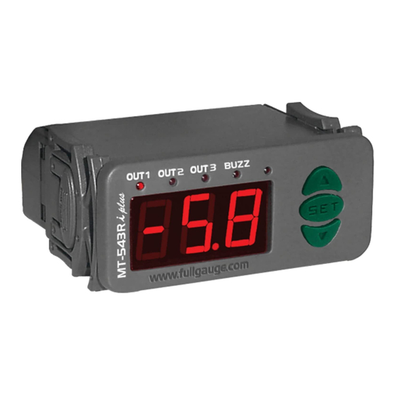
1. DESCRIPTION
MT-543Ri plus has three outputs of temperature control and a internal buzzer. Because of its
versatility, it permits that the second stage works as alarm and the third, besides to work as cyclical
timer, it can work with the first stage in systems that need minimum ventilation. Through the serial output
RS-485, it permits communication with SITRAD software.
Product complies with CE (European Union) and UL Inc. (United States and Canada)..
2. APPLICATION
• Blood banks
• Multistage temperature system
•Air conditioning
• Data centers
3. TECHNICAL SPECIFICATIONS
- Power Supply:
MT-543Ri plus - 115/230 Vac ±10% (50/60 Hz)
MT-543RiL plus - 12/24 Vac/dc
- Control Temperature:
NTC: -50 to 105 ºC (± 0.1ºC)
PT-100: -99 to 300 ºC (± 1 ºC)
- Dimensions:
71 x 28 x 71 mm
- Operating temperature:
0 to 50 ºC
- Operating humidity:
10 to 90% RH (without condensation)
- Load Current:
5(3)A/ 250Vac 1/8HP each output
CLASSIFICATION ACCORDING TO IEC60730-2-9 STANDARD:
- Temperature limit of the installation surface:
- Type of construction:
Built-in electronic controller
- Automatic action:
Type 1
- Control of pollution:
Level 2
- Impulse voltage:
1,5kV
- Temperature for the test of sphere pressure:
- Insulation:
Class II
4. PARAMETERS TABLE
Fun
Description
F01
Access code:123(one hundred and twenty-three)
F02
Offset indication
F03
Operation mode of first stage
F04
Minimum setpoint allowed to the end user (first stage)
F05
Maximum setpoint allowed to the end user (first stage)
F06
Control differential (hysteresis) of first stage
F07
Minimum delay to turn on the first stage output
F08
Operation mode of second stage
F09
Minimum setpoint allowed to the end user (second stage)
F10
Maximum setpoint allowed to the end user (second stage)
F11
Control differential(hysteresis) of second stage
F12
Minimum delay to turn on the second stage output
Delay to enable the alarm when the instrument is powered on
F13
Alarm Time (on cycle)
F14
F15
Alarm Time (off cycle)
F16
Operation mode of third stage
F17
Minimum setpoint allowed to the end user (third stage)
F18
Maximum setpoint allowed to the end user (third stage)
F19
Control differential (hysteresis) of third stage
F20
Minimum delay to turn on the third stage
F21
Time base of third stage cyclical timer
F22
Activation time for third stage cyclical timer
F23
Cyclical timer on third stage- time on
F24
Cyclical timer on third stage- time off
F25
Operation mode of cyclical timer
F26
Operation mode of Buzzer
F27
Acting point of Buzzer (inferior limit)
F28
Acting point of Buzzer (superior limit)
F29
Buzzer time on
F30
Buzzer time off
F31
Inhibition time of Buzzer during electrical supply
F32
Network equipment address RS - 485
OBS: To inhibit the alarms OUT2 and BUZZ press simultaneously
MT-543Ri plus
THEE OUTPUT DIGITAL CONTROLLER
WITH ALARM, CYCLICAL TIMER AND
SERIAL COMMUNICATION
Ver. 03
®
50°C
75°C and 125°C
NTC
PT-100
Min
Max
Unit
Min
Max
-
-
-
-
-5.0
5.0
°C
-5
0
1
-
0
-50
105
°C
-99
-50
105
°C
-99
0.1
20.0
°C
1
1
999
sec.
1
0
4
-
0
-50
105
ºC
-99
-50
105
ºC
-99
0.1
20.0
ºC
1
1
999
sec.
1
1
999
min.
1
1
999
sec.
1
1
999
sec.
1
999
-
0
2
0
-50
105
ºC
-99
300
ºC
-50
105
-99
300
0.1
20.0
ºC
1
1
999
seg.
1
999
-
0
1
0
1
999
sec.
1
999
-
1
999
1
999
1
999
-
1
999
-
0
4
0
0
2
-
0
-50
105
ºC
-99
300
ºC
-50
105
-99
300
1
999
sec.
1
999
sec.
1
999
1
999
1
999
min.
1
999
-
1
247
1
247
and
SET
.
F01 - Access code: 123 ( one hundred and twenty-three)
To change the parameters is necessary use the access code. It is not necessary to use the access code
to visualize the adjusted parameters.
F02 - Offset indication
It allows to compensate eventual shunting lines in the reading of ambient temperature proceeding from
the exchange of the sensor or cable lenght alteration.
F03 - Operation mode of first stage
0 - Refrigeration
1 - Heating
F04 - Minimum setpoint allowed to the end user (first stage)
F05 - Máximum setpoint allowed to the end user (first stage)
Electronic limits whose purpose is prevent that too high or too low setpoint temperatures are regulated.
F06 - Control differential (hysteresis) of first stage
It is the difference of temperature(hysteresis) between turn ON and turn OFF the OUT1 output.
F07- Minimum delay to turn on the first stage output
It is the minimum time that OUT1 will keep turned off, it means, space of time between the last stop and
the next start.
F08 - Operation mode of second stage
0 - Refrigeration
1 - Heating
2 - Intra-range alarm
3 - Extra-range alarm
4 - Relative extra-range alarm
F09 - Minimum setpoint allowed to the end user (second stage)
F10 - Maximum setpoint allowed to the end user (second stage)
Electronic limits whose purpose is prevent that too high or too low setpoint temperatures are regulated.
When the second stage ( F08 ) is defined as alarm, the acting points are defined in F09 and F10.
F11 - Control differential(hysteresis) of second stage
It is the difference of temperature(hysteresis) between turn ON and turn OFF the output OUT2.
Unit
-
-
F12- Minimum delay to turn on the second stage output
5
°C
It is the minimum time that the output OUT2 will keep turned off, it means, the space of time between the
1
-
last stop ant the next start.
300
°C
300
°C
F13 - Delay to enable the alarm when the instrument is powered on
40
°C
During this time the alarm is kept turned off waiting that the system reaches the working control
999
sec.
temperature.
4
-
F14 - Alarm time (on cycle)
300
ºC
It allows to adust the time that OUT2 output will keep turned on. This function acts only with F8
300
ºC
configurated as alarm.
40
ºC
999
sec.
F15 - Alarm time (off cycle)
999
min.
It allows to adust the time that OUT2 output will keep turned off.This function acts only with F8
999
sec.
configurated as alarm. To keep the alarm always activated just set "0" in this function.
sec.
-
F16 - Operation mode of third stage
2
0 - Refrigeration
ºC
1 - Heating
ºC
2 - Cyclical Timer
40
ºC
sec.
-
1
F17 - Minimum setpoint allowed to the end user (third stage)
sec.
F18 - Maximum setpoint allowed to the end user (third stage)
-
Electronic limits whose purpose is prevent that too high or too low setpoint temperatures are regulated.
-
-
4
F19 - Control differential (hysteresis) of third stage
2
-
It is the difference temperature (hysteresis) between turn ON and turn OFF the output OUT3.
ºC
ºC
F20- Minimum delay to turn on the third stage
sec.
It is the minimum time that the output OUT3 will keep turned off, it means, the space of time between the
sec.
last stop and the next start.
min.
-
F21-Time base of third stage cyclical timer
0 - seconds
1 - minutes
F22 - Activation time of third stage cyclical timer
This function depends of F25. Every time that the temperature reach the configured value in
configured time in this function is respected, to be activated the cyclical timer after. To activate the timer
when
is reached just set "0" in this function.
UL-Underwriters Laboratories
, the
Advertisement
Table of Contents

Related Manuals for Full Gauge Controls MT-543Ri plus


Summary of Contents for Full Gauge Controls MT-543Ri plus
- Page 1 1. DESCRIPTION To change the parameters is necessary use the access code. It is not necessary to use the access code MT-543Ri plus has three outputs of temperature control and a internal buzzer. Because of its to visualize the adjusted parameters.
- Page 2 F31 - Inhibition time of Buzzer during electrical supply MT-543Ri plus MT-543RiL plus 72 mm It is the time were the alarm will kept turned off even if in alarm contitions. 6 - 7...
- Page 3 PROTECTIVE VINYL: This adhesive vinyl (included inside the packing) protects the instruments against water drippings, as in commercial refrigerators, for example. Do the application after finishing the electrical connections. Remove the protective paper and apply the vinyl on the entire superior part of the device, folding the flaps as indicated by the arrows.
Need help?
Do you have a question about the MT-543Ri plus and is the answer not in the manual?
Questions and answers