Table of Contents
Advertisement
Quick Links
1. DESCRIPTION
e
The MT-444
Faston has 3 recipe options, each with its control temperature and their
differentials (hysteresis), as well as specific keys for triggering / disabling and turn the lamp on / off, in
addition to fast freezing functionality. It also has a digital filter, which has the purpose of simulating an
increase in mass in the ambient sensor (S1), delaying its response time (thermal inertia) and avoiding
unnecessary compressor trips. It also includes an intelligent blocking of functions and a shutdown mode
of the control functions.
Product conforming to UL Inc. (United States and Canada).
2. SAFETY RECOMMENDATIONS
- Check the controller for correct fastening;
- Make sure that the power supply is off and that it is not turned on during the controller installation;
- Read the present manual before installing and using the controller;
- Use adequate Personal Protective Equipamenet (PPE);
- For application at sites subject to water spills, such as refrigerated counters, install the protecting vinyl
supplied with the controller;
- For protection under more critical conditions, we recommend the Ecase cover, which we make
available as an optional item (sold separately);
- The installation procedures should be performed by a qualified technician.
3. APPLICATIONS
• Beverage displays;
• Reach-in coolers;
• Refrigeration counters;
• Up right freezers.
4.TECHNICAL SPECIFICATIONS
Power supply
Approximate consumption
Setpoint Temperature
Operating humidity
Digital input
Maximum dimensions (**) (mm)
Cutouts dimensions (mm)
(*) Admissible variation in relation to the voltage rating.
(**) Maximum dimensions without connectors.
UL / CSA Standards
Operating Temperature
Maximum current per output COMP
Maximum current per output
DEFR / FAN / LIGHT
Note: Only Coating controllers from version 04 onwards meet Standard 60730-1.
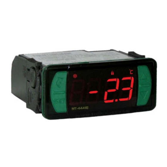
5. INDICATORS AND KEYS
Refrigeration indicator LED
Light indicator LED
Power-saving mode indicator LED
Quick Access
Menu Key (Flatec)
Set Key
e
MT-444
6. WIRING DIAGRAM
Image I - Connection 115 Vac
7
8
9 10 11 12 13 14
1 2
3 4 5 6
D1/S3
LIGHT
FAN
S1
S2
Image III - Connection 12 Vac/dc
7
8
9 10 11 12 13 14
1 2
3 4 5 6
D1/S3
LIGHT
S1
S2
12 Vac/dc
MT-444
DIGITAL REFRIGERATION
CONTROLLER
Connector
Fast
Power-saving
On/off
for quick
Freezing
mode
coupling
MT-444E Faston: 115 or 230Vac ±10%(*) (50/60 Hz)
MT-444EL Faston: 12 or 24Vac/dc +10%(*)
3.4 VA
- 50 to 75°C (-58 to 167°F)
10 to 90% RH (without condensation)
Dry contact type configurable
76 x 34 x 84 (WxHxD)
X = 71±0,5 Y = 29±0,5 (see Image V)
873
60730-1
-10 a 50°C / 14 a 122°F
-10 a 60°C / 14 a 140°F
12(8)A / 240V 1HP
12(8)A / 240V 1HP
3A / 240Vac 720W
5A / 250Vac 1200W
5(3)A / 240Vac
1/8HP / 250Vac
5W LED / 240Vac
1A E-Ballast / 250Vac
Fan indicator LED
Defrost indicator LED
Temperature unit indicator LED
Image II - Connection 230 Vac
1 2
3 4 5 6
DEFR
COMP
S1
S2
115 Vac
Image IV - Connection 24 Vac/dc
1 2
3 4 5 6
FAN
DEFR
COMP
S1
S2
Power
supply
e
Faston
Buzzer
Functions
Control
light
lock
functions
shutdown
NEW CONNECTION SYSTEM (QUICK COUPLING):
CONNECTION:
- Hold the wire near its end and insert it into the
desired slot.
- If necessary, press the bottom to assist the
connection.
NOTE:
- In the connectors 1 to 6 the maximum wire
diameter that can be used is 1,5mm².
- The wires must be tinned or use Rocket Pin
terminals with a maximum diameter of 0,75mm².
6.1. Temperature sensors connection
- Connect the sensor S1 wires to terminals "1 and 2", wires of sensor S2 to terminals "3 and 4" and wires
of sensor S3 to terminals ''5 and 6'': the polarity is not relevant.
- Length of the sensor cables can be increased by user himself to up to 200 meters, using a PP 2x24 AWG
cable.
6.2. Recommendations of IEC60364 standard
a) Install overload protectors in the controller supply.
b) Install transient suppressors – suppressor filter RC – in the circuit to increase the service life of the
controller relay. See connection instructions of the filter on the previous page.
c) The sensor cables may be together, but not in the same conduit where the power supply of the
controller and/or of the loads passes through.
7. FIXING PROCEDURE
a) Cutout the panel plate (Image V - item 13) where the controller will be fixed, with dimensions
= 71±0,5 mm and Y = 29±0,5 mm;
b) Remove the side locks (Image VI - item 13): To do this, squeeze the elliptical central part (with the Logo
Full Gauge Controls) and move the latches back;
c) Pass the wires through the cutout of the plate (image VII - Item 13) and make the electrical installation
as described in item 6;
d) Insert the controller into the panel cutout, from the outside in;
e) Replace the latches and push then until they are pressed against the panel, securing the controller to
the housing (see arrow in Figure VI - item 13);
f) Adjust the parameters as described in item 9.
WARNING: for installations requiring liquid-tight sealing, the cut-off for the installation of the
controller should be at must 70.5x29mm. The side latches must be secured so that they press the
rubber sealing to prevent infiltration between the cutout and the controller.
Upper key
Vinyl protector - Image IX (item 13)
Protects the controller should when installed in a place with splashing water, such as in refrigerated
counters. This adhesive vinyl accompanies the instrument, on the packaging.
IMPORTANT: Apply only after completing electrical connections.
Lower key
a) Retract the lateral locks (Image VI - item 13);
b) Remove the protective film from the adhesive side of the vinyl;
c) Apply the vinyl over the whole top, folding the flaps, as indicated by the arrows - Image IX (item 13);
d) Reinstall the latches.
NOTE: The vinyl is transparent, allowing to visualize the electric scheme of the instrument.
7
8
9 10 11 12 13 14
D1/S3
LIGHT
FAN
DEFR
COMP
7
8
9 10 11 12 13 14
D1/S3
LIGHT
FAN
DEFR
COMP
24 Vac/dc
IP 65
FRONT
e
e
MT -4 44
MT -4 44
Serial
Protection
Programming
level
FASTON and PUSH-IN FAST
DISCONNECT:
- To disconnect the cord, press the bottom and
remove it.
230 Vac
Controller power supply
Use the pins according to table below, considering the set version:
Pins
9 and 10
9 and 11
The sensor S1 must be in the ambient.
Power
The sensor S2 must be placed in the evaporator
supply
through metallic cramp.
evolution
E251415
BOTTOM
WIRE INPUT
The wire should be picked
in 5 mm and tinned.
Terminal Rocket Pin.
X
MT-444E Faston
MT-444EL Faston
115 Vac
12 Vac/dc
230 Vac
24 Vac/dc
Advertisement
Table of Contents

Related Manuals for Full Gauge Controls MT-444E Faston


Summary of Contents for Full Gauge Controls MT-444E Faston
- Page 1 - The wires must be tinned or use Rocket Pin • Up right freezers. terminals with a maximum diameter of 0,75mm². 4.TECHNICAL SPECIFICATIONS Terminal Rocket Pin. MT-444E Faston: 115 or 230Vac ±10%(*) (50/60 Hz) Power supply MT-444EL Faston: 12 or 24Vac/dc +10%(*) 6.1. Temperature sensors connection Approximate consumption 3.4 VA...
- Page 2 8. QUICK ACCESS MENU AND BASIC OPERATIONS 8.6 Visualização da temperatura no sensor S2 (evaporador) 8.1. Quick Access Menu Map A temperatura no sensor S2 (evaporador) pode ser visualizada pressionando a tecla (toque curto), até que apareça a mensagem [Sns2]. Caso este sensor esteja desabilitado, será exibida a You can navigate through the function menus by pressing the key (Flatec).
- Page 3 9. ADVANCED OPERATIONS 8.10 Maximum and Minimum Temperature Recording 9.1 Changing the configured setup The Maximum and Minimum Temperature Record can be viewed by pressing the key until the The functions menu can be accessed through the quick access menu, option [Func] or by pressing message [rEg,] is displayed (see item 8.1 on the map) : <...
- Page 4 CELSIUS (FAHRENHEIT) FUNCTION DESCRIPTION UNIT. DEFAULT [,f13] Control differential of power-saving setpoint (r1) This is the difference between turning refrigeration OFF and BACK ON in power-saving [,f14] 0.1 (1) 20.0 (36) ºC (°F) 3.0 (5) Control differential of power-saving setpoint (r2) mode.
- Page 5 CELSIUS (FAHRENHEIT) FUNCTION DESCRIPTION UNIT. DEFAULT With this function activated, you can make the output FAN operate as a second defrost output. This output is activated during the execution of the pre-defrost, defrost and [,f47] [Off,] [On,,] [Off,] Enable second defrost output drainage.
- Page 6 CELSIUS (FAHRENHEIT) FUNCTION DESCRIPTION UNIT. DEFAULT Compressor ON time in case of error on sensor S1 [,f67] min. If the room sensor (sensor S1) is disconnected or out of its measuring range, the (room) compressor will turn on and off according to the setup configured in these functions. Compressor OFF time in case of error on sensor S1 [,f68] min.
- Page 7 Flashing LED [OFF,] Control routines turned off. Load [AOPN] Open door alarm. [ECal] Contact Full Gauge Controls. 13. ANNEXES - Reference Images [pppp] Reconfigure the function values. Image V 11. GLOSSARY OF ACRONYMS - °C: Temperature in Celsius degrees. - °F: Temperature in Fahrenheit degrees.
- Page 8 If in doubt, please contact Full Gauge Controls. Products manufactured by Full Gauge Controls, as of May 2005, have a two (02) year warranty, as of the date of the consigned sale, as stated on the invoice. They are guaranteed against manufacturing defects that make them unsuitable or inadequate for their intended use.
Need help?
Do you have a question about the MT-444E Faston and is the answer not in the manual?
Questions and answers