Table of Contents
Advertisement
Quick Links
WARNING
BEFORE INSTALLING THE CONTROLLER, WE RECOMMEND READING THROUGH THE
ENTIRE INSTRUCTION MANUAL IN ORDER TO AVOID POSSIBLE DAMAGE TO THE
PRODUCT.
PRECAUTIONS WHEN INSTALLING THE PRODUCT:
Before performing any procedure on this instrument, disconnect it from the mains;
Ensure that the instrument has adequate ventilation and avoid installation in panels containing
devices that may cause it to operate outside the specified temperature limits;
Install the product away from sources that may generate electromagnetic disturbances such as:
motors, contactors, relays, solenoid valves, etc;
AUTHORIZED SERVICE:
The installation or maintenance of the product must be performed by qualified professionals only;
ACCESSORIES:
Only use original Full Gauge Controls accessories.
If you have any questions, please contact technical support.
DUE TO YOUR CONSTANT EVOLUTION, THE FULL GAUGE CONTROLS RESERVES THE RIGHT TO
CHANGE THE INFORMATION CONTAINED IN THIS MANUAL AT ANY TIME WITHOUT NOTICE.
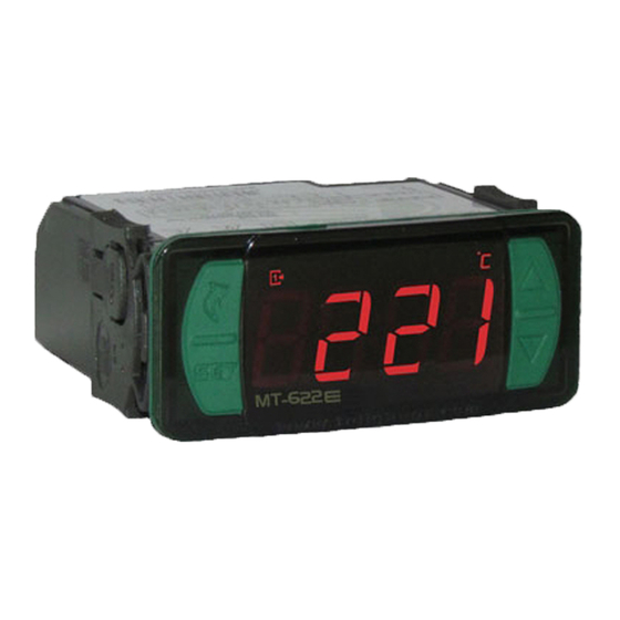
1. DESCRIPTION
e
The MT-622
is a temperature controller that uses a thermocouple type J as sensor, has two
outputs for temperature control and internal buzzer. It also has a timer that can operate in different
modes, triggered by digital inputs, which indicates the end time of one or two processes.
The first stage can use a cyclic preheating mode, and the second stage can function as an alarm, a
cyclic timer or end of process indication. It is also possible to use 5 configurable recipes, which allows to
quickly change the values for the temperature setpoint and the hysteresis of the first stage and the
processing time.
Product complies with UL Inc. (United States and Canada).
2. APPLICATIONS
• Fryers
• Ovens
3. TECHNICAL SPECIFICATIONS
Power supply
Control temperature
Operating temperature
Current output
Resolution
Operating humidity
Sensor
Dimensions (mm)
Dimensions of the clipping for
fixing of the instrument
4. INDICATIONS AND KEYS
Internal buzzer drive indicator LED
Output OUT2 drive indicator LED
Output OUT1 drive indicator LED
Quick access
menu (Flatec)
Set key
e
MT-622
5. INSTALLATION - ELECTRICAL CONNECTIONS AND PANEL
(Side View)
MT-622
TWO STAGE DIGITAL CONTROLLER
WITH ALARM AND CYCLIC TIMER
AND PROCESS TIMER
Buzzer
Functions
Control functions
lockdown
shutdown
MT-622E: 115/230 Vac ±10% (50/60 Hz)
MT-622EL: 12/24 Vac/dc +10% (50/60 Hz)
0 to 600°C / 32 to 1112°F
0 to 50 ºC / 32 to 122ºF
OUT 1: 16(8)A / 250 Vac 1HP - 4000W
OUT 2: 5(3)A / 250 Vac 1/8HP
1ºC / 1ºF
10 to 90% UR (non-condensing)
J type Thermocouple (sold separately)
76 x 34 x 77 mm (WxHxD)
71 ± 0,5 x 29 ± 0,5 mm (see item 5)
Pre-process/process timer indicator LED
Function locks indicator LED
Temperature unit indicator LED
71
± 0,5
mm
Dimension of the clipping
for setting of the
instrument in panel
Panel (Front View)
Panel
e
IP 65
FRONT
Serial
Protection
programming
level
ATTENTION
FOR INSTALLATIONS WHERE A SEALING IS REQUIRED
TO AVOID LIQUID CONTACT, THE CUT FOR THE
CONTROLLER MUST BE OF 70,5X29mm MAXIMUM. THE
SIDE LOCKS MUST BE FIXED SO IT PRESSES THE
RUBBER SEALING AVOIDING INFILTRATION BETWEEN
THE CUT AND THE CONTROLLER.
Connection
115 Vac
12 Vac/dc
Connection
230 Vac
24 Vac/dc
6. OPERATIONS
6.1 Facilitated menu map
By pressing ; it is possible to navigate through the function menus. For more details, see chapter 6.3.
See the functions map below:
ADJUSTING THE DESIRED
TEMPERATURE (SETPOINT)
;
e
MT-622
LOCK FUNCTION
;
e
MT-622
CONTROL FUNCTIONS
SHUTDOWN
;
e
MT-622
Increase key
6.2 Facilitated key map
When the controller is on display temperature, the following shortcut keys are used for the following
functions:
Decrease key
/
Pressed 2 seconds: Adjusts the setpoint or change of recipe.
/
Short press: Inhibits alarm and buzzer (if activated).
<
Short press: Maximum and minimum temperatures display.
<
Pressed second
Short press: With process timer driven -
/
>
Short press: Starts process.
<
Short press: Ends process.*
< <
Enter the function selection.
*
If the operation mode of the 2nd stage is configured as steam
becomes 4 seconds to end the process.
e
e
M T- 62 2
M T- 62 2
IMPORTANT
THE USE OF APPROPRIATE TOOLS IS ESSENTIAL TO AVOID
DAMAGE IN THE CONNECTION AT INSTRUMENT TERMINALS:
SCREWDRIVER SLOT 3/32''(2.4mm) FOR ADJUSTMENTS IN THE
SIGNAL TERMINALS;
SCREWDRIVER PHILLIPS #1 FOR ADJUSTMENTS IN THE POWER
TERMINALS;
DIG3
DIG4
5A
5 6 7 8
POWER SUPPLY
9
10 11 12 13 14 15 16 17
1
2 3 4
-
+
DIG1
DIG2
Thermocouple
''J''
Type
*
DIG3
DIG4
5A
5 6 7 8
POWER SUPPLY
9
10 11 12 13 14 15 16 17
1
2 3 4
-
+
DIG1
DIG2
Thermocouple
''J''
Type
*
Pins
12 and 13
12 and 14
REGISTRATION OF
TEMPERATURE
MÍN. AND MÁX.
;
e
MT-622
1
: Steam output activation.
Switches display between temperature and remaining time.
(F28=11), the time for pressing the key
evolution
E251415
16A
115 Vac
C2
C1
12 Vac/dc
16A
230 Vac
C2
C1
24 Vac/dc
POWER SUPPLY
MT-622E
MT-622EL
115 Vac
12 Vac/dc
230 Vac
24 Vac/dc
and
loads
C1
C2
*Sensor sold separately
EXIT THE MENU
;
e
MT-622
FUNCTION SELECTION
;
e
MT-622
CLEAR VALUES MÍN. AND
MÁX.
;
e
MT-622
Advertisement
Table of Contents

Related Manuals for Full Gauge Controls MT-622E


Summary of Contents for Full Gauge Controls MT-622E
- Page 1 Only use original Full Gauge Controls accessories. If you have any questions, please contact technical support. DIG1 DIG2 DUE TO YOUR CONSTANT EVOLUTION, THE FULL GAUGE CONTROLS RESERVES THE RIGHT TO 115 Vac Thermocouple 12 Vac/dc CHANGE THE INFORMATION CONTAINED IN THIS MANUAL AT ANY TIME WITHOUT NOTICE.
- Page 2 6.3 Basic operations 6.3.4 Control Functions Shutdown With the shutdown of the control functions the controller will operate only as a temperature indicator and 6.3.1Adjusting the desired temperature (setpoint) and time process output relay stays off. If it is configured not to use formulas (F03= [no,,]): The way to operate the control functions shutdown depends on the parameter setting “[,F53]- - Press and hold the key for two seconds, until the message [Set,]appears;...
- Page 3 CELSIUS FAHRENHEIT Standard Standard Description Unit Unit F27] Maximum time to preheat min. min. [,F28] Operational Mode of the 2nd stage [,F29] Minimum setpoint allowed to the end user (2nd stage) °C 1112 °F [,F30] Maximum setpoint allowed to the end user (2nd stage) °C 1112 °F...
- Page 4 F29 - Minimum setpoint allowed to the end user (2nd stage): F49 - Operational mode of digital inputs: F30 - Maximum setpoint allowed to the end user (2nd stage): This function allows to set the operating mode of the digital inputs: [,,,0] - 1 Timer - DIG1 ( START) and DIG2 (STOP): The electronic limits have the purpose of preventing the use, by mistake, of very high or low temperature Digital input 1 (DIG1) or...
- Page 5 8.3 Extension Frame The Full Gauge Controls extension frame allows the installation of Evolution / Ri line with measures 76x34x77 mm (dimensions of the clipping for fixing in the extension frame is 71x29mm) in varied situations, since it eliminates precision cut to embed the instrument.
Need help?
Do you have a question about the MT-622E and is the answer not in the manual?
Questions and answers