Advertisement
Quick Links
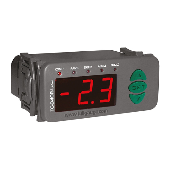
1. DESCRIPTION
TC-900Ri clock is a temperature controller for refrigerated products. It automates defrost processes
according to the need of the installation, saving energy. It has two sensors, one for room temperature and
another that, fixed to the evaporator, controls the end of defrost and fan return. In addition, it has an
internal real time clock that enables creating an agenda with up to eight daily defrosts for each day of the
week. The controller's internal battery guarantees its synchronism, even during power shortage, tor many
years. It has an output for serial communication, and can be managed remotely through Sitrad ® via
Internet.
Product complies with CE (European Union), NSF (
Canada).
2. APPLICATION
• Refrigeration chambers
• Counters
3. TECHNICAL SPECIFICATIONS
- Power Supply: TC-900Ri clock -115/230 Vac ±10% (50/60 Hz)
TC-900RiL clock -12/24 Vac/dc
- Control temperature: -50 to 75°C / -58 to 167°F
- Resolution: 0.1ºC from -10 to 75ºC and 1ºC outside this range / 1°F in all range
- Operating temperature: 0 to 50 ºC / 32 to 122°F
- Operation humidity: 10 to 90% RH (without condensation)
- Dimensions: 71 x 28 x 71mm
- Load current (outputs):
REFR: 5(3)A / 250Vac 1/8HP (compressor, solenoid valve or contactor)
FANS: 5(3)A / 250Vac1/8HP (evaporator fans)
DEFR: 5(3)A / 250Vac (defrost resistance or hot gas)
- Sensors:
S1: ambient sensor (black cable)
S2: evaporator sensor (gray cable)
CLASSIFICATION ACCORDING TO IEC60730-2-9 STANDARD:
- Temperature limit of the installation surface: 50º C
- Type of construction: Built-in electronic controller
- Automatic action: Type 1
- Control of pollution: Level 2
- Impulse voltage: 1,5kV
- Temperature for the test of sphere pressure: 75ºC and 125ºC
- Insulation: Class II
4.
CONFIGURATIONS
4.1 - Control temperature adjust (SETPOINT):
- Press
SET
for 2 seconds until appears
appear.
- Use
and
to change the value and then press
4.2 - Parameters table
Fun
Defrost by programmed time (weekly schedule)
Control differential (hysteresis)
Minimum setpoint allowed to the end user
Maximum setpoint allowed to the end user
Delay when the instrument is powered on
Act point of low ambient temperature alert (S1)
Act point of high ambient temperature alert (S1)
Refrigeration time (interval between defrosts)
Compressor delay after on (on - off)
Compressor delay after off (off - on)
Compressor status with detached ambient sensor (S1)
Defrost when the instrument is powered on
Evaporator temperature (S2) for end defrost
Maximum defrost duration (for security)
Fan turned on during defrost
Defrost type
Locked temperature indication (S1) during defrost
Draining time (dripping of defrost water)
Evaporator temperature (S2) for fan return after draining
Maximum time of fan return after draining (fan-delay)
Fan on with compressor off (refrigeration)
Fan stopped for high temperature in the evaporator (S2)
Offset indication for ambient sensor (S1)
Network equipment address RS - 485 (serial communication)
TC-900Ri clock
CONTROLLER FOR REFRIGERATION
WITH REAL TIME DEFROSTING
AND SERIAL OUTPUT
Ver.10
United States)
and UL Inc. (United States and
, and release it after that. The adjusted temperature will
to record it.
SET
Description
4.2.1 - Parameters description
F01 - Defrost by programmed time (weekly schedule)
This function allows that the defrosts scheduled by time are enabled.
"O" = The defrosts normally happen after the end of the refrigeration stage.
"1" = The defrosts are activated by the programmed time that is set in the weekly schedule.
F02 - Control differential (hysteresis)
It is the difference of temperature (hysteresis) between to turn OFF and turn ON the refrigeration output.
Exemple: To control the temperature in 4.0°C with differential of 1.0°C. Soon, the refrigeration will be
turned off in 4.0°C and turned on again in 5.0°C (4.0+1.0)
F03 - Minimum setpoint allowed to the end user
F04 - Maximum setpoint allowed to the end user
Electronic limits whose purpose is prevent that too high or too low setpoint temperatures are
regulated.
F05 - Delay when the instrument is powered on
When the instrument is powered on, its control is kept disabled during a time, delaying the start of
process. During this time, it works only as temperature indicator. It serves to prevent demand of electric
energy peaks, in case of lack or return of the same and when exists a lot of equipment connected on the
same net. For this, just adjust different times for each equipment. This delay may be of compressor or
defrost (when exist defrost on turn on).
F06 - Act point of low ambient temperature alert
F07 - Act point of high ambient temperature alert
If the ambient temperature (S1) reaches this point during the refrigeration, this will be visually signaled
by the indication of a blinking light on the display.
F08 - Refrigeration time (interval between defrosts)
It is the time which compressor will turn on and turn off only for ambient temperature and starts to
becounted when the fan is turned on , after fan-delay stage (fan return after draining).
Caution: The defrost will only begin if the temperature indicated in S2 (evaporator sensor) is less than
indicated in F13.
F09 - Compressor delay after on (on-off)
It is the minimum time that compressor will keep on, it means, space of time between the last drive and
the next stop. It serves to prevent high voltage events in the electric network.
CELSIUS
Min
Max
Unit
Standard
0 - no
1 - yes
-
0 - no
1 - yes
°c
0.1
20.0
2.0
-50
F04
°c
-50.0
F03
75.0
°c
75.0
0
30
min.
0
-50.0
75.0
°c
-50.0
°c
-50.0
75.0
75.0
1
999
min.
240
0
999
sec.
0
0
999
sec.
0
-
0 - off
1 - on
1 - on
0 - off
0 - no
1 - yes
-
0 - no
0 - no
-50.0
75.0
°c
40.0
0=disable
90
min.
0=disable
45
-
0 - no
1 - yes
0 - no
0 - no
0 -
0 -
0 -
electric
1- hot gas
-
electric
0 - no
1 - yes
-
0 - no
0 - no
0
30
min.
10
-50
75.0
°C
0.0
0
30
min.
1
0 - no
1 - yes
-
1 - yes
0 - no
-50
75.0
°C
50.0
-20.0
20.0
°C
0.0
001
247
-
001
FAHRENHEIT
Min
Max
Unit
Standard
1 - yes
-
1 - yes
1
36
°F
4
-58
F04
°F
-58
F03
167
°F
167
0
30
min.
0
-58
167
°F
-58
-58
167
°F
167
1
999
min.
240
0
999
sec.
0
0
999
sec.
0
1 - on
-
1 - on
1 - yes
0 - no
-
-58
167
°F
104
90
min.
45
1 - yes
-
0 - no
1- hot gas
-
0 -
electric
electric
-
1 - yes
0 - no
min.
0
30
10
°F
-58
167
32
0
30
min.
1
-
1 - yes
1 - yes
°F
-58
167
122
°F
-36
36
0
-
001
247
001
COMPONENT
UL-Underwriters Laboratories
Advertisement

Subscribe to Our Youtube Channel
Related Manuals for Full Gauge Controls TC-900Ri clock


Summary of Contents for Full Gauge Controls TC-900Ri clock
- Page 1 1. DESCRIPTION 4.2.1 - Parameters description TC-900Ri clock is a temperature controller for refrigerated products. It automates defrost processes F01 - Defrost by programmed time (weekly schedule) according to the need of the installation, saving energy. It has two sensors, one for room temperature and another that, fixed to the evaporator, controls the end of defrost and fan return.
- Page 2 F10 - Compressor delay after off (off-on) 4.2.2 - Advanced function adjustment It is the minimum time that compressor will keep off, it means, space of time between the last stop and the a) Hold at the same time the for 2 seconds until appears, them let go, soon the next drive.
- Page 3 , being the cable shield. Device used to establish the The terminal of distribution box must be connected to the respective terminals connection Full Gauge Controls’ - Maximum defrost duration (F14 = 90 min) ® each instrument. instruments with the Sitrad...
- Page 4 - The sensor S1 (black) must be in the ambient. PROTECTIVE VINYL: - The sensor S2 (gray) must be placed in the evaporator through metallic cramp. - The sensor cable length can be increased by the user until 200 meters using the PP 2 x 24 AWG cable. This adhesive vinyl (included inside the packing) protects the instruments against IMPORTANT water drippings, as in commercial refrigerators, for example.
Need help?
Do you have a question about the TC-900Ri clock and is the answer not in the manual?
Questions and answers