Full Gauge Controls TC-900Ri, TC-900RiL - Digital Controller Manual
- Manual (4 pages)
Advertisement
DESCRIPTION
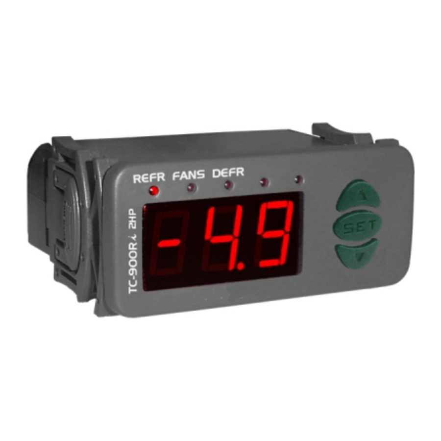
TC-900Ri is a control for low temperature ventilated units which automates defrosting processes, providing great energy saving.
It has two sensors, one for environment temperature and other that, mounted to the evaporator, commands the end defrost process and puts the fans back to work. Product in agreement with CE (European Community) and UL Inc. (USAand Canada).
APPLICATION
- Counters
- Refrigerating balconies
TECHNICAL SPECIFICATIONS
- Power supply:
- TC-900Ri - 115/230 Vac ±10% (50/60 Hz)
- TC-900RiL - 12/24 Vac/dc
- Control temperature: -50 to 75°C
- Operating temperature: 0 to 50°C
- Operating humidity: 10 to 90% RH (without condensation)
- Resolution: 0.1°C from -10 to 75°C and 1°C outside this range
- Load current (outputs):
- REFR: 5(3)A/ 250Vac 1/8HP (compressor, solenoid valve or contactor)
- FANS: 5(3)A/ 250Vac 1/8HP (evaporator fans)
- DEFR: 5(3)A/ 250Vac (defrost - resistance or hot gas)
- Dimensions: 71 x 28 x 71mm
- Sensors:
- S1: ambient sensor (black cable)
- S2: evaporator sensor (gray cable)
CLASSIFICATION ACCORDING TO IEC60730-2-9 STANDARD:
- Temperature limit of the installation surface: 50°C
- Type of construction: Built-in electronic controller
- Automatic action: Type 1
- Control of pollution: Level 2
- Impulse voltage: 1,5kV
- Temperature for the test of sphere pressure: 75°C and 125°C
- Insulation: Class II
CONFIGURATIONS
Control temperature adjust (SETPOINT)
- Press
![]() for 2 seconds until appears
for 2 seconds until appears ![]() , and release it after that. The adjusted operation temperature will appear.
, and release it after that. The adjusted operation temperature will appear. - Use
![]() and
and ![]() to change the value and then press
to change the value and then press ![]() to record it.
to record it.
 for 2 seconds until appears
  , and release it after that. The adjusted operation
 Parameters table
| Fun | Description | Min | Max | Unid |
| F01 | Access code: 123 (one hundred and twenty-three) | - | - | - |
| F02 | Control differential (hysteresis) | 0.1 | 20.0 | º C |
| F03 | Offset indication for ambient sensor | -20 | 20.0 | º C |
| F04 | Minimum setpoint allowed to the end user | -50 | 75.0 | º C |
| F05 | Maximum setpoint allowed to the end user | -50 | 75.0 | º C |
| F06 | Delay when the instrument is powered on | 0 | 30 | min. |
| F07 | Act point of high ambient temperature alert | -50 | 75.0 | º C |
| F08 | Refrigeration time (interval between defrosts) | 1 | 999 | min. |
| F09 | Compressor delay after on (on - off) | 0 | 999 | sec. |
| F10 | Compressor delay after off (off - on) | 0 | 999 | sec. |
| F11 | Compressor status with detached ambient sensor (S1) | 0 - off | 1 - on. | - |
| F12 | Defrost when the instrument is powered on | 0 - no | 1 - yes | - |
| F13 | Evaporator temperature (S2) for end defrost | -50 | 75.0 | º C |
| F14 | Maximum duration of defrost (for security) | 0=disable | 90 | min. |
| F15 | Fan turned on during defrost | 0 - no | 1 - yes | - |
| F16 | Defrost type | 0 - electric | 1 - hot gas | - |
| F17 | Locked temperature indication (S1) during defrost | 0 - no | 1 - yes | - |
| F18 | Draining time (dripping of defrost water) | 0 | 30 | min. |
| F19 | Evaporator temperature (S2) for fan return after draining | -50 | 75.0 | º C |
| F20 | Maximum time of fan return after draining (fan-delay) | 0 | 30 | min. |
| F21 | Fan on with compressor off (refrigeration) | 0 - no | 1 - yes | - |
| F22 | Fan stopped for high temperature in the evaporator | -50 | 75.0 | º C |
Parameters description
F01 - Access code (123)
To change the parameters it is necessary to use the access code. It is not necessary to use the access code to visualize the adjusted parameters.
F02 - Control differential (hysteresis)
It is the difference of temperature (hysteresis) between to turn OFF and turn ON the refrigeration output.
Example: To control the temperature in 4.0°C with differential of 1.0°C. Soon, the refrigeration will be turned off in 4.0°C and turned on again in 5.0°C (4.0 + 1.0)
F03 - Offset indication for ambient sensor
It allows to compensate eventual shunting lines in the reading of ambient temperature (S1) proceeding from the exchange of the sensor or cable length alteration.
F04 - Minimum setpoint allowed to the end user
F05 - Maximum setpoint allowed to the end user
Electronic limits whose purpose is prevent that too high or too low setpoint temperatures are regulated.
F06 - Delay when the instrument is powered on
When the instrument is powered on, its control is kept disabled during a time, delaying the start of process. During this time, it works only as temperature indicator. It serves to prevent demand of electric energy peaks, in case of lack or return of the same and when exists a lot of equipment connected on the same net. For this, just adjust different times for each equipment. This delay may be of compressor or defrost (when exist defrost on turn on).
F07 - Act point of high ambient temperature alert
If the ambient temperature (sensor S1) reaches this point during refrigeration, this will be signaled visually through the indication blinking on display.
F08 - Refrigeration time (interval between defrosts)
It is the time which compressor will turn on and turn off only for ambient temperature and starts to be counted when the fan is turned on, after fan-delay stage (fan return after draining).
F09 - Compressor delay after on (on-off)
It is the minimum time that compressor will keep on, it means, space of time between the last drive and the next stop. It serves to prevent high voltage events in the electric network.
F10 - Compressor delay after off (off-on)
It is the minimum time that compressor will keep off, it means, space of time between the last stop and the next drive. It serves to alliviate the discharge pressure and to increase the time of useful life of the compressor.
F11 - Compressor status with detached ambient sensor (S1)
If the ambient sensor (S1) will be danified or outside the specified range, the compressor assumes the configured status in this function.
Example: For counters of fruits, it is better to keep the compressor off. In counters of meat it is better to keep the compressor on.
F12 - Defrost when the instrument is powered on
It makes possible the accomplishment of a defrost at the moment that controller is energized, for example, in the return of electrical energy (in case of energy lack)
F13 - Evaporator temperature (S2) for end defrost
If the temperature in the evaporator (sensor S2) reaches the adjusted value, the end of defrost will be for temperature. With this, the defrost process is optimized.
F14 - Maximum duration of defrost (for security)
This function serves to adjust the maximum value of time for defrost. If evaporator temperature does not reach the configured value in F13 in this period a point will blink in the right down side of display indicating that end of defrost ocurred for time and not for temperature.
The end of defrost by time (which is not desired) can happen on the following situations:
- Adjusted temperature (F13) too high
- Maximum time of defrost (F14) too short
- Detached sensor or without contact with evaporator
F15 - Fan turned on during defrost
It makes possible the fan functioning during defrost.
Example: Natural defrost or by resistances installed outside the evaporator.
F16 - Defrost type
"0" = Electrical defrost (resistances), where the defrost output is active. "1" = Defrost by hot gas, where compressor and defrost outputs are actives.
F17 - Locked temperature indication (S1) during defrost
This function prevents that ambient temperature elevation during defrost be visualized, keeping the last indication before defrost. The indication is released again in the initial of refrigeration cycle, after fandelay.
F18 - Draining time (dripping of defrost water)
Necessary time for dripping, it means, for draining the last water drops of evaporator. All the outputs are kept off. If this stage will not be desired, adjust this time for "zero".
F19 - Evaporator temperature (S2) for fan return after draining (fan-delay)
The fan-delay cycle starts after draining. The refrigeration output (REFR) is active, therefore the ambient temperature is high, but the fan is actived only after the temperature in evaporator is less than the adjusted value. This process is necessary to remove the heat that still exists in the evaporator because of defrost, preventing to transfer this heat to the ambient.
F20 - Maximum time of fan return after draining (fan-delay)
For security, if the temperature in the evaporator does not reach the adjusted value in F19 or sensor S2 is detached, the fan-delay will happen on the adjusted time in this function.
F21 - Fan on with compressor off
During the refrigeration cycle, the fan activation may depends on the compressor status.
"0" = The fan is actived only while the compressor is active. This alternative, in some cases, allows great economy of electric energy.
"1" = The fan is kept on during all refrigeration cycle.
F22 - Fan stopped for high temperature in evaporator
It has for purpose the cycle of evaporator ventilation until the ambient temperature approaches the desired temperature in the refrigerating installation project, preventing high temperatures and pressures that can damage the compressor. If the temperature in evaporator exceed the adjusted value, the fan is turned off and turned on again with a fixed hysteresis of 2°C below this value.
OPERATION
Parameters visualization
- Press at the same time
![]() and
and ![]() for 2 seconds until appear
for 2 seconds until appear ![]() , releasing them after that. Soon, appears
, releasing them after that. Soon, appears ![]() .
. - Use
![]() and
and ![]() to access the desired function.
to access the desired function. - After selecting the function, press
![]() (short touch) to visualize the configured value.
(short touch) to visualize the configured value. - Press again
![]() (short touch) to return the functions menu.
(short touch) to return the functions menu. - To reset the menu and return to normal operation (temperature indication), press
![]() until appear
until appear ![]() .
.
 and
and  for 2 seconds until appear
  , releasing them after that. Soon, appears
  .
. (short touch) to visualize the configured value.
 .
.Parameters configuration
- Access the function F01 by pressing at the same time
![]() and
and ![]() for 2 seconds until appear
for 2 seconds until appear ![]() , releasing then after that. Soon will appear
, releasing then after that. Soon will appear ![]() , and then press
, and then press ![]() (short touch).
(short touch). - Use
![]() and
and ![]() to enter the access code (123), and then press
to enter the access code (123), and then press ![]() .
. - Select the desired function and visualize the configured value (see itens 5.1-b and 5.1-c).
- Use
![]() and
and ![]() to change the value and then press
to change the value and then press ![]() to record the configured value and return to the functions menu.
to record the configured value and return to the functions menu. - To reset the menu and return to normal operation (temperature indication), press
![]() until appear
until appear ![]() .
.
 , releasing then after that. Soon will appear
  , and then press
 Process stage, elapsedtimeandevaporatortemperature(S2)
Press  . The stage of the process will appear, the elapsed time (in minutes) and evaporator temperature (S2).
In case of detached sensor or temperature out specified range will appear  .
.
Process stages:
 Initial delay (delay to start the control)
 Fan-delay (delay to fan return)
 Refrigeration
 Defrost
 Draining
")
Manual defrost
To do a manual defrost, regardless of the programming, keep pressed  for 4 seconds, until appears the indication
  .
.
If the instrument is in defrost and you want to finish it, follow the above instructions, until appears the indication  .
.
How to determine the end defrost by temperature
- Adjust the follow functions with maximum values:
- Refrigeration time (F08 = 999 min)
- Evaporator temperature for end defrost (F13 = 75.0 ºC)
- Maximum duration of defrost (F14 = 90 min)
- Wait until an ice layer to be created on the evaporator
- Do a manual defrost, pressing
![]() for 4 seconds, until appear
for 4 seconds, until appear ![]() .
. - Observe the melting process.
- Wait until melt all ice layer on the evaporator to consider the defrost finished.
- Check the evaporator temperature read by the sensor S2 at this moment, pressing the key
![]() (see item 5.3) and copy this value to the function F13 - Evaporator temperature (S2) for end defrost.
(see item 5.3) and copy this value to the function F13 - Evaporator temperature (S2) for end defrost. - As security, adjust again the function F14 - Maximum duration of defrost, that depends of the defrost type.
Exemple: Electrical defrost (resistance) =45 minutes as maximum
Defrost for by hot gas = 20 minutes as maximum - Now adjust the function F08 - Refrigeration time with the desired value.
 for 4 seconds, until appear
  .
. (see item 5.3) and copy this value to the function F13 - Evaporator temperature (S2) for end defrost.
Indicators and alarms
The leds indicate the control outputs status:
REFR: Compressor or solenoid of liquid gas
FANS: Evaporator fans
DEFR: Defrost (heating)
In normal operation, TC-900Ri indicates the ambient temperature (sensor S1)
The indication stays blinking when the ambient temperature (S1) reaches the adjusted value in F07.
Always that defrost ends for time and not for temperaure, a point located in the right down side of display will blink until the next defrost indicating that:
- The interval between defrosts is too high.
- There are burned resistances.
- The hot gas is not circulating.
- There is an inoperative fan or the adjusted time is too short for the maximum duration of defrost.
If during the refrigeration sensor S1 or sensor S2 will be detached or outside the specified temperature range, the indication  will appear for S1 or
  for S2 and the compressor will assume the configurated status in F11, for security.
 Invalid configuration parameters
- In this situation the outputs are turned off.
- Check which parameters have invalid data and correct them to return to normal operation.
Minimum and maximum temperatures register
Press  , soon
  appears and the minimum and maximum temperatures of S1 sensor (ambient temperature). After soon
  appears and the minimum and maximum temperatures of S2 sensor (evaporator).
 Note: To reset the registers keep pressed the key during the visualization of the minimum and maximum temperatures until
  to be showed.
ELECTRICAL CONNECTIONS

- The sensor S1 (black) must be in the ambient.
- The sensor S2 (gray) must be placed in the evaporator through metallic cramp.
IMPORTANT
According to the chapters from the IEC60364 standard:
- Install protectors against over voltage on power supply
- Sensor cables and computer signals can be together, however not at the same place where power supply and load wires pass for
- Install suppresor of transient in parallel to loads to increase the usefull life of the relays
For more information contact our application eng. department through e - mail
support@ fullgauge.com or dial +55 51 3475.3308.
Contact suppresor connection diagram

Diagram for suppresor installation for direct drive load inputs

For direct activation the maximum specified current should be taken into consideration.
Note: The sensor cable lenght can be increased by the user until 200 meters using 2 x 24 AWGcable.
PROTECTIVE VINYL

This adhesive vinyl (included inside the packing) protects the instruments against water drippings, as in commercial refrigerators, for example. Do the application after finishing the electrical connections.

Remove the protective paper and apply the vinyl on the entire superior part of the device, folding the flaps as indicated by the arrows.

Documents / ResourcesDownload manual
Here you can download full pdf version of manual, it may contain additional safety instructions, warranty information, FCC rules, etc.
Download Full Gauge Controls TC-900Ri, TC-900RiL - Digital Controller Manual
Advertisement


Need help?
Do you have a question about the TC-900Ri and is the answer not in the manual?
Questions and answers