Advertisement
Quick Links
1. DESCRIPTION
e
The MT-512
2HP features a single relay output, for cooling or heating purposes, combined to a
cyclical timer for natural defrost. The natural defrost can be forced or performed through an off
refrigeration cycle. It also features a configurable digital filter, which has the aim of simulating an
increase of mass in the environment sensor, thus increasing its response time, that is, the sensor
response becomes slower. In addition to those features, the MT-512
function that blocks the keypad preventing unauthorized users changing its settings, and a control
function shutdown that deactivates the controlling outputs turning the instrument into a digital
temperature indicator.
2.
APPLICATIONS
• Cold storages
• Reachin coolers / Stad up coolers
• Industrial heating / Cooling equipment
• Any other type of equipment requiring precise temperature control
3. TECHNICAL SPECIFICATIONS
- Power supply: MT-512 E 2HP → 115 or 230 Vac ±10%(50/60 Hz)
MT-512 EL 2HP → 12 or 24 Vac/dc ±10%
- Control temperature: -50 to 105ºC (-58 to 221°F)(*)
- Operating temperature: 0 to 50 ºC / 32 to 122°F
- Maximum current:
16(12)A 250Vac 2HP
- Operating humidity: 10 to 90% RH (without condensation)
- Protection level: IP 65 (frontal)
- Dimensions:
76 x 34 x 77 mm
(WxHxD)
- Dimensions of the clipping for fixing of the instrument: 71 ± 0,5 x 29 ± 0,5 mm (see item 5)
(*) This instrument can measure and control temperatures up to 200°C, as long as SB59 type silicone
sensor cable, sold separately, is used.
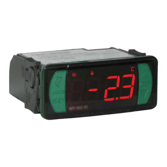
4. INDICATIONS AND KEYS
3
4
5
2
1
e
MT-512
2HP
Set Key
1
User-friendly Menu Key
2
Cooling indication LED
3
Heating indication LED
4
Defrost indication LED
5
Functions lockdown indication LED
6
Control functions OFF indication LED
7
Temperature unit indication LED
8
Upper Key
9
Lower Key
10
5. INSTALLATION - ASSEMBLING AND ELECTRICAL CONNECTIONS
Panel
(Side View)
ATTENTION
FOR INSTALLATIONS WHERE A SEALING IS REQUIRED TO AVOID LIQUID CONTACT,
THE CUT FOR THE CONTROLLER MUST BE OF 70,5X29mm MAXIMUM. THE SIDE
LOCKS MUST BE FIXED SO IT PRESSES THE RUBBER SEALING AVOIDING
INFILTRATION BETWEEN THE CUT AND THE CONTROLLER.
e
MT-512
DIGITAL CONTROLLER AND INDICATOR FOR
HEATING OR COOLING WITH NATURAL
DEFROST THROUGH COMPRESSOR SHUTDOWN
Manual
Functions
Control functions
defrost
lockdown
shutdown
e
2HP has tamper-proof
6
7
8
*SB 59 ( -50ºC to 200ºC / -58ºF to 392ºF)
* Optional - see chapter 8
71
± 0,5
mm
Dimension of the clipping
for fixing of the instrument
in panel
Panel (Front View)
2HP
IP 65
FRONT
Serial
Protection
programming
level
6. OPERATIONS
6.1 Quick Access Menu Map
By pressing ; it is possible to navigate through the function menus. For more details, see chapter 6.3.
See the functions map below:
FORCED DEFROST
;
MT-512
FUNCTIONS LOCKDOWN
;
MT-512
CONTROL FUNCTIONS
SHUTDOWN
;
MT-512
ADJUSTING THE DESIRED
TEMPERATURE (SETPOINT)
;
MT-512
MAX. AND MIN. TEMPERATURE
RECORD
;
9
MT-512
6.2 QUICK ACCESS KEYS MAP
10
When the controller is on temperature display mode, the following keys serve as a shortcut for the
following functions:
/ <
Pressed for 2 seconds: Setpoint adjustment.
Quick touch: Current process display.
<
Quick touch: Maximum and minimum temperatures display.
< <
Enters function selection.
6.3 BASIC OPERATIONS
6.3.1 Adjusting the desired temperature (setpoint)
/
Press key
for 2 seconds until the [SET,] message appears. When releasing the key, the adjusted
control temperature will appear.
<
>
Use keys
or
to change the value, and when ready, press
The desired temperature can also be changed through the quick access menu (see map in chapter 6.1)
or through Function [,F02] chapter 6.4.
Connection 115 Vac
POWER
REFR
5 6 7 8
SUPPLY
HEAT
9
10 11 12 13 14 15 16 17
1
2 3 4
SENSOR
Connection 230 Vac
POWER
REFR
5 6 7 8
SUPPLY
HEAT
9
10 11 12 13 14 15 16 17
1
2 3 4
SENSOR
EXIT FUNCTION
;
e
2HP
FUNCTION SELECTION
;
e
2HP
SHOW CURRENT PROCESS
;
e
2HP
ERASE MAX. AND MIN. VALUES
;
e
2HP
e
2HP
/
Connection 12 Vac/dc
16(12)A 2HP
POWER
5 6 7 8
SUPPLY
9
1
2 3 4
SENSOR
115 Vac
Load supply
Connection 24 Vac/dc
16(12)A 2HP
POWER
5 6 7 8
SUPPLY
9
1
2 3 4
SENSOR
230 Vac
Load supply
evolution
e
MT-512
2HP
e
MT-512
2HP
e
MT-512
2HP
e
MT-512
2HP
to record.
16(12)A 2HP
REFR
HEAT
10 11 12 13 14 15 16 17
12 Vac/dc
Load supply
16(12)A 2HP
REFR
HEAT
10 11 12 13 14 15 16 17
24 Vac/dc
Load supply
Advertisement

Related Manuals for Full Gauge Controls MT-512 E 2HP


Summary of Contents for Full Gauge Controls MT-512 E 2HP
- Page 1 • Industrial heating / Cooling equipment • Any other type of equipment requiring precise temperature control 3. TECHNICAL SPECIFICATIONS - Power supply: MT-512 E 2HP → 115 or 230 Vac ±10%(50/60 Hz) MT-512 MT-512 MT-512 EL 2HP → 12 or 24 Vac/dc ±10%...
- Page 2 6.5 PARAMETERS TABLE 6.3.2 Forced Defrost Forced defrost is carried out through the quick access menu. Press the key (quick touch) until the CELSIUS FAHRENHEIT message [defr] appears (flashing @LED), then press key (quick touch) to select. Then, the Description Max Unit Max Unit Standard...
- Page 3 8.3 Extended Frame F15 - Additional time at the end of the first cycle: The extended frame of Full Gauge Controls allows the installation of controllers of the Evolution and Ri lines with measures of 76 x 34 x 77 mm in varied situations, since it eliminates precision in the cutting to It serves to increase the cooling time only the first refrigeration cycle, increasing the efficiency there of.
- Page 4 USE OF WARRANTY To make use of the warranty, customers must send the properly packaged product to Full Gauge Controls together with the invoice or receipt for the corresponding purchase. As much information as possible in relation to the issue detected must be sent to facilitate analysis, testing and execution of the service.
Need help?
Do you have a question about the MT-512 E 2HP and is the answer not in the manual?
Questions and answers