Table of Contents
Advertisement
Quick Links
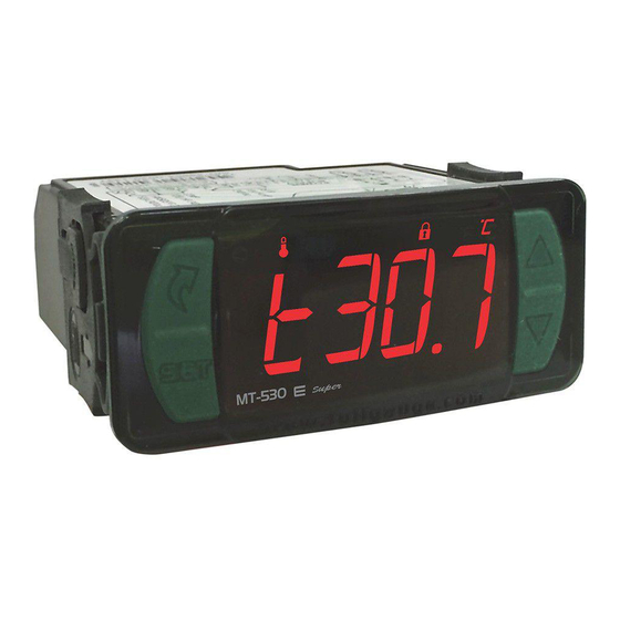
1. DESCRIPTION
e
MT-530
%uper has three outputs: one for temperature control, one for humidity control and a
The
third auxiliary output that acts as a second stage temperature control, humidity control, alarm or timer
cyclical.
This controller is indicated for low and medium relative humidity (10-85% non-condensing). Its
temperature sensors and humidity are united in a single bulb, reducing installation space and wiring. It
also includes an audible alarm (buzzer) and an intelligent system locking functions, preventing
unauthorized people from changing the control parameters.
The instrument features a serial communication for connection to Sitrad
Product complies with UL Inc. (United States and Canada).
2. APPLICATION
• Humidifiers / dehumidifiers
• Grains drying
• Laboratories
• Surgical rooms
• Climatized cellars
• Information technology centers
*For high percentage of humidity in the presence of water condensation, use the model AHC-80 Ri
plus.
3. TECHNICAL SPECIFICATIONS
- Power Supply: MT-530E Super 115 or 230 Vac ±10%(50/60 Hz)
→
MT-530EL Super 12 or 24 Vac/dc ±10%
→
- Control Temperature: -10 to 70.0 ºC ±1.5°C (with resolution of 0.1°C)
14 to 158 ºF ±3°F (with resolution of 1°F)
- Operation temperature: 0 to 50°C
32 to 122°F
- Control Humidity: 10 to 85%RH ±5%RH (with resolution of 0.1%RH)
- Operation humidity: 10 to 85% RH (without condensation)
- Load current: Therm : 16(8)A/250Vac 1HP
Humid : 5(3)A/250Vac 1/8HP
Aux : 5(3)A/250Vac 1/8HP
- Dimensions: 76 x 34 x 77 mm
(WxHxD)
- Dimensions of the clipping for fixing of the instrument: 71 ± 0,5 x 29 ± 0,5 mm (see item 5)
4. INDICATIONS AND KEYS
3
4
5
2
1
MT-530
%uper
Key Set
1
Menu key facility
2
Therm output led indicator
3
Humidity output led indicator
4
Aux output led indicator
5
Buzzer output led indicator
6
Lock functions led indicator
7
Temperature unit led indicator
8
Upper key
9
Lower key
10
5. INSTALLATION - ELECTRICAL CONNECTIONS AND PANEL
Panel
(Side View)
IMPORTANT
THE USE OF APPROPRIATE TOOLS IS ESSENTIAL TO AVOID DAMAGE IN THE
CONNECTION AT INSTRUMENT TERMINALS:
SCREWDRIVER SLOT 3/32''(2.4mm) FOR ADJUSTMENTS IN THE SIGNAL TERMINALS;
SCREWDRIVER PHILLIPS #1 FOR ADJUSTMENTS IN THE POWER TERMINALS;
e
MT-530
%uper
DIGITAL CONTROLLER AND INDICATOR
OF TEMPERATURE AND HUMIDITY
WITH SERIAL COMMUNICATION TO SITRAD
IP 65
FRONT
Functions
Buzzer
Protection
lockdown
level
supervisor
®
.
6
7
8
Connection 115 Vac
RS - 485
71
± 0,5
mm
5 6 7 8
1
2 3 4
Dimension of the clipping
for setting of the
instrument in panel
Panel (Front View)
ATTENTION
FOR INSTALLATIONS WHERE A SEALING IS REQUIRED TO AVOID LIQUID CONTACT, THE CUT FOR THE
CONTROLLER MUST BE OF 70,5X29mm MAXIMUM. THE SIDE LOCKS MUST BE FIXED SO IT PRESSES
THE RUBBER SEALING AVOIDING INFILTRATION BETWEEN THE CUT AND THE CONTROLLER.
System
6. OPERATIONS
6.1 Facilitated menu map
By pressing the button
below:
SETPOINT OUTPUT THERM
;
MT-530
%uper
SETPOINT OUTPUT HUMID
;
MT-530
%uper
SETPOINT OUTPUT AUX*
;
MT-530
%uper
INHIBITOR BUZZER*
;
MT-530
%uper
LOCK FUNCTION
;
MT-530
%uper
CONTROL FUNCTIONS
SHUTDOWN
;
MT-530
%uper
* These parameters are displayed when necessary.
6.2 FACILITATED KEY MAP
When the controller is on display temperature, the following shortcut keys are used for the following
functions:
9
/ <
Press 2 sec: Adjust setpoint.
Short press: Switch display of temperature or humidity for 4s.
<
10
Press 2 sec: When the buzzer is active inhibits the alarm.
<
Short press: Display of records minimum and maximum measures.
<
Press 2 sec: When the record is displayed, clear the history.
< <
Enter the function selection.
6.3 BASIC OPERATIONS
6.3.1 Adjusting the
To enter the setup menu press the setpoints
the display then the value of the setpoint output Therm adjustment. Use
value and confirm by pressing
of setpoint output Humid. Again use the
If the operating mode for the Aux output require setting a setpoint the message "[SP3,]" will appear
and it can be adjusted the same way is the previous ones. At the end the message "[----]
appear
indicating setup completion. The setpoints can also be adjusted individually on the facilitated
menu.
A B
POWER
SUPPLY
9
10 11 12 13 14 15 16 17
e
e
%u per
%u per
M T- 53 0
M T- 53 0
;
, it is possible to navigate through the function menus. See the map functions
EXIT THE MENU
SELECTION FUNCTION
ALTERNATE VIEWING MEASURE
CLEAR VALUES MAX. AND MÍN.
REGISTRATION OF
TEMPERATURE MÍN. AND MÁX.
desired
temperature and humidity (setpoint)
/
for 2 seconds. The message "[Sp1,]" will appear on
/
.Then the message "[SP2,]" will appear indicating the adjustment
<
>
and
keys to modify the value and confirm by pressing
Connection 230 Vac
RS - 485
A B
POWER
5 6 7 8
SUPPLY
9
10 11 12 13 14 15 16 17
1
2 3 4
evolution
E251415
;
MT-530
%uper
;
MT-530
%uper
;
MT-530
%uper
;
MT-530
%uper
;
MT-530
%uper
<
>
and
keys to modify the
/
.
" will
LEGEND
Yellow
Green
1
3
Orange/Brown
Red
2
4
Advertisement
Table of Contents

Subscribe to Our Youtube Channel
Related Manuals for Full Gauge Controls MT-530E Super


Summary of Contents for Full Gauge Controls MT-530E Super
- Page 1 %uper 3. TECHNICAL SPECIFICATIONS INHIBITOR BUZZER* ALTERNATE VIEWING MEASURE - Power Supply: MT-530E Super 115 or 230 Vac ±10%(50/60 Hz) → MT-530EL Super 12 or 24 Vac/dc ±10% → - Control Temperature: -10 to 70.0 ºC ±1.5°C (with resolution of 0.1°C) 14 to 158 ºF ±3°F (with resolution of 1°F)
- Page 2 Connection 12 Vac/dc Connection Vac/dc RS - 485 RS - 485 POWER POWER 5 6 7 8 5 6 7 8 SUPPLY SUPPLY 10 11 12 13 14 15 16 17 10 11 12 13 14 15 16 17 2 3 4 2 3 4 Loads supply Loads supply...
- Page 3 [,F28] Acting point of Buzzer by low temperature -10.0 70.0 °C -10.0 °F [,F29] Acting point of Buzzer by high temperature -10.0 70.0 °C 70.0 °F [,F30] Acting point of Buzzer by low humidity [,F31] Acting point of Buzzer by high humidity [,F32] Maximum time of the activated THERM output to activate the alarm min.
- Page 4 9.2 Extension Frame responsible manner of dispose its devices. In case of any doubts, contact Full Gauge The Full Gauge Controls extension frame allows the installation of Evolution / Ri line with measures controls for assistance. 76x34x77 mm (dimensions of the clipping for fixing in the extension frame is 71x29mm) in varied situations, since it eliminates precision cut to embed the instrument.
Need help?
Do you have a question about the MT-530E Super and is the answer not in the manual?
Questions and answers