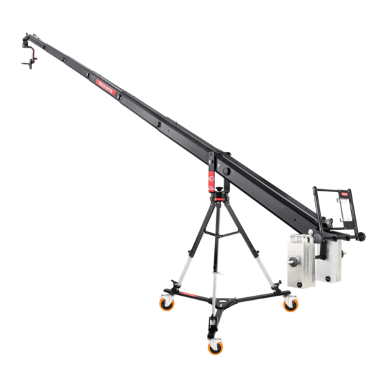
PROAIM Kite-22 Assembly Manual
Crane popular package
Hide thumbs
Also See for Kite-22:
- Assembly manual (32 pages) ,
- Instruction manual (22 pages) ,
- Setup and operational manual (16 pages)
Table of Contents
Advertisement
Quick Links
What's In The Box
Please inspect the contents of your shipped package to ensure you have received everything that is listed
below.
•
22ft Long Telescopic Camera Jib Crane
•
150mm Bowl Jib Stand with Spreader (LW-150)
•
D-33 Pro Camera Dolly
•
Sr. Pan Tilt Head with Accessories (PT-SR)
•
Zoom Control (P-ZC-3DV)
•
Customized Storage cases for Camera Jib Arm, Jib Stand & Accessories
•
Complimentary
Tools and Tool Pouch/Wrap
No part of this document may be reproduced, stored in a retrieval system, or transmitted by any form or by any means,
electronic, mechanical, photo-copying, recording, or otherwise, except as may be expressly permitted by the applicable copyright
Kite-22 Crane Popular Package (KITE-22-POPULAR)
A s s e m b l y M a n u a l
All rights reserved.
statutes or in writing by the Publisher.
1
Advertisement
Table of Contents

Related Manuals for PROAIM Kite-22


Summary of Contents for PROAIM Kite-22
- Page 1 Kite-22 Crane Popular Package (KITE-22-POPULAR) A s s e m b l y M a n u a l What’s In The Box Please inspect the contents of your shipped package to ensure you have received everything that is listed below.
- Page 2 First Packing • Jib Sections Second Packing • Jib Sections Third Packing • Accessories of Jib Crane Fourth Packing • Gravity Jib Stand Fifth Packing • Dolly Pack Sixth Packing • Sr Pan-tilt Head NOTE: We send the Jib sections in two boxes. One box has the sections with pipe packing, and the other cardboard box has the rest.
- Page 3 Packaging Material of Box 3: Accessories of Jib Crane Head Platform with Bolt, Shaft Collars, Washers and Nut Hub Section Joystick Controller Bracket Levelling Cable 6 x Shanks for Joining Arms 2 x pins Shank Hub Mounting Turn buckle knob 6 x Pins for Joining jibs 7 x Black Velcro Complimentary...
- Page 4 Packaging Material of Box 4: Gravity Stand Ultimate Gravity Stand Bowl 13mm Spanner 19mm Spanner (P-RB-SP) Spreader Stopper Gravity Stand Packaging Material of Carton Box 5: Camera Dolly D-33 Pro Camera Dolly 3 x Tripod holder 1 x 3/16” L-Type Allen Key 17mm Spanner...
- Page 5 Packaging Material of Box 6: Sr. Pan and Tilt Head with Accessories (PT-SR) AC Adapter Joystick Controller with cap Universal Adapter Accessories Sr. Pan-Tilt Head Cable and XLR Cable 1/4” Camera Fasteners Mounting Screw...
- Page 6 Safety Hints ATTENTION: PLEASE READ THE FOLLOWING CAUTIONARY POINTS BEFORE USING THE JIB TO PREVENT DAMAGE TO THE EQUIPMENT AND THE OPERATOR! • The crane may not be assembled or operated under the influence of alcohol, drugs, or any other intox- icating substances.
-
Page 7: Table Of Contents
INDEX Sr. No Particulars Page No. D-33 Dolly Assembly Tripod Holder Assembly LW-150 Jib Stand Assembly 9-11 Hub Mounting 11-12 Jib Section Assembly 12-14 Section 7 & Section 6 Assembly 14-15 Head Platform Mounting 15-16 Turn Buckle Mounting Levelling Cable Assembling 16-17 Joystick Controller Bracket Assembly Weight Rod Assembly... -
Page 8: D-33 Dolly Assembly
Kite-22 Crane Popular Setup Kite-22 Crane Popular mounting on Dolly D-33 Dolly Assembly • Loosen the side bolt of the D-33 Pro Camera Dolly using the 17mm spanner. NOTE: This dolly has various holes for flexible Tripod mounting. • Remove the Bolt nut, washer and Bolt. -
Page 9: Tripod Holder Assembly
• Tighten the Bolt nut using the 17mm spanner. • Repeat the same step to re-insert the second side Bolt. NOTE: The centre bolt will not be removed to open the D-33 Dolly. Tripod Holders Assembly • Remove the Allen bolt from the Tripod holder using a 3/16”... - Page 10 • Loosen the knob and extend the Tripod leg. • Now, lock it using the locking pin once it is at the desired length. • Tighten the knob. • Repeat the same step for extending the remaining Tripod legs. • Loosen the knob of the tripod holder and mount the Tripod Stand on the Dolly.
-
Page 11: Hub Mounting
• Remove the bolt on the base of the Tripod using the 21mm spanner. • Repeat the same step to remove the second bolt. Hub Mounting Assembly • Mount the Hub Mounting on the Tripod. NOTE: The Hub Assembly has several mounting holes for attaching additional accessories like a LCD Monitor or a Joystick box. -
Page 12: Jib Section Assembly
• Loosen the nut bolt using the 21mm spanner and remove the Hub mounting shank. Jib Section Assembly • Insert the 2nd section into the 1st section and mount them on the Hub mounting by aligning the threads. • Insert Shank into the Hub mounting ensuring the holes of the both sections are aligned with the holes of the Hub mounting. - Page 13 • Now, insert the Shank into second hole of the 1st Jib section, as shown in the image. • Re-insert the plastic washer and knob from the other side. • Tighten the knob using the 4mm T-Type Allen key. • Insert 3rd section into the 2nd section by ensuring the holes are aligned.
-
Page 14: Section 7 & Section 6 Assembly
• Tighten the shank knob using the 4mm T-Type Allen key. • Insert the locking pin into the 1st section from the top and lock it securely. • Similarly, insert the locking pin into the 2nd section from the top and lock it securely. •... -
Page 15: Head Platform Mounting
• Insert plastic washer and knob from the other side and tighten the knob securely. • 7th section is securely attached. • Insert locking pin into the 6th section from the top and lock it securely. • Attach 6th section with 5th, 5th section with 4th, 4th section with 3rd, 3rd section with 2nd and 2nd section with the 1st. -
Page 16: Turn Buckle Mounting
• Insert two Shaft collars inside the jib and insert plastic washer in the center of Jib and Head platform. • Insert plastic washer and steel washer to the other side of the long bolt. • After inserting washer, insert nut and tighten it using a 21mm spanner. -
Page 17: Joystick Controller Bracket Assembly
• Insert the other end of the Leveling cable into the Turn Buckle and lock the cable. • Stretch levelling cable your requirement. Joystick Controller Bracket Assembly • Attach the Joystick Controller Bracket to the Jib and insert the Shank. •... -
Page 18: Weight Rod Assembly
Weight Rod Assembly • Insert the Weight rod into Joystick Controller Bracket. • Now, insert the black tube to the center. • Using the same step insert the black tubes to the weight rod on both sides, as shown in the image. - Page 19 • The Jib is securely mounted on the Jib stand. Kite-22 Crane Starter mounting on Dolly...
- Page 20 Parts of Sr. Pan-Tilt Head Gear for Tilting Movement Motor For Tilting Movement Adjustable Camera Platform Gear for Panning Movement Motor For Panning Movement Base Platform for Tripod/ Jib Mounting...
-
Page 21: Sr. Pan-Tilt Head Mounting
Sr. Pan Tilt Head Mounting • Attach Sr. Pan-tilt Head to the Head Platform and insert the bolt. • Now, insert the fastener and secure it. • Sr. Pan-tilt Head is securely attached to the Head Platform. Camera Mounting • Mount the Camera (Not Included) on the... -
Page 22: 12V-Joystick Controller Assembly
• To set the position of the Camera plate, loosen or tighten its bolt using the 3/16" Allen key. • The camera is securely mounted. 12V-Joystick Controller Assembly • Remove Velcro from the top and bottom of the Joystick controller Bracket. •... -
Page 23: Cable & Xlr Cable Assembly
• Adjust the position of the Joystick controller at 90°. Cable & XLR Cable Assembly • Connect the female end of the Pan-tilt cable to the male end of the XLR cable. • Attach the cable's female end to the Joystick controller. - Page 24 • Attach the Power cable's other end to the Universal adapter. Parts of Joystick Controller Fuse Holder 4-Pin XLR 4-Pin Power P a n Speed Knob On/Off Switch Tilt Speed Knob Pan Damping Tilt Damping Pan Direction Tilt D irection Joystick for Pan/Tilt Direction...
-
Page 25: Screen Mounting
• Speed Controller adjusts the pan/tilt speed based on the requirement of the shot. • Damping control prevents the Head from stopping with a jerk enabling you to achieve smooth endings. • You can reverse the pan & tilt direction per your requirement. -
Page 26: Spin-3 Joystick Controller Mounting
• After mounting the screen use a screwdriver (Not Included) to tighten its bolt. • Loosen or tighten the bolt using a 4mm Allen key to adjust the positioning of the screen. Spin-3 Joystick Controller Mounting (Optional) • Remove all the bolts using a screwdriver. •... - Page 27 • Insert the bolt after aligning the holes and then tighten it using a screwdriver. • Repeat the same step to insert the remaining bolts. • Attach the Spin-3 Joystick controller and lock it securely. • Speed Controller The Speed Controller adjusts the speed of pan tilt &...
-
Page 28: Shorting The Length Of Jib
Parts of Spin-3 X Joystick Controller Fuse Holder 4-Pin Power 4-Pin XLR Dead Spot Pan-Tilt Roll Damping Control Speed Pan-Tilt Roll On/Off Switch Direction Joystick Shorting the Length of Jib • To shorten the length of the Kite crane remove the Levelling cable from the Shank of the Hub section. - Page 29 • Remove both locking pins from the 1st Section. • Loosen and remove the knob of the shank using a 4mm T-Type Allen key. • Now, remove the shank. • Remove the nut bolt of the Hub section's shank using the 21mm spanner and remove the shank, as shown in the image.
- Page 30 • Slide 3rd section into 2nd section and repeat the same step to insert the shank. NOTE: Make sure to align the holes of both sections. • 2nd Section is now securely attached to 3rd section . • Repeat the same steps to insert Shank with knobs and locking pins.
- Page 31 Different Shooting lengths 24.5 ft 22.3 ft 19 ft 15.10 ft 12.8 ft...
-
Page 32: Balancing
Balancing Follow these steps to balance the head:- • Find the horizontal balance point of your camera while holding the handle. • Mark this point on the side of the camera with chalk or tape. • Turn the unit on and move the tilt control until the camera plate is vertical. •... - Page 33 PROAIM Sr. PAN TILT HEAD The PROAIM™ Sr. PAN TILT HEAD circuitry is built entirely into joystick box. The only other requirement is the AC power pack (provided) or battery power. The power pack can handle 90-240 volts. Users will need the appropriate plug adapter for local use.
- Page 34 TILT DIRECTION SWITCH When the head shifts from a Jib to a tripod or vice versa, it needs a reversal of direction as the location of the head will be inverted. By switching “on” the tilt direction switch, we can immediately reverse the direction.
- Page 35 All joysticks are linear, meaning that each degree of movement of the stick correlates to the output. On the 12-volt PROAIM SR.PAN-TILT HEAD half deflection of the joystick indicates approximately 6 volts sent to the motors. But with the advent of Digital, we can now control the taper of the joystick, making it Logarithmic.
-
Page 36: Balancing Tips
Balancing Tips The sections collapse into each other 1. 24.5’ Jib Weights required for balancing only Jib (without camera & Pan Tilt) is: 55Kg (121.5 lbs) If the camera weight is 1kg, the jib is balanced with 55+5kg=60kg If the camera weight is 2kg the jib is balanced with 55+10kg=65kg 2. - Page 37 YOUR PROAIM KITE-22 CAMERA CRANE POPULAR PACKAGE ALL DRESSED UP AND READY TO GO! (SHOWN WITH OPTIONAL ACCESSORIES) Warranty: We offer one year warranty for our products from date of purchase. Within this period of time, we will repair it without charge for labor or parts. Warranty doesn’t cover transportation costs nor does it cover a product subjected to misuse or accidental damage.
Need help?
Do you have a question about the Kite-22 and is the answer not in the manual?
Questions and answers