
Subscribe to Our Youtube Channel
Related Manuals for ARB 3521090


Summary of Contents for ARB 3521090
- Page 1 L/CRUISER PRADO 150 SERIES (7 SEAT) COMPRESSOR BRACKET INSTALLATION GUIDE 3521090 Part No. 37801364 Revision Date 1/9/23 Copyright © 2023 by ARB Corporation Limited...
- Page 2 No liability is assumed for damages resulting in the use of the information contained herein. ARB Air Locker Air Operated Locking Differentials, ARB Air Locker Air Activation System and Air Locker are trademarks of ARB Corporation Limited. Other product names used herein are for identification purposes only and may be trademarks of their respective owners.
-
Page 3: Table Of Contents
Table of Contents Introduction Pre-Installation Preparation ................4 Description ......................4 Kit Contents ......................4 Tool-Kit Recommendations ................5 1.4.1 Tools ......................5 1.4.2 Supplies ......................5 Vehicle Preparation ..................... 6 Configuring a CKMTA12/24 Compressor Orientating the Compressor Outlet for Best Fit ..........8 Installation of Main Compressor Bracket Attaching the Compressor to the Bracket ............ -
Page 4: Introduction
Although your ARB Air Compressor Bracket comes complete with all the step by step instructions you will need to install it, ARB recommends that you have your ARB Air Compressor installed by a trained professional. Many ARB distributors around the world have been fully instructed in Air Compressor installations by ARB, and have gained a wealth of experience and skill from years of performing similar installations. -
Page 5: Tool-Kit Recommendations
Torque wrench with 5 – 100 Nm range A razor knife to cut the carpet (if fitting Air Locker lines through the OE plug in the floor) A leak test gauge (i.e., ARB# ALTG01). A multimeter A soldering iron 1.4.2... -
Page 6: Vehicle Preparation
Introduction 1.5 Vehicle Preparation A manufacturer’s service manual and optional ARB Operation & Installation manuals should be used in conjunction with these instructions. Remove scuff panels from LHS rear door. SCUFF PANELS 3RD ROW SEATS REAR LOWER TRIM ... - Page 7 Introduction REAR LOWER TRIM AND 3 SEATS REMOVED Remove the bracket shown below using a 14 mm socket. REMOVE FASTENER USING 14 MM SOCKET Retain fastener and set the bracket aside.
-
Page 8: Configuring A Ckmta12/24 Compressor
Configuring a CKMTA12/24 Compressor 2 Configuring a CKMTA12/24 Compressor 2.1 Orientating the Compressor Outlet for Best Fit Refer to Section 2 of the installation guide (Part No 2102MTA12) supplied with the compressor for instructions on cover removal. NOTE: Sealant is not required for JIC fittings. ... - Page 9 Configuring a CKMTA12/24 Compressor Install the 90 degree JIC elbow (0740104) to the manifold cap. 0740104 90 DEG ELBOW JIC-4(F) to JIC-4(M) Install the 0.5 m hose (0740202) as shown. Tighten the elbow and hose fittings ensuring that the hose remains at 90 degrees to the manifold cap as shown. Use a spanner to prevent the elbow from rotating.
- Page 10 Configuring a CKMTA12/24 Compressor Pass the assembled hose and manifold cap through the compressor assembly as shown. Reattach the manifold cap to the compressor and tighten the manifold bolt to approximately 9 Nm (7 lbf.ft). ASSEMBLED HOSE ROUTED THROUGH COMPRESSOR ASSEMBLY ASSEMBLED HOSE ROUTED THROUGH COMPRESSOR...
-
Page 11: Installation Of Main Compressor Bracket
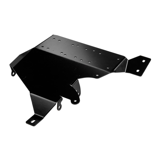
Installation of Main Compressor Bracket 3 Installation of Main Compressor Bracket 3.1 Attaching the Compressor to the Bracket Mount the compressor on the bracket as shown below. Use four sets of fasteners supplied with your compressor kit (bolt, spring washer, flat washer). NOTE: The main curvature of the bracket should be AWAY from the compressor. -
Page 12: Configuring The 4L Air Tank
Installation of Main Compressor Bracket 3.2 Configuring the 4L Air Tank Attach two 90 degree JIC elbows to the tank’s JIC adaptors as shown. THE COMPRESSOR HOSE ATTACHES TO THIS FITTING Attach the free end of the 0.5 m hose to the fitting shown above. - Page 13 Installation of Main Compressor Bracket NOTE: The pinch weld included in the kit can be used to avoid the tank from rubbing on the body panels. OPTIONAL PINCH WELD LOCATIONS Gently insert the tank into the space shown. This is easiest if the right side of the tank is inserted first towards the front of the vehicle.
- Page 14 Installation of Main Compressor Bracket FLEX PANEL OUTWARDS AND UPWARDS IF REQUIRED With the tank in position, check that the hose is not kinked or pinched.
-
Page 15: Attaching The Main Bracket To The Vehicle
Installation of Main Compressor Bracket 3.3 Attaching the Main Bracket to the Vehicle The four attachment points for compressor bracket are highlighted below. MOUNTING LOCATION FOR MOUNTING LOCATION FOR COMPRESSOR BRACKET COMPRESSOR BRACKET REMOVED BRACKET Fit the bracket into position, and loosely retain it with the fasteners listed below. NOTE: Do not tighten the fasteners at this stage. -
Page 16: Attaching The Air Tank To The Bracket
Installation of Main Compressor Bracket FASTENER AND BRACKET THAT WAS REMOVED IN PREVIOUS STEP REINSTALLED ON TOP OF COMPRESSOR BRACKET 3.4 Attaching the Air Tank to the Bracket Using the fasteners that came with your air tank kit, attach your tank to the bracket at the three points marked below. -
Page 17: Torquing Fasteners
Installation of Main Compressor Bracket 3.5 Torquing Fasteners Once the bracket and tank are in a satisfactory position, torque the M6 fasteners to 9Nm (7 lbf.ft) and torque the OE fastener to 25Nm (18 lbf.ft). TORQUE 3 X BRACKET FASTENERS 9 Nm [7 lbf.ft] TORQUE 3 X M6 AIR TANK... -
Page 18: Configuration Of The Air Locker Manifold Kit
Installation of Main Compressor Bracket COMPRESSOR 2-3 MM CLEARANCE BETWEEN BODY BRACKET AND COMPRESSOR BODY BRACKET 3.6 Configuration of the Air Locker Manifold Kit NOTE: Newer versions of the manifold kit use parallel NPSC fittings instead of the tapered NPT fittings. The O-ring versions of the fittings do not require thread sealant. - Page 19 Installation of Main Compressor Bracket Attach the hose from the manifold kit to the tank outlet. Mount the manifold assembly to the compressor bracket as shown using the fasteners supplied with the manifold kit (bolt, nyloc nut). Take note of the manifold bracket direction in the picture below.
-
Page 20: Installation Of Switch Panel To Interior Trim
Installation of Switch Panel to Interior Trim 4 Installation of Switch Panel to Interior Trim 4.1 Installation of the Switch Panel to Interior Trim The image below shows the layout for the panel switch plate. The switch plate is mounted inside the storage pocket found on the trim panel removed earlier in the installation process. - Page 21 Installation of Switch Panel to Interior Trim 29 MM DIA HOLE FOR OPTIONAL POWER OUTLET DRILL 6.5 MM DRILL 6.5 MM MOUNTING HOLE MOUNTING HOLE RECTANGULAR CUTOUT FOR COMPRESSOR SWITCH 19 MM HOLE FOR QUICK CONNECT COUPLING DRILL 6.5 MM DRILL 6.5 MM MOUNTING HOLE MOUNTING HOLE...
- Page 22 Installation of Switch Panel to Interior Trim Secure the switch plate to the trim panel using 4 x M6 x 16 button head screws, 4 x M6 x 16 x 1.2 washers, and M6 Nyloc nuts. 1 X M6 X 16 BUTTON HEAD SRCEW 1 X M6 X 16 BUTTON HEAD SRCEW 1 X M6 X 16 X 1.2 MM WASHER 1 X M6 X 16 X 1.2 MM WASHER...
-
Page 23: Completing The Installation
Completing the Installation 5 Completing the Installation 5.1 Connecting Hoses Connect a hose (0740202 hose reinforced JIC-4 0.5 M) from the free port on the manifold to the quick connect coupling as shown. Route the hose as shown below to allow easy fitment of the trim panel and tighten the fittings using a 14 mm spanner. -
Page 24: Post-Installation Check List
Completing the Installation 5.5 Post-Installation Check List Now that the compressor installation has been completed, ARB recommends that you take the time to complete the following check list to ensure that you have not missed any vital steps. Air system leak test completed.
Need help?
Do you have a question about the 3521090 and is the answer not in the manual?
Questions and answers