
Subscribe to Our Youtube Channel
Related Manuals for ARB 3540320


Summary of Contents for ARB 3540320
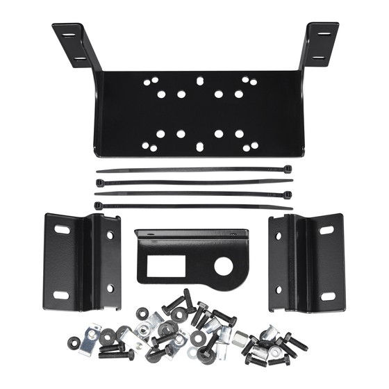
- Page 1 FORD RANGER DUAL CAB SINGLE COMPRESSOR BRACKET (SUITS PX, PX2, PX3 & USA 19ON MODELS) INSTALLATION GUIDE 3540320 Fitting Instruction No. 3781961 Revision Date 01/04/2020 Copyright © 2020 by ARB Corporation Limited...
- Page 2 No liability is assumed for damages resulting in the use of the information contained herein. ARB Air Locker Air Operated Locking Differentials, ARB Air Locker Air Activation System and Air Locker are trademarks of ARB Corporation Limited. Other product names used herein are for identification purposes only and may be trademarks of their respective owners.
-
Page 3: Table Of Contents
Table of Contents Introduction 1.1 Pre-Installation Preparation ..................4 1.2 Description ........................4 1.3 Kit Contents ........................4 1.4 Tool-Kit Recommendations ..................5 1.4.1 Tools ......................... 5 1.4.2 Supplies ........................5 Vehicle Preparation 2.1 Trim Removal......................... 6 2.2 Switch & Chuck Bracket Install ................7 2.3 Bracket Kit Preparation.................... -
Page 4: Introduction
Although your ARB Air Compressor Bracket comes complete with all the step by step instructions you will need to install it, ARB recommends that you have your ARB Air Compressor installed by a trained professional. Many ARB distributors around the world have been fully instructed in Air Compressor installations by ARB, and have gained a wealth of experience and skill from years of performing similar installations. -
Page 5: Tool-Kit Recommendations
Allen keys; 3mm (CKSA), 4mm (CKMA), for adjusting compressor body mount. Screwdrivers; No.2 Phillips & Small flat Torque Wrench 5 to 100Nm range A leak test gauge (i.e., ARB# ALTG01). A multimeter A soldering iron. 1.4.2 Supplies ... -
Page 6: Vehicle Preparation
Vehicle Preparation 2.1 Trim Removal A manufacturer’s service manual and optional ARB operation & Installation manuals should be used in conjunction with these instructions. NOTE: Sections 2.1 & 2.2 only required if fitting the switch & air chuck bracket to the B-pillar trim ... -
Page 7: Switch & Chuck Bracket Install
Vehicle Preparation Unclip the B-pillar LH side lower plastic trim and carefully remove trim from vehicle. 2.2 Switch & Chuck Bracket Install Lay the trim down and position the bracket as shown. Mark the mount holes with a permanent marker. - Page 8 Vehicle Preparation Drill out the mount holes to 7mm. Mount the bracket as shown using 2x M6x20 bolts, M6 flat washers & M6 flange nuts. You may be required to cut a small section of plastic ribbing out to allow clearance for the washer and nut.
-
Page 9: Bracket Kit Preparation
Vehicle Preparation Reinstall the plastic trim. Bracket should be positioned as shown. Reinstall door jamb seal and scuff plate. 2.3 Bracket Kit Preparation Fit the U-nuts to the 3752900 bracket mount feet as shown. Loosely mount the feet to the compressor bracket using M6x20 bolts & M6 flat washers as shown. -
Page 10: Bracket Kit Install
3 Bracket Kit Install 3.1 Nutsert Install Sit the bracket assembly in desired position and mark the centre of the slotted holes with a permanent marker. (PX3 shown). Drill out the floor with a 10mm drill bit. Drill through both the carpet and the steel floor. - Page 11 3 Bracket Kit Install If using the supplied nutsert tool, hold the lower machined nut with a 12mm spanner. Tighten the M6 bolt with a 10mm socket & ratchet or using an impact driver as shown. Tighten until you can feel a significant increase of resistance on the bolt. Remove the bolt from the nutsert and repeat for the other 3 nutserts.
-
Page 12: Bracket Feet Install
3 Bracket Kit Install 3.2 Bracket Feet Install The floor should now look like the above LH image. Remove the mounting feet from the bracket assembly used for marking hole positions. Install the mounting feet as shown in the RH image above, using M6x20 bolts & M6 washers. -
Page 13: Compressor Install
4 Compressor Install 4.1.1 Orientation of compressor for best fit - CKMA Loosen the two allen head screws and rotate the compressor 90° in the bracket as shown. 8Nm [6 lbf.ft]. Tighten the allen head screws to Loosen the bolt holding the manifold using a 10mm spanner. Rotate the manifold 90° as 9Nm [7 lbf.ft]. -
Page 14: Mounting Compressor To Bracket
4 Compressor Install 4.2 Mounting compressor to bracket Mount the compressor to the bracket using the M6x16 screws and washers supplied with the bracket fitting kit as shown. Manifold and manifold outlets should face upwards. 9Nm [7 lbf.ft]. Tighten the M6 screws to MANIFOLD BOLT ... -
Page 15: Plumbing Up Compressor For Use With Air Chuck
4 Compressor Install 4.3 Plumbing up compressor for use with air chuck Below is an example of how to connect the compressor to the air chuck. Ensure that no part of the air hose or fittings are in contact with the interior panel behind, or that it touches the seat when closed. -
Page 16: Post-Installation Check List
4 Compressor Install Post-Installation Check List Now that the compressor installation has been completed, ARB recommends that you take the time to complete the following check list just to ensure that you haven’t missed any of the vital steps. ...
Need help?
Do you have a question about the 3540320 and is the answer not in the manual?
Questions and answers