Table of Contents
Advertisement
Advertisement
Table of Contents

Subscribe to Our Youtube Channel
Related Manuals for Technogym Skillmill


Summary of Contents for Technogym Skillmill
- Page 1 killmill Technical Service Guide Rev. 3.5 - (October 2018)
- Page 3 The information in this manual is intended for QUALIFIED TECHNICAL PERSONNEL, who have been specifically trained by Technogym S.p.A. and are qualified to carry out fine-tuning and start-up of the equipment, as well as major maintenance work and repairs, requiring in-depth understanding of the equipment, how it works, its safety devices and maintenance procedures.
- Page 4 Skillmill Technical Service Guide - Rev. 3.5 Blank page. Page 4 email: support@technogym.com...
-
Page 5: Table Of Contents
3 . 1 . 7 Angle sensor ........................35 3 . 1 . 8 NFC (Connect version) ...................... 37 3 . 1 . 9 Bluetooth Smart ....................... 37 3 . 1 . 10 Wi-Fi (Connect version) ....................38 3 . 2 technical characteristics - skillmill, European and USA version .. 38 email: support@technogym.com Page 5... - Page 6 Skillmill Technical Service Guide - Rev. 3.5 ACCESSORIES ......................... 41 MOVING AND INSTALLING THE EQUIPMENT ..........43 5 . 1 Installation specifications and requisites ......... 43 5 . 2 Lifting and moving the equipment ............44 TROUBLESHOOTING & CONFIGURATION ............45 6 . 1 Procedure for replacing components ........... 45 6 . 2 Executable SW for diagnostics with PC ..........46 6 .
- Page 7 (CONSOLE AND CONNECT) DISPLAY CONFIGURATION PROCEDURE THAT DOES NOT ACTIVATE THE KEY BACKLIGHTING ....62 6 . 5 . 2 Skillmill (CONNECT) DISPLAY CONFIGURATION procedure that activates the KEY backlighting ......................62 6 . 5 . 3 Combo list ........................... 63 6 . 6 TROUBLESHOOTING ................. 65 6 . 6 . 1 The display does not turn on (Connect version) ............
- Page 8 Skillmill Technical Service Guide - Rev. 3.5 6 . 7 . 2 Skillmill CONNECT calibration procedure that activates the backlighting of the KEYS ........................... 90 6 . 7 . 3 automatic correct calibration check ................91 6.7.3.1 what to do if a calibration error appears ..................... 93 6.7.3.1.1 value > ±10% of the standard value ........................93 6.7.3.1.2 value ≤ ±10% of the standard value ........................94 6 . 8 procedure for setting the date and time ..........94 6 .
- Page 9 Skillmill: Technical Service Guide - Rev. 3.5 7 . 16 snap ring on the inside and outside of the rh and lh belt pulleys, both on the front and rear shafts ............118 7 . 17 positioning the brake unit stop screw ..........119 ADJUSTMENTS AND REGULATIONS ..............121 8 . 1 ADJUSTMENT ..................... 121 8 . 2 regulation ....................121 SW UPDATE ..........................123 9 . 1 SW update procedure ................
- Page 10 Skillmill Technical Service Guide - Rev. 3.5 email: support@technogym.com Page 10...
-
Page 11: General Info
GENERAL INFO INTRODUCTION This document has been prepared specifically for Technogym Service, to provide authorised personnel with the information needed to carry out maintenance and repair work correctly. A thorough understanding of the technical data contained herein is fundamental to guarantee the complete professional training of the operator. -
Page 12: Tips
Technical Service Guide - Rev. 3.5 TIPS Technogym advises you to plan your technical assistance task in the following way: Carefully assess the information given by the customer regarding the operating faults, and ask the necessary questions to clarify how the problem shows itself. -
Page 13: Technical Specifications
Skillmill: Technical Service Guide - Rev. 3.5 TECHNICAL SPECIFICATIONS Technical specifications Console Connect Wiring type Cordless Cordless Cable Console 7” LCD display with Console type 7” FSTN display backlight Power supply Rechargeable battery LPS 5V mains supply Yes, via NFC (RFID), mywellness®... -
Page 14: Mechanical Characteristics
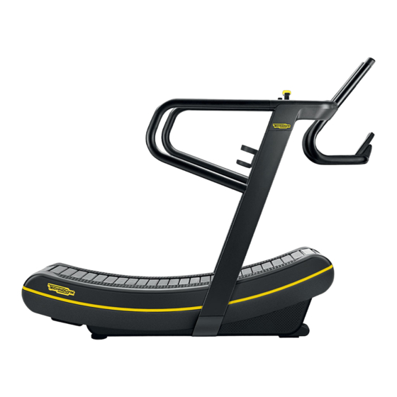
Skillmill Technical Service Guide - Rev. 3.5 MECHANICAL CHARACTERISTICS 2.2.2 OVERALL DIMENSIONS OF THE EQUIPMENT Skillmill LENGTH (L) 1910 mm - 75.2” WIDTH (W) 890 mm - 35” HEIGHT (H) 1540 mm - 60.6” WEIGHT (of the equipment) 180 kg - 397 lb... -
Page 15: Dimensions And Weight Of The Packaging
Italy: equipment assembled and bagged without cardboard; • Abroad: equipment disassembled and packaged in cardboard (for the assembly, refer to the distribution logistics course or the “Skillmill - Assembly instructions” document contained in the packaging). Packaging - Italy 2250 x 1030 x 1760 (mm) DIMENSIONS (L x W x H) 88.6 x 40.6 x 69.3 (inches) -
Page 16: Environmental Characteristics
Skillmill Technical Service Guide - Rev. 3.5 Packaging - abroad 2250 x 1030 x 800 (mm) DIMENSIONS (L x W x H) 88.6 x 40.6 x 31.5 (inches) WEIGHT 240 kg MAX - 529 lb MAX Table 4 Figure 3... -
Page 17: Compliance With Standards And Directives
Skillmill: Technical Service Guide - Rev. 3.5 COMPLIANCE WITH STANDARDS AND DIRECTIVES The equipment complies with the following standards and directives: • 2006/42/EC Machinery Directive • 2014/30/EU EMC Directive • 2014/53/EU R&TTE Directive EUROPEAN DIRECTIVES • 2011/65/EU RHOS 2 Directive •... -
Page 18: Equipment Coding
Skillmill Technical Service Guide - Rev. 3.5 EQUIPMENT CODING The Skillmill equipment code is a 16-character alphanumeric made up as follows: Characters Description Values and meaning 1, 2 Line Equipment K = Skillmill 0 = Standard Product version 1 = UL... -
Page 19: Serial Number Structure
The serial number is made up of alphanumeric characters as follows: Characters Description Values and meaning DJ = Line K = Skillmill 0 = Standard 1 = UL 1, 2, 3, 4, 5, 6 Type of product 3 = Powered... -
Page 20: Position Of Serial Number And Equipment Code Labels
POSITION OF SERIAL NUMBER AND EQUIPMENT CODE LABELS There are two labels indicating the serial number and equipment code: below the central handlebar on the frame, below the left side guard Technogym S.p.A. Via Calcinaro 2861, Cesena (FC) Made in Italy SKILLMILL Model No: DJK03D... -
Page 21: Wiring Diagrams
Skillmill: Technical Service Guide - Rev. 3.5 WIRING DIAGRAMS 2.8.2 WIRING DIAGRAM - CONNECT VERSION Complete ANGLE SENSOR RPM SENSOR CONSOLE NFC BOARD DISPLAY BOARD CU0863 CU0854 TOUCH KEYPAD Patch Patch +5.5V Patch connection connection BOARD TX and RX connection... -
Page 22: Wiring Diagram - Console Version
Skillmill Technical Service Guide - Rev. 3.5 2.8.3 WIRING DIAGRAM - CONSOLE VERSION Complete ANGLE SENSOR RPM SENSOR CONSOLE DISPLAY BOARD CU0863 TOUCH KEYPAD +5.5V Patch Patch BOARD connection connection TX and RX CU0867 CU0864 LOW KIT CPU BOARD CU0890 CU0866 +5.5V... -
Page 23: Cables
Skillmill: Technical Service Guide - Rev. 3.5 CABLES The colour of the cables may change: in particular, refer to the Pin Out. 2.9.2 CU CABLES CU0853: Cable A - Low Kit / CPU board (CPU board / patch connector) CPU board... - Page 24 Skillmill Technical Service Guide - Rev. 3.5 CU0863: Cable A - Angle sensor (Patch connector / angle sensor) Patch connector Signal Colour Angle sensor +3.3V DC Brown Angle White Green Table 12 CU0867: Cable B - Angle sensor (Patch connector / Low Kit)
- Page 25 Skillmill: Technical Service Guide - Rev. 3.5 CU0866: Cable A - Low Kit / CPU board (Low Kit / patch connector) Patch connector Signal Colour Low Kit +5V DC Black UI_TX Brown UI_RX White LKIT_RPM sensor Blue GND_Power Grey N.C. (GND) N.C.
- Page 26 Skillmill Technical Service Guide - Rev. 3.5 CU0889: 5V JACK cable (Battery/5V jack) Battery Signal Colour 5V jack (jack with cast ca- ble) +5V DC Black Table 19 CU0890: Low Kit / battery Low Kit Signal Colour Battery +5V DC...
-
Page 27: Operating Principle
Skillmill: Technical Service Guide - Rev. 3.5 OPERATING PRINCIPLE ELECTRONIC COMPONENTS 3.1.1 VOLTAGE CONVERTER (POWER SUPPLY UNIT) The voltage converter receives the high voltage and transforms it into low voltage (5V). It can supply a maximum current of 2A to power all the equipment electronics (display, angle sensor, RPM sensor and NFC). -
Page 28: Display (Connect Version)
Skillmill Technical Service Guide - Rev. 3.5 71.70 ± 0.5 1500 ± 50 10 ± 0.5 18.9 ± 0.4 100 ± 10 130(REF) Figure 7 - measurements in mm 3.1.2 DISPLAY (CONNECT VERSION) Display with the following characteristics: • WI-FI technology •... -
Page 29: Display (Console Version)
Skillmill: Technical Service Guide - Rev. 3.5 3.1.3 DISPLAY (CONSOLE VERSION) Compared with the Connect version display, the one on the Console version doesn't have the following features: Wi-Fi technology; display backlighting; key backlighting; heart button not illuminated but drawn. -
Page 30: Rpm Sensor
(completing a full turn of the pulley using a feeler gauge) is D=0.8mm (D=0.0315") For the Skillmill Console version, starting from SN DJK04D16000241 for the non-UL version and DJK14D16000003 for the UL version, the equipment has standard screws without magnets, where the distance between the RPM sensor and the screws is D=0.8mm (D=0.0315”). - Page 31 Skillmill: Technical Service Guide - Rev. 3.5 D=0,8mm D=0.0315” Figure 10 • if the pulley is equipped with magnets (magnetic washer under the screws), the distance between the RPM sensor and the nearest magnet (completing a full turn of the pulley using a feeler gauge) is D=0.8mm (D=0.0315")
-
Page 32: Battery (Console Version)
The battery is connected to the Low Kit, through which it supplies power to the various equipment components: the display, angle sensor and RPM sensor. WARNING: the Skillmill battery MUST NEVER be connected to USB cables other than the original, approved one on the machine itself. Risk of damage to the battery. - Page 33 Skillmill: Technical Service Guide - Rev. 3.5 Figure 13 If the recharge is made without disconnecting the battery from the machine, the battery will turn on automatically when the battery charger is connected and the battery button will be disabled. When the recharging procedure has ended, the battery will be automatically ON when the battery charger is disconnected. The battery can also be removed, to charge it in another place without moving the equipment. To do this: Do not press the battery button. If it is accidentally pressed, the effect will be as follows: Effect of the battery button (B): •...
- Page 34 Skillmill Technical Service Guide - Rev. 3.5 Let the battery charge for at least 16 hours. Figure 15 - steps 2-3-4 Disconnect the power supply unit from the battery. You can now test whether the battery is working properly: •...
-
Page 35: Angle Sensor
Skillmill: Technical Service Guide - Rev. 3.5 If the battery is working correctly, reconnect it to the two connectors on the product. Figure 17 Insert the battery in its seat and refit the front guard of the equipment. As already explained, if the recharge is made without disconnecting the battery from the machine, the battery will turn on automatically when the battery charger is connected and the battery button will be disabled. When the recharging procedure has ended, the battery will be automatically ON when the battery... - Page 36 Skillmill Technical Service Guide - Rev. 3.5 Figure 19 - right side of the internal part of the equipment The angle sensor is basically a potentiometer installed on the axis of the magnetic brake. It provides the Low Kit with the position of the brake (from 0 to 10).
-
Page 37: Nfc (Connect Version)
Skillmill: Technical Service Guide - Rev. 3.5 3.1.8 NFC (CONNECT VERSION) Figure 20 - left-hand handlebar of the equipment The user can log in to the equipment via the NFC board: TGS key, Mywellness Key and Smartphone NFC. 3.1.9 BLUETOOTH SMART The Bluetooth Smart chip enables the user to log in to the equipment using a Bluetooth Smart Smartphone and connect the Bluetooth Smart cardio belt. -
Page 38: Wi-Fi (Connect Version)
Display of the Skillmill class data in real time on the Mega screen/Monitor/TV. Display of the Skillmill class data in real time on the Mega screen/Monitor/TV: this function requires Unity Self with an HDMI output, starting from product E0202V15: UNITY SELF EXCITE HDMI and E0204V15 UNITY SELF ARTIS HDMI. - Page 39 Technical Service Guide - Rev. 3.5 Figure 22 SKILLMILL, AMERICAN VERSION: on the American version, the tread belt rotates in both directions, but movement is stopped if it rotates in the "wrong" direction (from the back part to the front).
- Page 40 Skillmill Technical Service Guide - Rev. 3.5 The movement is stopped by a system made up of a free wheel and a friction brake. This unit is positioned on the opposite side to the brake assembly. It doesn't entirely block the movement of the belt, but only allows rotation at very low speeds.
- Page 41 Skillmill: Technical Service Guide - Rev. 3.5 ACCESSORIES For details, refer to the marketing material. email: support@technogym.com Page 41...
- Page 42 Skillmill Technical Service Guide - Rev. 3.5 Blank page. Page 42 email: support@technogym.com...
- Page 43 Place the equipment on a flat surface where there are no vibrations and where the load- bearing capacity is sufficient for the weight to be supported (taking into consideration the weight of the user as well). Depending on the destination country, the equipment may be shipped partially dismantled, packed in cardboard packaging and fixed to a pallet or totally assembled in a transparent plastic wrapping and fixed to a wooden pallet. For the assembly, refer to the distribution logistics course or the “Skillmill - Assembly instructions” document contained in the packaging. The area must not be dusty or sandy. The temperature and humidity operating requisites indicated in paragraph “2.3 Environmental characteristics” must be respected. email: support@technogym.com...
- Page 44 Skillmill Technical Service Guide - Rev. 3.5 LIFTING AND MOVING THE EQUIPMENT The equipment has fixed front wheels. To move it, lift it slightly as shown in the figure, and push it forward or backward. Given the weight of the equipment, we recommend that more than one person be involved in this operation. WARNING: the equipment must be moved and positioned on the ground with ex- treme care, as it may become unstable. If the floor is unsuitable for the use of wheels, move the equipment with normal lifting and handling methods as shown in the distribution logistics installation video. Skillmill Figura 26 Page 44 email: support@technogym.com...
- Page 45 Calibrate the brake table. Remember that, from the SW version SKILLMILL CONNECT: High Kit: BA01.49 - wi-fi: CA01.16; SKILLMILL CONSOLE: High Kit: BA01.49, a function has been added at SW level to ensure a check of the correct calibration. For the details, refer to “6.7 Calibrating the brake table”. REPLACEMENT OF LOW KIT: IT is necessary to: Update the FW of the Low Kit and the console brake table, using the upgrade USB key (with PC Synch);...
- Page 46 (Skillmill Console version); Note that from the SW High Kit BA_1.43 version of the Skillmill Connect version, the default display is always on, even when no-one is using the equipment. The first time the PC is connected with Skillmill or New Group Cycle (D92) or MYRUN TECHNOGYM or MYCYCLING, it will ask you to install a driver for the detected device.
- Page 47 Skillmill: Technical Service Guide - Rev. 3.5 SELECT THE CORRECT SELECT BAUD RATE 19200 COM PORT COMMAND INPUT FIELD CHECK THE BOX +CR Figure 27 email: support@technogym.com Page 47...
- Page 48 Skillmill Technical Service Guide - Rev. 3.5 STRUCTURE FOR ENTERING COMMANDS The structure of the command/message is: @COMANDO [ARG1] [ARG2]# Character Compulsory Description Message start marker Command (the acceptable commands are described in the COMMAND YES following sections) ARG1 First topic of the command (if required by the command)
- Page 49 Skillmill: Technical Service Guide - Rev. 3.5 6.3.1.3 FIRMWARE VERSION (BETTER KEYPAD) Command Notes Command @KEYBFWVER# Prints the firmware version in the Better keypad. Table 26 6.3.1.4 FIRMWARE VERSION (LOW KIT) Command Notes Command @LOWKITFWVER# Prints the firmware version in the Low Kit. Table 27 6.3.1.5 LOW KIT BRAKING TABLE VERSION Command Notes Command @LOWKITTBVER# Prints the braking table version in the Low Kit.
- Page 50 Skillmill Technical Service Guide - Rev. 3.5 6.3.2.3 SETTING THE FACILITY URL Command Notes Command @SFACILITYURL fc# Sets the facility URL of the equipment. Table 31 The parameter fc indicates the name of the facility URL of the equipment. 6.3.2.4 VIEWING THE FACILITY URL...
- Page 51 Skillmill: Technical Service Guide - Rev. 3.5 6.3.3 WI-FI AND NETWORK CONFIGURATION Settings to be configured by the club. 6.3.3.1 SETTING A NAME FOR THE NETWORK Command Notes Sets the SSID of the access point that the console Command @SWIFISSID ssid# must connect to. Table 36 The parameter ssid indicates the name of the Wi-Fi network.
- Page 52 Skillmill Technical Service Guide - Rev. 3.5 6.3.3.4 CHECKING THE CONNECTION TYPE Command Notes Displays the SSID, password and type of Command @RWIFICONFIG# encryption used by the configured access point. Table 39 The parameter ssid indicates the name of the Wi-Fi network. 6.3.3.5 WRITING THE CONSOLE IP ADDRESS...
- Page 53 Skillmill: Technical Service Guide - Rev. 3.5 6.3.3.7 CHECKING THE IP ADDRESS - DEFAULT GATEWAY - NETMASK Command Notes Displays the IP address of the console, the default Gateway and the netmask the console Command @RNETPARAM# is currently using (regardless of whether these have been assigned in DHCP mode or have been configured as static).
- Page 54 Skillmill Technical Service Guide - Rev. 3.5 The parameter tsend indicates the data sending period to Unity Self (expressed in seconds). 6.3.4.3 DISPLAYING THE MONITOR CONFIGURATION Command Notes Command @RRTMCONFIG# Displays the Unity Self configuration. Table 46 6.3.4.4 ENABLING DATA SENDING Command Notes Command @ENABLERTM# Enables the sending of data to Unity Self.
- Page 55 Skillmill: Technical Service Guide - Rev. 3.5 6.3.5.2 SETTING THE DISPLAY TO OFF IN STANDBY Command Notes Configures the Connect equipment so the Command @SDISPLAYOFFSTANDBY# display is switched off in standby mode. Table 50 6.3.6 CONFIGURING TIME-OUT 6.3.6.1 SETTING TIME-OUT Command Notes Sets the time-out after which (when the speed...
- Page 56 Skillmill Technical Service Guide - Rev. 3.5 6.3.7 CONFIGURING THE SUMMARY 6.3.7.1 SETTING THE MINIMUM SPEED AND TIME TO INTERRUPT THE SUMMARY Command Notes Sets the minimum speed and the time for which Command @SNEWEXCOND speed time# it must be maintained in order to interrupt the summary by walking on the belt.
- Page 57 Skillmill: Technical Service Guide - Rev. 3.5 6.3.8.2 SETTING THE DATE AND TIME Command Notes Configures the date and time in the RTC. The parameters to be set are: ▪ dd: day of the month ▪ mm: month ▪ yyyy: year ▪...
- Page 58 SELF dashboard and the user or trainer must click on the “Skillmill” tile to use it. • When set to “on”: the Skillmill app starts automatically when UNITY SELF is turned on. To exit the Skillmill app (if set as the main app), press the top left corner of the display several times, as shown in the following figure: Figure 28 Page 58 email: support@technogym.com...
- Page 59 Check the Skillmill app is installed on the Unity Self dashboard, through the Technogym app store professional application pro.mywellness.com/store. Check that the room where the Skillmill lesson will be delivered has been set via the pro. mywellness.com site (Planner section).
- Page 60 Skillmill Technical Service Guide - Rev. 3.5 Figure 29 - section of the Professional site where you can see the Skillmill room selected by the customer (or by the technician, if he/she can access the customer's professional site) Scan the QR code of each Skillmill console with your smartphone camera. Configure each Skillmill console with the equipment number and the room in the “Equipment Setting”...
- Page 61 Skillmill: Technical Service Guide - Rev. 3.5 ATTENTION: the name of the room previously set on the pro.mywellness.com site must be defined. The name of the room where Unity Self is located must be the same as the name of the room where the Skillmills are located. ATTENTION: the Skillmills and Unity Self must have the same Facility URL.
- Page 62 Remember to disconnect the MINI USB connector from the console. • Remember to connect the external power supply to the Connect version of the Skillmill. Make sure the Console version of the Skillmill is switched on and fully charged. •...
- Page 63 Skillmill: Technical Service Guide - Rev. 3.5 ▪ Disconnect the cable connecting the console - PC/power bank from the console MINI USB socket of the console. ▪ Reconnect the external power supply (Connect version). 6.5.3 COMBO LIST The following settings are possible using the key combinations shown: Command Response...
- Page 64 Skillmill Technical Service Guide - Rev. 3.5 The following figure shows the position of keys 1-2-3 and the heart key on the display. Figure 32 Page 64 email: support@technogym.com...
- Page 65 First, always upgrade the SW to the latest released version. The following troubleshooting procedure refers to the Skillmill Connect version with the High Kit version BA_1.43 and later. The default display is always on, even when no-one is using the equipment, which means display activation is no longer dependent on the speed signal.
- Page 66 The display does not turn on at any speed. Skillmill Console Connect the display to a power bank or a PC, via the USB - MINI USB cable. Rotate the tread belt. Does the display turn on? Check the RPM sensor and the RPM sensor - Connect the power supply (provided with the product) to the Low Kit connec�on cable.
- Page 67 Skillmill: Technical Service Guide - Rev. 3.5 [2]: Check for 5V at the output, with the power supply plugged in. Figure 35 email: support@technogym.com Page 67...
- Page 68 Skillmill Technical Service Guide - Rev. 3.5 6.6.3 THE DISPLAY ONLY TURNS ON AT A HIGH SPEED (CONSOLE VERSION) First, always upgrade the SW to the latest released version. The display only turns on at a high speed Check the posi�on of OK.
- Page 69 Skillmill: Technical Service Guide - Rev. 3.5 6.6.4 SKIPPED EFFORT LEVELS - LEVELS DO NOT CHANGE CORRECTLY WHEN THE LEVER IS MOVED - LEVELS CHANGE WITHOUT MOVING THE LEVER First and foremost, always update the SW to the latest release version. Remember that, from the SW version SKILLMILL CONNECT: High Kit: BA01.49 - wi-fi: CA01.16; SKILLMILL CONSOLE: High...
- Page 70 Skillmill Technical Service Guide - Rev. 3.5 WARNING: CAREFULLY FOLLOW THE PROCEDURE EXPLAINED BELOW. [1]: PROCEDURE FOR REMOVING THE ANGLE SENSOR BOARD AND CHECKING THE CONDITION OF THE ANGLE SENSOR. [1A]: REMOVING THE ANGLE SENSOR BOARD: Carefully follow the procedure explained in paragraph “7.14.1 disassembling the angle sensor board”.
- Page 71 First, always upgrade the SW to the latest released version. Remember that, from the SW version SKILLMILL CONNECT: High Kit: BA01.49 - wi-fi: CA01.16; SKILLMILL CONSOLE: High Kit: BA01.49, a function has been added at SW level to ensure a check of the correct calibration. For the details, refer to “6.7 Calibrating the brake table”.
- Page 72 First, always upgrade the SW to the latest released version. Remember that, from the SW version SKILLMILL CONNECT: High Kit: BA01.49 - wi-fi: CA01.16; SKILLMILL CONSOLE: High Kit: BA01.49, a function has been added at SW level to ensure a check of the correct calibration. For the details, refer to “6.7 Calibrating the brake table”.
- Page 73 Figure 41 6.6.7 ABNORMAL SPEED SHOWN ON THE DISPLAY (CONSOLE VERSION) If the Skillmill Console version shows an abnormal speed on the display (higher than the real value), carry out the following procedure: ▪...
- Page 74 Skillmill Technical Service Guide - Rev. 3.5 6.6.8 THE EFFORT LEVEL CHANGES ON THE DISPLAY WITHOUT ANYONE CHANGING THE LEVER POSITION First, always upgrade the SW to the latest released version. The effort level changes on the display without changing the lever posi�on.
- Page 75 Skillmill: Technical Service Guide - Rev. 3.5 [2]: REPLACING THE PIN: for the details, see “7.8.2 FITTING THE PIN”. (*): for the details, see “6.1 Procedure for replacing components”, Low Kit section. 6.6.9 LOGIN PROBLEMS First, always upgrade the SW to the latest released version.
- Page 76 Skillmill Technical Service Guide - Rev. 3.5 6.6.9.1 USER CANNOT LOG IN - LOGIN ICON FLASHING (LOGIN VIA QR CODE - TGS/NFC - BLUETOOTH) First, always upgrade the SW to the latest released version. The customer cannot log in. QR code...
- Page 77 Skillmill: Technical Service Guide - Rev. 3.5 The customer cannot log in. TGS/NFC/Bluetooth Make sure the Does the customer problem occur network respects on other the minimum equipment? configura�on Configure the network on the OK, done. display. Problem solved? Check the date/�me [1].
- Page 78 Skillmill Technical Service Guide - Rev. 3.5 [1] CHECKING THE DATE / TIME: Use the command from the terminal, @GETDATE#, to check the date and time are correct. There are two possible cases: ▪ If the date and time are correct, replace the display.
- Page 79 Skillmill: Technical Service Guide - Rev. 3.5 6.6.9.2 USER CANNOT LOG IN - LOGIN ICON REMAINS OFF (LOGIN VIA TGS/NFC - BLUETOOTH) First, always upgrade the SW to the latest released version. The customer cannot log in. Login icon always disabled.
- Page 80 Charge the battery for 16 hours on board the equipment. If the problem persists, replace the battery. For details regarding battery operation, see “3.1.6 Battery (Console version)”. 6.6.11 SKILLMILL DISPLAYS AN INCORRECT SPEED ON THE LCD/TURNS OFF AT A LOW SPEEDS/ NOISY BELT If the following problems occur on the Skillmill (Console or Connect): • Noisy equipment (the RPM sensor rubs against the screws) (Noisy operation may also be caused by the loosening of the flange bearing grub screws (for the details, see “6.6.12 tread belt not straight/ belt noisy / belt derailment”)
- Page 81 The distance between the RPM sensor and the closest magnet (completing a full rotation of the pulley using a feeler gauge) should be D=0.8mm (D=0.0315”). - On Skillmill Console (DJK04): make sure the magnets are not present: • if present, remove them and replace them with standard screws.
- Page 82 Another possible cause of a noisy belt is the RPM sensor rubbing against the screws/ magnets (for the details, see “6.6.11 Skillmill displays an incorrect speed on the lcd/turns off at a low speeds/ noisy belt”). Proceed as follows:...
- Page 83 Skillmill: Technical Service Guide - Rev. 3.5 3a. On the front shaft, measure the distance between the roller unit and the pulley on the right and left side of the equipment. (TOOL: gauge). The two measurements must be almost equal.
- Page 84 Skillmill Technical Service Guide - Rev. 3.5 Figure 49 - rear shaft reference distance Add a medium threadlocker (e.g. Loctite 243) on the thread of each of the flange bearing grub screws on the rear and front shaft of the equipment. Tighten the first bearing grub screw to 4.5Nm (3.32 lbf-ft). Tighten the second grub screw to 4.5Nm (3.32 lbf-ft). Tighten the first grub screw again, to 4.5Nm (3.32 lbf-ft). Do not tighten with a different torque. Page 84 email: support@technogym.com...
- Page 85 Skillmill: Technical Service Guide - Rev. 3.5 Attach three clamps on the equipment shaft as detailed below. This is a further safety measure to maintain the correct position of the front and rear shafts, even if the grub screws are slack. Figure 50 email: support@technogym.com Page 85...
- Page 86 Skillmill Technical Service Guide - Rev. 3.5 6a. Insert the clamp (1) flush against the right-hand bearing on the front shaft, on the left side of the equipment, as shown below. The part of the clamp with the border must be flush against the bearing. Add a medium threadlocker (e.g. Loctite 243) on the thread of the screws. Use a 4mm hex wrench and tighten gradually, alternating between the two right and left screws, until they are fully tightened.
- Page 87 Skillmill: Technical Service Guide - Rev. 3.5 6b. Insert the clamps (2) and (3) flush against the bearing, both on the right and left side, on the rear shaft on the right side of the equipment, as shown below. The part of the clamp with the border must be flush against the bearing. Tighten each of the two clamps as follows: Add a medium threadlocker (e.g. Loctite 243) on the thread of the screws. Use a 4mm hex wrench and tighten gradually, alternating between the two right and left screws, until they are fully tightened.
- Page 88 Remember to disconnect the MINI USB connector from the console. • Remember to connect the external power supply to the Connect version of the Skillmill. Ensure that the Console version of the Skillmill is switched on and fully charged. •...
- Page 89 The letters CAL appear on the display. WARNING: DO NOT ROTATE THE BELT WHILE CALIBRATING THE BRAKE TABLE. It is forbidden to make the calibration while the treadmill belt is moving because the Skillmill brake opens during movement, and this will lead to an incorrect calibration.
- Page 90 Technical Service Guide - Rev. 3.5 6.7.2 SKILLMILL CONNECT CALIBRATION PROCEDURE THAT ACTIVATES THE BACKLIGHTING OF THE KEYS These procedure applies only to the Skillmill Connect version, whose keys light up and become visible to the technician. • Update the SW with the most recent version (“9.
- Page 91 CAL appears on the display. WARNING: DO NOT ROTATE THE BELT WHILE CALIBRATING THE BRAKE TABLE. It is forbidden to make the calibration while the treadmill belt is moving because the Skillmill brake opens during movement, and this will lead to an incorrect calibration.
- Page 92 Skillmill Technical Service Guide - Rev. 3.5 In detail, what is shown on the display at the end of calibration: Calibration result Messages on the display “End” message level “Err” message shown on the display Not OK between effort level 1 and effort level 0 Not OK between effort level 2 and effort level 1 Not OK between effort level 3 and effort level 2 Not OK between effort level 10 and effort level 9 Not OK between effort level 10 and effort level 0 Example of what appears on the display in the case of a calibration error: - The error message Err appears;...
- Page 93 Skillmill: Technical Service Guide - Rev. 3.5 At the end of the calibration procedure, the SW signals a possible error but saves the calibration anyway. The error message is not blocking and the equipment can be used. All Skillmills leave production after testing and without any calibration errors.
- Page 94 Skillmill Technical Service Guide - Rev. 3.5 6.7.3.1.2 VALUE ≤ ±10% OF THE STANDARD VALUE If a calibration error appears and the value shown on the display is ≤ ±10% of the standard value and therefore: CALIBRATION RESULTS VALUE RANGE DIFFERENCE BETWEEN TWO 90 ≤ x ≤ 242 ADJACENT LEVELS DIFFERENCE BETWEEN EFFORT 1350 ≤ x ≤ 2310 LEVEL 10 AND EFFORT LEVEL 0 Table 62 Repeat the calibration twice more.
- Page 95 TEST: in the case of Skillmill Console and Connect: make sure the information on the display is correct. TEST: in the case of Skillmill Connect: make sure the login on the machine is made correctly, via the TGS key, mywellness key, NFC, QR code.
- Page 96 Skillmill Technical Service Guide - Rev. 3.5 Blank page. Page 96 email: support@technogym.com...
- Page 97 Technical Service Guide - Rev. 3.5 COMPONENT DISASSEMBLY/REASSEMBLY AND PRODUCT CHANGES ATTENTION: for the details, see the video “Disassembly instructions - Skillmill” available on the e-learning platform. The disassembly instructions refer to the European version of Skillmill. Before beginning to disassemble the parts, disconnect the equipment from the power supply.
- Page 98 DISASSEMBLING THE NFC BOARD Remove the smartphone support on the left-hand side of the equipment, as detailed in the video “Disassembly instructions - Skillmill” available on the e-learning platform. Disconnect the connector. It is now possible to remove the smartphone support from the equipment.
- Page 99 Skillmill: Technical Service Guide - Rev. 3.5 DISASSEMBLING THE CENTRAL HANDLEBAR Remove the left hand guard, next to the handlebar. Disconnect the two connectors. Remove the screws fastening the handlebar (left side). WARNING: leave a screw loosely attached, to support the handlebar.
- Page 100 Skillmill Technical Service Guide - Rev. 3.5 Remove the guard located under the side covering. Remove the front guard. Remove the right-hand front side guard. Disconnect the brake cable. Remove the upright. BRAKING SYSTEM 7.7.1 DISASSEMBLING THE BRAKE LEVER ASSEMBLY Remove the circular guard from the brake lever assembly.
- Page 101 Skillmill: Technical Service Guide - Rev. 3.5 Figure 56 - Brake cable reference 1 email: support@technogym.com Page 101...
- Page 102 Skillmill Technical Service Guide - Rev. 3.5 Figure 57 - Brake cable reference 2 Remove the upper and lower cable register. Remove the brake cable. 7.7.3 DISMANTLING THE BRAKE Remove the front tread belt footboard. Mark the screws according to their size.
- Page 103 Skillmill: Technical Service Guide - Rev. 3.5 Remove the (interlocked) side covering from the lower part of the upright, on the outer side of the equipment. Remove the guard located under the side covering. Remove the front guard. Remove the right-hand front side guard.
- Page 104 Remember that, from the SW version SKILLMILL CONNECT: High Kit: BA01.49 - wi-fi: CA01.16; SKILLMILL CONSOLE: High Kit: BA01.49, a function has been added at SW level to ensure a check of the correct calibration. For the details, refer to “6.7 Calibrating the brake table”.
- Page 105 Skillmill: Technical Service Guide - Rev. 3.5 SLAT 7.9.1 DISASSEMBLING THE SLATS Remove the 4 self-locking nuts (3) and the 2 plates (2). It is now possible to remove the slat. Figure 58 CAUTION: the maximum number of slats that can be removed is 13.
- Page 106 Skillmill Technical Service Guide - Rev. 3.5 7.9.2 ASSEMBLING THE SLATS ATTENTION: fix the slat in place correctly, inserting the two plates (2) and tightening the 4 self-locking nuts (3). CAUTION: refit the slat the right way round, with the slot facing in the right direction. For the details, see below.
- Page 107 Skillmill: Technical Service Guide - Rev. 3.5 Tighten one of the two self-locking nuts with a tightening torque of 2 Nm (1.5 lbf-ft). Tighten the second self-locking nut with a tightening torque of 1.6 Nm (1.2 lbf-ft). Figure 59 7.10 DISASSEMBLING THE FRONT ROLLER Follow all the steps to: •...
- Page 108 Skillmill Technical Service Guide - Rev. 3.5 To remove the shaft, align the two keys in the shaft with the holes on the pulleys. Remove the shaft by sliding the two pulleys on the right and left. The shaft must be removed from the right side, so work on the left side using a rubber mallet.
- Page 109 Skillmill: Technical Service Guide - Rev. 3.5 Figure 60 - Measurements to be taken as a reference email: support@technogym.com Page 109...
- Page 110 Skillmill Technical Service Guide - Rev. 3.5 Loosen the grub screws on the bearing retainer. Loosen the tensioning device. Remove the flange lock nuts. Remove the screws. Remove the flange. Remove the bearing. Remove the flange. To refit the bearing, follow the disassembly instructions in reverse order.
- Page 111 If the bearing bracket must be disassembled, remove the two upper screws on the rear beam. Remove the screws that fix the roller unit to the equipment, as detailed in the video “Disassembly instructions - Skillmill” available on the e-learning platform. Remove the roller unit.
- Page 112 Skillmill Technical Service Guide - Rev. 3.5 7.14 ANGLE SENSOR 7.14.1 DISASSEMBLING THE ANGLE SENSOR BOARD Remove 4 slats as explained in paragraph “7.9.1 Disassembling the slats”. Rotate the belt until you can see the angle sensor board positioned to the right in the inside of the frame, in the front.
- Page 113 Skillmill: Technical Service Guide - Rev. 3.5 Disconnect the cable (3) from the angle sensor board. Remove the angle sensor board from the pin. Figure 62 email: support@technogym.com Page 113...
- Page 114 Skillmill Technical Service Guide - Rev. 3.5 7.14.2 ASSEMBLING THE ANGLE SENSOR BOARD Connect the cable (previously disconnected) to the angle sensor board. Insert the angle sensor board in the pin, without forcing it: push the board until it's resting on the turrets, where there are two screws.
- Page 115 Skillmill: Technical Service Guide - Rev. 3.5 Figure 64 First insert the upper screw (1) with the corresponding spacer, leaving it slightly loose, so that the plate and the screw are held together in a "package" and support the spacer of the lower screw (2).
- Page 116 Remember that, from the SW version SKILLMILL CONNECT: High Kit: BA01.49 - wi-fi: CA01.16; SKILLMILL CONSOLE: High Kit: BA01.49, a function has been added at SW level to ensure a check of the correct calibration. For the details, refer to “6.7 Calibrating the brake table”.
- Page 117 Skillmill: Technical Service Guide - Rev. 3.5 7.15 FASTENING THE BELT PULLEY GRUB SCREWS If the grub screws come loose, proceed as follows: • Replace the grub screw if the thread is damaged. • Add a medium threadlocker (e.g. Loctite 243) on the grub screw thread.
- Page 118 Skillmill Technical Service Guide - Rev. 3.5 7.16 SNAP RING ON THE INSIDE AND OUTSIDE OF THE RH AND LH BELT PULLEYS, BOTH ON THE FRONT AND REAR SHAFTS A snap ring has been added on the inside of the RH and LH belt pulleys, both on the front and rear shafts.
- Page 119 Skillmill: Technical Service Guide - Rev. 3.5 7.17 POSITIONING THE BRAKE UNIT STOP SCREW The position of the stop screw must never be changed. To be safe, mark the reference of the screw position. If the stop screw must be removed, use the cable regulation as the reference (unless the regulation has been changed).
- Page 120 Skillmill Technical Service Guide - Rev. 3.5 Blank page. Page 120 email: support@technogym.com...
- Page 121 Skillmill: Technical Service Guide - Rev. 3.5 ADJUSTMENTS AND REGULATIONS ADJUSTMENT In order for the equipment to function correctly, it must be level. The equipment is levelled by adjusting the foot as shown in the figure: - loosen the locknut (B);...
- Page 122 Skillmill Technical Service Guide - Rev. 3.5 Blank page. Page 122 email: support@technogym.com...
- Page 123 Skillmill: Technical Service Guide - Rev. 3.5 SW UPDATE SW UPDATE PROCEDURE Starting situation: • PC (laptop) switched on • USB-MINI USB cable Procedure: • Disconnect the power supply cable (Connect version) or switch off the battery (Console version). If the battery does not switch off (Console version), a Low Kit SW loading error is generated.
- Page 124 Repeat the operations described above for all the software to be installed. TIP: Skillmill Connect version: you are advised to always update all 4 files (High_Kit - Wi-Fi - Low Kit - Table). Skillmill Console version: you are advised to always update all 3 files (High_Kit - Low Kit - Table).
- Page 125 Technogym to intervene on the expertise; they are simple jobs aimed at specific equipment, and authorised to carry out maintaining good hygiene standards.
- Page 126 Skillmill Technical Service Guide - Rev. 3.5 Blank page. Page 126 email: support@technogym.com...
- Page 127 11. TOOLS TO BE USED The tools required to carry out all the disassembly, regulation and maintenance tasks on the equipment are listed in the TECHNOGYM SERVICE TOOLS BOX LIST, available on TECHNOGYM DIRECT and during the training course on the e-learning platform.
- Page 128 Blank page.
- Page 129 §9 - SW update: change to pop-up figure; change to point 2. §10 - Scheduled maintenance. 12.3 REVISION 2.1 §1.2: New paragraph: “Tips”. §6.3.1: Change to steps necessary for configuring the Skillmill application. §6.1: Executable SW for diagnostics with PC. email: support@technogym.com Page 129...
- Page 130 CHANGE IN THE LEVER POSITION: note added regarding the troubleshooting procedure for equipment with a faulty pin. New troubleshooting item: “Skillmill that does not turn on” in paragraph 6.5.9 BATTERY- POWERED SKILLMILL THAT TURNS ON AND OFF REPEATEDLY/ SKILLMILL THAT DOES NOT TURN ON.
- Page 131 §6.3.7 SUMMARY CONFIGURATION: new commands added. New paragraph §6.1 PROCEDURE FOR REPLACING COMPONENTS. Change to paragraph §6.4.1.1 SCENARIO WITH SKILLMILL CONNECTED TO UNITY SELF AND THE CLOUD: Unity Self configuration added (standardised procedure for all equipment). New paragraph §3.2 TECHNICAL CHARACTERISTICS - SKILLMILL EUROPE AND USA VERSION.
- Page 132 12.10 REVISION 3.2 Modification to paragraph §3.1.6 BATTERY. Battery operation description updated. Emphasis on the fact that the Skillmill battery must never be connected to USB cables other than the original, approved one on the machine itself. Modification to paragraph §6.6.2 THE DISPLAY DOES NOT TURN ON AT ANY SPEED (CONSOLE VERSION): troubleshooting procedure updated.
- Page 134 TECHNOGYM S.p.A. Via Calcinaro, 2861 - 47521 Cesena (FC) - Operational Headquarters ITALY Tel.: +39-0547-650638 Fax: +39-0547-650150 email: support@technogym.com 0SM00931AA-UK...
Need help?
Do you have a question about the Skillmill and is the answer not in the manual?
Questions and answers