Table of Contents
Advertisement
Quick Links
Instructions - Parts
Communications
Gateway Module
Installation Kit
™
For use with HFR
use only.
Kit 24J415
Important Safety Instructions
Read all warnings and instructions in your
system manual. Save all instructions.
systems to provide fieldbus communications abilities. For professional
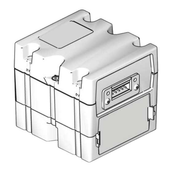
CGM with DeviceNet connector shown
3A1704H
EN
ti11985a
Advertisement
Table of Contents

Related Manuals for Graco 24J415


Summary of Contents for Graco 24J415
- Page 1 Installation Kit ™ For use with HFR systems to provide fieldbus communications abilities. For professional use only. Kit 24J415 Important Safety Instructions Read all warnings and instructions in your system manual. Save all instructions. ti11985a CGM with DeviceNet connector shown...
-
Page 2: Table Of Contents
406987 GCA CAN Cables, Reference Graco Standard Warranty ....26 Graco Information ......26... -
Page 3: Installation
Installation Installation 2. Install access cover (D). 3. Connect CAN cable from either CAN connection on the CGM to any CAN connection found on any other GCA device located on the machine. Attach the fer- rite suppressor to CGM end of the CAN cable. For additional extension cables, see GCA CAN Cables Reference manual. - Page 4 Installation 4. If used, connect the ethernet, DeviceNet, or PROFI- BUS cable to the CGM as applicable. Connect the other end of the cable to the FieldBus device. ti11985a . 3: Cable Connections 5. Connect cable (LC0032) to the MCM, port 2B, and a customer provided signal device.
-
Page 5: Setup
Setup Setup Gateway Screens PROFIBUS Fieldbus Screens These screens are shown only if you have a PROFIBUS Fieldbus Screens Page Fieldbus CGM installed. See Kits on page 2. PROFIBUS Screen 1 PROFINET This screen enables the user to set the device address, DeviceNet install date, location tag, function tag, and description. - Page 6 Setup PROFINET Fieldbus Screens These screens are shown only if you have a PROFINET Screen 3 Fieldbus CGM installed. See Kits on page 2. This screen displays the hardware revision, system serial number, and data map identification information. Screen 1 This screen enables the user to set the IP address, DHCP settings, subnet mask, gateway, and DNS infor- mation.
- Page 7 Setup EtherNet/IP Fieldbus Screens DeviceNet Fieldbus Screen These screens are shown only if you have a EtherNet/IP This screen is shown only if you have a DeviceNet Field- Fieldbus CGM installed. See Kits on page 2. bus CGM installed. See Kits on page 2. Screen 1 This screen enables the user to set the device address and baud rate, and to view the hardware revision, sys-...
-
Page 8: Maintenance
To install software upgrades: 1. Use correct software token stated in the table. See ti12334a1 ™ r_257396_3b9905_04b Graco Control Architecture Module Programming manual for instructions. NOTE: Upgrade all modules in the system to the software version on the token, even if you are replacing only one or two modules. -
Page 9: Available Internal Data
Available Internal Data Available Internal Data The following internal data with this system can be viewed and modified by your fieldbus master. NOTE: Refer to appropriate system manual for machine operation instructions. CGM Input from PLC CGM Output Units Byte Output Byte to PLC Input... - Page 10 Available Internal Data CGM Input from PLC CGM Output Units Byte Output Byte to PLC Input Descriptions 6 | Mix head Cleanout 0 = Open 0 = Clean Out Used for L-Head systems cleanout / (1 = Closed) Clean Out is open diagnostics only.
- Page 11 Available Internal Data CGM Input from PLC CGM Output Units Byte Output Byte to PLC Input Descriptions 14 | CGM Control 0 = ADM has 0 = CGM can Select via the PLC the control of the Enabled control of the only monitor system from either the CGM or the system...
- Page 12 Available Internal Data CGM Input from PLC CGM Output Units Byte Output Byte to PLC Input Descriptions Bit 1 = 1, Blue Bit 1 = 1, Blue Tank heat Tank heat ON enable Bit 2 = 1, Red Bit 2 = 1, Red Inline heat Inline heat ON enable...
- Page 13 Available Internal Data CGM Input from PLC CGM Output Units Byte Output Byte to PLC Input Descriptions Errors 9-12 The PLC ASCII 9-12 CGM ASCII Errors requiring acknowledgement Needing Output must value of the are presented on first in first out Acknowl- match the PLC error cur-...
- Page 14 Available Internal Data CGM Input from PLC CGM Output Units Byte Output Byte to PLC Input Descriptions Units and Units and Operating 13-14 Operating Info xx | Meaning Info Bit | Function 0-1 | Volume Units 0 0 | Gallons; Monitoring Only.
- Page 15 Available Internal Data CGM Input from PLC CGM Output Units Byte Output Byte to PLC Input Descriptions Ratio of Depending on system 23-24 Integer value Monitoring Only. The value from the the Blue / setup the units can be of the Blue / CGM is an integer and must be mul- Red mate- by weight or volume...
- Page 16 Available Internal Data CGM Input from PLC CGM Output Units Byte Output Byte to PLC Input Descriptions Red Hose Depending on system 53-54 Actual tem- Temp - setup the units can be perature Actual read in C or F Blue Tank Depending on system 55-56 Actual tem- Material -...
- Page 17 Available Internal Data CGM Input from PLC CGM Output Units Byte Output Byte to PLC Input Descriptions Tank Tank Level High = 3 Bits 3-0 = Red Monitoring Only. The values from Material Tank Level the CGM: Tank Level Mid = 2 Level Sta- Tank Level High = 3 tus Feed-...
- Page 18 Available Internal Data CGM Input from PLC CGM Output Units Byte Output Byte to PLC Input Descriptions Monitoring Only: Feedback Error types that need acknowledged will be indicated first. After all errors have been acknowledged then cur- rent error types will be indicated. Bits 3-0 = Bits 7-4 Status ADM Status...
- Page 19 Available Internal Data CGM Input from PLC CGM Output Units Byte Output Byte to PLC Input Descriptions Change Depending on system 13-16 Integer value of Changes current shot selected to a Dispense setup the units can be the requested new rate. The value outputted to the Flow Rate by weight, volume, rate in the dis-...
- Page 20 Available Internal Data CGM Input from PLC CGM Output Units Byte Output Byte to PLC Input Descriptions Change Depending on system 25-26 The tempera- The value outputted to the CGM Tempera- setup the units can be ture set points must be an integer and must be ture Con- read in C or F are limited by...
- Page 21 Available Internal Data Controlling Device ADM Screen Information when CGM Control is Started or ended CGM Control and Night Mode When the user or controlling device sets or clears the “CGM Control Enabled” bit, information provided on the When the controlling device sets the HFR into night ADM display may or may not be current.
- Page 22 Available Internal Data Timing Diagrams The following diagrams show the signal sequence of the CGM communication. Heart Beat Timing Diagram Heart Beat CGM Input CGM Output Bytes /Bit Bytes /Bit CGM HB - Normal PLC HB - Normal CGM HB - No HB PLC HB - Cycle Hi / Lo System Power Bit Diagram System Power Bit...
- Page 23 Available Internal Data System Startup and Dispensing Recirculation Diagram 3A1704H...
-
Page 24: Parts
Parts Parts Model 24J415 Ref Part Description 3† CGMxx0 MODULE, CGM 114984 SCREW, tapping, phillips pan head 16J526 TOKEN, map 12◆ 121000 CABLE, CAN, female / female 0.5 m 13◆ 121901 SUPPRESSOR, box snap, ferrite 16H821 TOKEN, GCA, upgrade, ADM32... - Page 25 Parts 3A1704H...
-
Page 26: Graco Standard Warranty
With the exception of any special, extended, or limited warranty published by Graco, Graco will, for a period of twelve months from the date of sale, repair or replace any part of the equipment determined by Graco to be defective.