Table of Contents
Advertisement
Instructions–Parts List
MODEL 482
Automatic Metering Valves
Used to provide precise dispense of medium– to high–viscosity sealants and
adhesives in a non–hazardous location.
3200 psi (22.0 MPa, 220 bar) Maximum Fluid Working Pressure
Part No. C02021, Series B
Model 482–B
7/8–18 uns externally threaded fluid inlet boss and 7/16–20 unf mounting hole
1/4 npt(f) material inlet, 1/8 npt(f) material outlet
Part No. C02022, Series C
Model 482–C
7/16–20 unf mounting hole
1/4 npt(f) material inlet, 1/8 npt(f) material outlet
Part No. C02025, Series B
Model 482–E
7/16–20 unf mounting hole
1/4 npt(f) material inlet, 1/4 npt(f) material outlet
Part No. C02078, Series B
Model 482–DA, with double acting air cylinder
7/16–20 unf mounting hole
1/4 npt(f) material inlet, 1/4 npt(f) material outlet
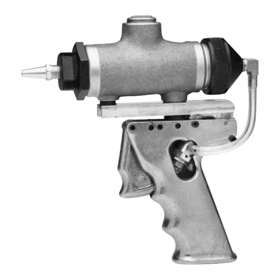
Part No. C02026
Model 482–HA; same as Part No. C02022, with trigger-actuated pistol grip handle
Part No. C02027
Model 482–MS, for moisture sensitive materials;
same as Part No. C02021, with seal fluid reservoir and plugged 7/16–20 mounting hole
Important Safety Instructions.
Read all warnings and instructions in this manual.
Save these instructions.
U.S. Patent Nos. 3,160,331 and 3,132,775
310543E
EN
Advertisement
Table of Contents


Need help?
Do you have a question about the 482 Series and is the answer not in the manual?
Questions and answers