Table of Contents
Advertisement
Quick Links
Instructions - Parts
2K Manual
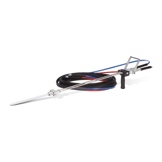
Dispense Valve
For use with two component proportioners to mix and dispense beads of non-abrasive
material. For professional use only.
Not approved for use in European explosive atmosphere locations.
Model 24R021
2000 psi (14 MPa, 137 bar) Maximum Fluid Working Pressure
Important Safety Instructions
Read all warnings and instructions in this manual
and the system manual. Save all instructions.
332198C
EN
ti20167a
Advertisement
Table of Contents

Related Manuals for Graco 24R021


Summary of Contents for Graco 24R021
- Page 1 For use with two component proportioners to mix and dispense beads of non-abrasive material. For professional use only. Not approved for use in European explosive atmosphere locations. Model 24R021 2000 psi (14 MPa, 137 bar) Maximum Fluid Working Pressure Important Safety Instructions Read all warnings and instructions in this manual and the system manual.
-
Page 2: Table Of Contents
Technical Data ......15 Graco Standard Warranty ....16 Related Manuals The following manuals are available at www.graco.com. -
Page 3: Warnings
Warnings Warnings The following warnings are for the setup, use, grounding, maintenance, and repair of this equipment. The exclama- tion point symbol alerts you to a general warning and the hazard symbols refer to procedure-specific risks. When these symbols appear in the body of this manual or on warning labels, refer back to these Warnings. Product-specific hazard symbols and warnings not covered in this section may appear throughout the body of this manual where applicable. - Page 4 Warnings WARNING EQUIPMENT MISUSE HAZARD Misuse can cause death or serious injury. • Do not operate the unit when fatigued or under the influence of drugs or alcohol. • Do not exceed the maximum working pressure or temperature rating of the lowest rated system component.
-
Page 5: Important Isocyanate (Iso) Information
Important Isocyanate (ISO) Information Important Isocyanate (ISO) Information Isocyanates (ISO) are catalysts used in two component materials. Isocyanate Conditions Moisture Sensitivity of Isocyanates Exposure to moisture (such as humidity) will cause ISO to partially cure; forming small, hard, abrasive crystals, Spraying or dispensing materials containing isocya- which become suspended in the fluid. -
Page 6: Changing Materials
Important Isocyanate (ISO) Information Changing Materials NOTICE Changing the material types used in your equipment requires special attention to avoid equipment damage and downtime. • When changing materials, flush the equipment multiple times to ensure it is thoroughly clean. • Always clean the fluid inlet strainers after flushing. -
Page 7: Installation
Installation Installation 3. Thread the handle (K) onto the manifold (L). 4. Connect the gun fluid supply hoses to the A (ISO) and B (RES) fluid inlets of gun. NOTE: Hoses are color coded: red for component A (ISO), blue for component B (RES). Red (ISO) usually is connected to the left side of the valve (as viewed from 1. -
Page 8: Operation
Operation Operation Prime 1. Use lever (H) to close the dispense valve inlet ball valves (J). NOTICE Always open and close lever (H) fully and quickly. Opening the valve partially or slowly will cause soft Perform this procedure whenever air is introduced into spots in the material and may shut down the propor- the material lines, such as after connecting the material tioner because of a pressure imbalance. -
Page 9: Ratio Checking
Operation Ratio Checking NOTE: Use the lowest proportioner pressure setting that produces the desired flow. NOTE: Use ratio check nozzle 255247 with retaining nut 512292. Purchase separately. NOTICE If the proportioner pressure setting is too high, any dif- The output mix ratio of your proportioner can be ferences in viscosity will cause a pressure differential checked by dispensing the two fluids separately out of that will result in improper mixing. -
Page 10: Pressure Relief Procedure
Operation Pressure Relief Procedure Daily Shutdown Follow the Pressure Relief Procedure whenever NOTE: For brief shutdowns, leave the cured mixer in you see this symbol. place until it is time to use a fresh mixer. This equipment stays pressurized until pressure is manually relieved. -
Page 11: Install Restrictors Or Plugs
Maintenance Install Restrictors or Plugs Sizing Restrictors If resin and hardener are at or near 1:1 ratio and viscos- ities are similar, add a few hundred psi pressure drop to each side to prevent check valve oscillation. Use the chart in F . -
Page 12: Troubleshooting
Troubleshooting Troubleshooting Problem Cause Solution Pressure is higher on one side Pump intake valve partially plugged. Clean pump intake valve. when setting pressure with function Air in hose. Fluid is compressible. Purge air from hose. knob. Unequal size hoses. Use matching hoses. Pressures are not balanced when Feathering the valve lever to When opening or closing the valve,... -
Page 13: Parts
Parts Parts 14 8 ti20581b NOTE: Apply thread sealant on all tapered thread fittings. Apply red thread locking liquid to the threads of the handle (2). When installing a new ball valve (8), remove the acorn nuts and handle from the ball valves (8). Keep the acorn nuts, discard the Make sure that #6 JIC adapter (13) is on the right and #5 JIC handle. -
Page 14: Accessories
Accessories Accessories Restrictors Gun Length Reduction To reduce the overall length of the gun from 47 in. 15E372 0.018 in. Orifice Restrictor (1194 mm) to 24 in. (610 mm), purchase two of each of 15E373 0.024 in. Orifice Restrictor the following fittings: 503279 and 151243. Use these fit- 15E374 0.032 in. -
Page 15: Typical Restrictor Pressure Drop
Technical Data Typical Restrictor Pressure Drop 2500 Key: (17.5, 175) 5000 cps, 1.0 gpm (3.8 lpm) 2000 (14.0, 140) 5000 cps, 0.25 gpm (0.95 lpm) 1000 cps, 0.25 gpm (0.95 lpm) 1500 (10.5, 105) 500 cps, 0.25 gpm (0.95 lpm) 200 cps, 0.25 gpm (0.95 lpm) 1000 (7.0, 70) -
Page 16: Graco Standard Warranty
With the exception of any special, extended, or limited warranty published by Graco, Graco will, for a period of twelve months from the date of sale, repair or replace any part of the equipment determined by Graco to be defective.
Need help?
Do you have a question about the 24R021 and is the answer not in the manual?
Questions and answers