
Related Manuals for Dyness VB4850


Summary of Contents for Dyness VB4850
- Page 1 VB4850 USER MANUAL Battery Module 48V/50Ah File version-20230724-V2-EN Information might be subject to change without notice during product improving.
-
Page 2: Table Of Contents
Equipment installation ..........................15 4 Use, maintenance and troubleshooting ................21 Instructions for use and operation of the battery system ............21 Alarm description and processing ....................22 Analysis and treatment of common faults ..................23 © Dyness reserves the copyright of this document. -
Page 3: Statement Of Law
Copyright of this document belongs to Dyness Digital Energy Technology Co., LTD.No part of this documentation maybe excerpted, reproduced, translated, annotated or duplicated in any form or by any means without the prior written permission of Dyness Digital Energy Technology Co., LTD.Infringement will be prosecuted. -
Page 4: Safety Precautions
Please charge the battery in 18 hours after it discharges fully and starts over-discharging protection. Formula of theoretical standby time: T=C/I (T is standby time, C is battery capacity, I is total current of all loads) © Dyness reserves the copyright of this document. -
Page 5: Preface
Preface Manual description The VB4850 lithium iron phosphate battery energy storage system can provide energy storage solutions for photovoltaic power generation users through parallel combination. During the day, the excess power of photovoltaic power generation can be stored in the battery. -
Page 6: Introduction
VB4850 lithium iron phosphate battery system is a standard battery system unit, customers can choose a certain number of VB4850 according to their needs, by connecting parallel to form a larger capacity battery pack, to meet the user's long-term power supply needs. -
Page 7: Nameplate Label
VB4850 Unit User Manual This battery product meets European directive requirements Dangerous goods warning label on the top of the battery module Nameplate Label Figure 1-1 Nameplate Label of VB4850 © Dyness reserves the copyright of this document. -
Page 8: Product Specification
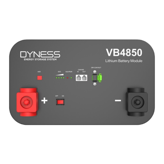
1.2KW Max Power 2.4KW Rated Charging Current Rated Discharging Current Interface Definition VB4850 product panel interface configuration and function. This section details the interface functions of the front panel of the device. © Dyness reserves the copyright of this document. - Page 9 VB4850 Unit User Manual 2 6 7 Figure 2-1 VB4850 The sketch of interface Item Definition Positive Terminal Battery output positive or parallel positive cable OFF/ON, Power Switch must be in the "ON" state when in use Negative Terminal Battery output negative or parallel negative cable DIP switch,definition in2.3.1...
- Page 10 CAN interface. The host summarizes the information of the entire battery system and communicates with the inverter through CAN or 485. If the master is the latest VB4850 battery with DIP switch: 1. The communication cable from the master CAN IN to the inverter comm port should be the correct one.
-
Page 11: Dry Contact Description Of Dry Contact Function
6. When you setup the master DIP as setting 1~4,all the slaves keep the DIP 0000,no need change. 7. If the energy storage system has only one VB4850, it is the master itself, and still follow the above steps. Note: For more information of matching inverter brands, please subject to the latest document <The list of compatibility between Dyness ESS and Inverters >... - Page 12 XGND PIN11 Green/White Reserve PIN12 Blue CANH PIN13 Blue/White CANL PIN14 Green Reserve PIN15 Brown/White XOUT PIN16 Brown Reserve Table 2-4 SOC/ALM/RUN Light instructions Battery LED1 LED2 LED3 LED4 State Shut down © Dyness reserves the copyright of this document.
-
Page 13: Battery Management System(Bms
When total voltage or any battery cell voltage reaches the protection value during charging, battery stops charging. When total voltage and all the cell voltage recover to rated return range, the protection is over. Current Protection Over Current Protection in Charging: © Dyness reserves the copyright of this document. - Page 14 The protection is over when it recovers to rated return range. Other Protection Short Circuit Protection: The battery does not allow external short circuit, which will damage the BMS. CAUTION Battery's maximum discharging current should be more than load's maximum working current. © Dyness reserves the copyright of this document.
-
Page 15: Installation And Configuration
15~30 Keep away from dust and messy zones. Tools and data Tools and meters that may be used are shown in Figure 3-2: © Dyness reserves the copyright of this document. - Page 16 In the process of unpacking, handle with care and protect the surface coating of the object; Open the package, the installation personnel should read the technical documents, verify the list, according to the configuration table and packing list, ensure objects are © Dyness reserves the copyright of this document.
-
Page 17: Equipment Installation
Equipment installation Table3-2 Installation steps Step1 Installation preparation 1. Confirm that the ON/OFF switch on the front panel of VB4850 unit is at the "OFF" state to ensure no live operation. Step2 Mechanical installation © Dyness reserves the copyright of this document. - Page 18 2.Connect the external CAN communication cable to the inverter. Installation preparation 1. Prepare equipment and tools for installation; 2. Check the VB4850 unit and confirm that the ON/OFF switch is at the "OFF" state to ensure no live operation. Mechanical installation Mechanical installation 1.
- Page 19 Schematic diagram of the wiring operation of the positive and negative terminals of the module 1. Unscrew the plastic nut on the plastic protective cover on the top of the terminal 2.Remove the plastic protective cover of the terminal. © Dyness reserves the copyright of this document.
- Page 20 The communication cable is plugged into the CAN IN interface on the panel (note that it is not CAN OUT) 2. From battery CAN IN to the inverter com port. © Dyness reserves the copyright of this document.
- Page 21 DIP mode according to the inverter model firstly,press the boat switch to ON.The battery panel LED will be on. Wiring diagram for parallel use of modules: Inverter Master Slave1 Slave2 Slave3 L1 Positive parallel power cable—between modules,L1=L2 © Dyness reserves the copyright of this document.
- Page 22 L2 Negative parallel power cable—between modules,L1=L2 L3 Total positive output power cable-to MCB L4 Total negative output power cable—to MCB L5 Communication cable between battery and inverter L6 Communication cable between modules © Dyness reserves the copyright of this document.
-
Page 23: Use, Maintenance And Troubleshooting
Table 4-1 Battery and inverter power matching table Off-grid Hybrid inverter VB4850 inverter EPS(backup ACoutput Min.parallel System energy(kWh) © Dyness reserves the copyright of this document. -
Page 24: Alarm Description And Processing
Alarm description and processing When the protection action or fault occurs in the system, the alarm signal will be given through the working status indicator on the front panel of the VB4850. You can query the specific alarm categories through battery monitor. -
Page 25: Analysis And Treatment Of Common Faults
Power connection check the cause of of power on, and the short-circuit the short circuit red light is on If you have any technical help or question, please contact the seller in time. © Dyness reserves the copyright of this document. - Page 26 Address: No. 511 Chenzhuang West Road, Sanshui Street, Jiangyan District, Taizhou City Email: service@dyness-tech.com Tel: +86 400 666 0655 Web: www.dyness.com Official Website Digital version access...
Need help?
Do you have a question about the VB4850 and is the answer not in the manual?
Questions and answers