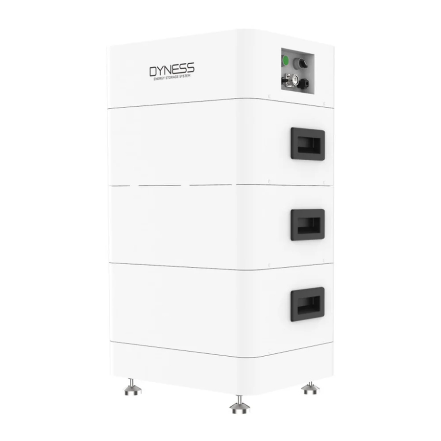
Dyness Tower Series, T7, T10, T14, T17, T21 Installation Guide
Also See for Tower Series:
- Quick installation manual (8 pages)
Advertisement
Table of Contents
Contents
Dyness Tower Series, T7, T10, T14, T17, T21 Installation Guide

Target Group

This manual and the tasks and procedures described herein are intended for use by skilled electricians only. A skilled electrician is defined as a trained and qualified electrician or installer who has all of the following skills and experience:
- Knowledge of the functional principles and operation of on-grid systems.
- Knowledge of the dangers and risks associated with installing and using electrical devices and acceptable mitigation methods.
- Knowledge of the installation of electrical devices.
- Knowledge of and adherence to this manual and all safety precautions and best practices.
- Please note that this is the quick reference guide only. It is a shortened assistance for the installation of the Battery HV and does not replace the original installation manual. The original installation manual must be read and understood completely before installation. Please download and view the installation manuals on this website:www.Dyness.com (Downloads).
- In order to ensure the normal operation of Tower, please be sure to update the firmware to the latest version and finish the configuration on the Tower webpage in accordance with this document.
- The system must be switched off before installation.
- Please make sure the system is switched off in case the system is not working. It should be repaired within one week, avoiding deep discharge and other problems happen.
- Please do not stack up batteries without protective package when storing or handling batteries, unless during installation.
Installation Environment

Tools

Packing list
| Item | Specification | Quantity | Figure |
| Communication Cable to Inverter | Standard, Black /L2000mm /RJ45 plug at both sides | 1 PCS |  |
| Communication Connector to BDU | RJ45 Waterproof connector | 1 PCS |  |
| M4 12pcs | M4*10 | 20PCS |  |
| M6 3 Sets of Combined Screws | M6*14 | 1 PCS |  |
| OT terminal for Ground | OT4-6 | 2 PCS |  |
| Power Cable Connector | To positive pole of battery | 1 PCS |  |
| Power Cable Connector | To negative pole of battery | 1PCS |  |
| Power Cable | Positive cable 6mm²,red, 2m | 1 PCS |  |
| Power Cable | Negative cable 6mm²,black, 2m | 1PCS |  |
Overall Design
- Limited to the voltage interval of the inverter, the number of HV9637 modules used by the Tower series is 2.
- Limited to the conversion conditions of the BDU internal DC, the maximum number of HV9637 modules in the Tower series of products is 6.
![Dyness - Tower Series - Overall Design Overall Design]()
- Unpacking
![]()
- Separate the BDU and Base
![]()
- Spacing
![]()
- Stacking and locking
Note: When assembling the BDU, ensure that the BDU circuit breaker is in "OFF" position.
![]()
- Connecting the cables
![]()
Note: We recommend that a circuit breaker is installed between the battery and the inverter to prevent the battery or the inverter being damaged when a short circuit occurs. - Earth connection
![]()
- Switching the battery system on
- First, set the BDU circuit breaker to "ON" position.
- Set the ON/OFF switch to "ON", press and hold the "WAKE" button for 10s. Release the button and the green light will stay on; the battery has been turned on successfully.
![Dyness - Tower Series - Switching the battery system on Switching the battery system on]()
- Parallel connection
![]()
Dyness supports a maximum of 4 clusters and a dedicated Combiner box (DCB-TW) must be configured.
Single cluster installation is the same as stand-alone. For others, please consult Dyness. - KOSTAL PLENTICORE PLUS
![Dyness - Tower Series - KOSTAL PLENTICORE PLUS - Communication cable connection KOSTAL PLENTICORE PLUS - Communication cable connection]()
10a Ingeteam (INGECON SUN STORAGE1 PLAY TL M)

10b Ingeteam (INGECON SUN STORAGE 100TL)

- Goodwe ET Inverter
Dyness has a standard communication network cable. It is recommended to use the GW configuration network cable and directly connect to the CAN port of the battery BDU.
Note: PV Master selects the TOWER PRO version, to ensure that the inverter is version 22 or later.
![Dyness - Tower Series - Goodwe ET Inverter connection Goodwe ET Inverter connection]()
- Solis RHI Series Hybrid Inverter
Use the configuration standard network cable.
![Dyness - Tower Series - Solis RHI Series Hybrid Inverter connection Solis RHI Series Hybrid Inverter connection]()
TOWER System Expansion
- Module expansion
It is necessary to ensure that the power of the added module is 100%, and the power of the expanded system is also 100%.
(The dealer is required to provide SOC100% module. If you operate by yourself, please follow the following steps.)
![Dyness - Tower Series - Module expansion - Step 1 Module expansion - Step 1]()
- Add the module to be charged between BDU and Base.
![Dyness - Tower Series - Module expansion - Step 2 Module expansion - Step 2]()
- Charge it with DC power supply until BDU is cut off, indicating that SOC is 100%.
![]()
- Add the module to be charged between BDU and Base.
Note: If you do not have the respective equipment, please ask the dealer to charge the module
Documents / Resources
References
Download manual
Here you can download full pdf version of manual, it may contain additional safety instructions, warranty information, FCC rules, etc.
Download Dyness Tower Series, T7, T10, T14, T17, T21 Installation Guide
Advertisement


Need help?
Do you have a question about the Tower Series and is the answer not in the manual?
Questions and answers