
Related Manuals for Xantrex Freedom X 1200


Summary of Contents for Xantrex Freedom X 1200
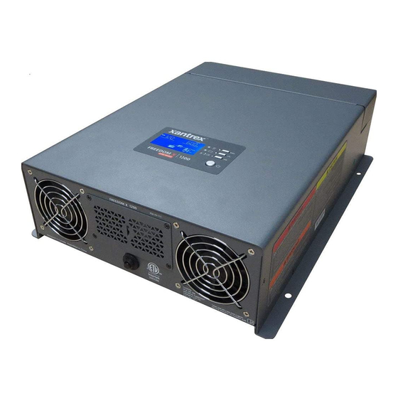
- Page 1 Unit with optional GFCI receptacle shown here. Owner’s Guide Freedom X 1200 Freedom X 1200 -120V Sine Wave 806-1212 Inverter...
- Page 3 ACCURACY OF THE TRANSLATION, THE ACCURACY CANNOT BE GUARANTEED. APPROVED CONTENT IS CONTAINED WITH THE ENGLISH LANGUAGE VERSION WHICH IS POSTED AT http://www.xantrex.com/. NOTE: Visit http://www.xantrex.com/ , click Products, select a Product category, select a Product, and search the Product Documents panel for a translation of the English guide, if available.
- Page 4 As soon as you open your product, record the following information and be sure to keep your proof of purchase. Serial Number ____________________________ Product Number ____________________________ Purchased From ____________________________ Purchase Date ____________________________ To view, download, or print the latest revision, visit the website shown under Contact Information. Freedom X 1200 Owner's Guide...
- Page 5 The purpose of this Owner’s Guide is to provide explanations and Amperes procedures for installing, operating, configuring, maintaining, and Amp-hours (a unit of battery capacity) troubleshooting a Freedom X 1200 -120V Sine Wave Inverter for Recreational, Commercial and Fleet Vehicle, or Marine Alternating Current [V] installations.
- Page 6 Degrees symbol commonly used for temperature °C Unit of degrees in Celsius scale °F Unit of degrees in Fahrenheit scale Percent, percentage Related Information You can find more information about Xantrex products and services at http://www.xantrex.com/. Freedom X 1200 Owner's Guide...
-
Page 7: Important Safety Instructions
IMPORTANT SAFETY INSTRUCTIONS ’ READ AND SAVE THIS WNER UIDE FOR FUTURE DANGER REFERENCE DANGER indicates a hazardous situation which, if not avoided, will result in This guide contains important safety instructions for the Freedom death or serious injury. X 1200 that must be followed during installation, operation, maintenance, and troubleshooting. -
Page 8: Product Safety Information
7. To reduce the risk of electrical shock, disconnect both AC and DC power to or from the inverter before attempting any maintenance or cleaning or working on any components connected to the inverter. Do not disconnect under load. Freedom X 1200 Owner's Guide... - Page 9 See NFPA 70E regulations. Instructions for installing the Freedom X 1200 -120V or CSA Z462. Sine Wave Inverter are provided here for use by qualified This equipment must only be installed and serviced by personnel only.
- Page 10 75°C. compartment. Failure to follow these instructions can result in injury or Failure to follow these instructions can result in death, serious equipment damage. injury, or equipment damage. Freedom X 1200 Owner's Guide...
- Page 11 PHYSICAL INJURY HAZARD Review cautionary markings on these products and on the This Freedom X 1200 -120V Sine Wave Inverter is not intended for engine. use by persons (including children) with reduced physical, sensory,...
-
Page 12: Precautions When Working With Batteries
Precautions When Working With Batteries Precautions When Working With NOTES: 1. Mount and place the Freedom X 1200 -120V Sine Wave Batteries Inverter unit away from batteries in a well ventilated compartment. IMPORTANT: Battery work and maintenance must be done by 2. -
Page 13: Precautions When Placing The Unit
Regulatory Failure to follow these instructions can result in death, serious injury, or equipment damage. The Freedom X 1200 inverter is certified to appropriate US and Canadian standards. For more information see Regulatory approvals on page 96. CAUTION The Freedom X 1200 inverter is intended to be used for recreational, commercial, or other mobile applications. -
Page 14: Fcc Information To The User
Many of the electrical components used in the Freedom X 1200 - to radio communications. 120V Sine Wave Inverter are made of recyclable material like However, there is no guarantee that interference will not occur in a particular installation. -
Page 15: Table Of Contents
Step 5: Connecting AC Output to an Existing AC Circuit Product Safety Information Step 6: Connecting the DC Cables Precautions When Working With Batteries Step 7: Connecting to Port(s) on the Freedom X 1200 Precautions When Placing the Unit Step 8: Testing Your Installation Regulatory... - Page 16 Transitioning from Battery Mode to Grid Mode Operating Limits Power Output Input Voltage Overload Conditions High Surge Loads Over-temperature Conditions Routine Maintenance Maintaining the Freedom X 1200 Unit Troubleshooting Pre-service Checklist Warning Messages Troubleshooting Reference Inverter Applications Freedom X 1200 Owner's Guide...
-
Page 17: Introduction
INTRODUCTION The Freedom X 1200 -120V Sine Wave Inverter is designed with integrated inverting functions and power management features suitable for marine, recreational, and commercial/fleet vehicle installations. Please read this section to familiarize yourself with the main performance and protection features of the Freedom X 1200. This... -
Page 18: Materials List
Figure 1 What’s In The Box Capability external events like brownouts, the Freedom NOTE: If any of the items are missing, contact Xantrex or any X 1200 automatically becomes an authorized Xantrex dealer for replacement. See Contact independent power source that supplies Information on page 1. - Page 19 The low battery shutdown for the inverter is power saving and the inverter can be manually selected by the Freedom X 1200 is inverting without a user from 10.5 to 12.1 VDC. load, it draws less than 0.6 amp of current from the battery (or battery Voltage Shutdown Delay Timer: bank).
- Page 20 The Freedom X 1200 AC Output The Freedom X 1200 is factory set to 60 Hz automatically shuts down when the limit is Frequency AC output frequency. It can be configured to exceeded.
-
Page 21: Features
FEATURES This section identifies the default settings and the hardware features of the Freedom X 1200 -120V Sine Wave Inverter. This section includes: AC/DC and GFCI Panel Display Panel Side Panel 975-0767-01-01... -
Page 22: Ac/Dc And Gfci Panel
Grounding lug provides a ground path for the Freedom X 1200 chassis to the DC system ground. See WARNING. Figure 2 AC/DC and GFCI Panel AC input terminal opening for routing AC input wiring. AC output terminal opening for routing AC output wiring. Freedom X 1200 Owner's Guide... - Page 23 AC/DC and GFCI Panel Item Description WARNING 15 A supplementary protector with reset button ELECTRICAL SHOCK HAZARD provides overload protection for the customer-supplied Use a torque screwdriver to tighten the bolt on the DC GFCI. Press to recover from an overload condition. In a ground lug to a torque of 23 in-lb (2.6 N-m) of force.
-
Page 24: Display Panel
Batt. MODE Three function buttons change status information displayed on the screen. Also, changes inverter settings. See Freedom X 1200 Display Panel on page 1 for detailed information on the panel’s buttons. Power [Standby] button is pressed for turning on the unit. The inverter turns on for the loads automatically. -
Page 25: Side Panel
Side Panel Side Panel Table 3 Side Panel Features Item Description Captive nut panel screw holds the wiring compartment cover in place. See WARNING above. Wiring compartment cover protects the wiring compartment from debris and keeps the cables secure. Using the captive nut panel screw, the cover can be opened and lifted out during wiring. - Page 26 This page is intentionally left blank. [2]...
-
Page 27: Installation
Step 4: Connecting the AC Input Wires Step 5: Connecting AC Output to an Existing AC Circuit Step 6: Connecting the DC Cables Step 7: Connecting to Port(s) on the Freedom X 1200 Step 8: Testing Your Installation Marine Installation... -
Page 28: Before You Begin The Installation
To prevent risk of fire, do not cover or obstruct ventilation openings. Do not mount in a zero-clearance compartment. Overheating may result. Failure to follow these instructions can result in death, serious injury, or equipment damage Freedom X 1200 Owner's Guide... -
Page 29: Installation Codes
Installation Codes Installation Codes Governing installation codes vary depending on the specific location and application of the installation. Some examples include the following: The U.S. National Electrical Code (NEC) The Canadian Electrical Code (CEC) The U.S. Code of Federal Regulations (CFRs) Canadian Standards Association/CSA Group (CSA) and the RV Industry Association (RVIA) standards and codes for installations in RVs... -
Page 30: Basic Installation Procedures
Basic Installation Procedures Basic Installation Procedures Installation Tools and Materials You will need the following to install the Freedom X 1200: This section provides sample installation information as a guide Wire stripper for your installation. For your convenience, the overall procedure... -
Page 31: Step 1: Designing The Installation
Figure 5 Typical Recreational Vehicle and Fleet Vehicle Step 1: Designing the Installation Installation Most Freedom X 1200 installations share common components, and some of these are briefly described in Step 1: Designing the Installation. Figure 5 shows some components and their relationship to each other in a typical recreational vehicle or fleet vehicle installation. - Page 32 Most safety requirements and electrical codes require the is usually the utility grid (power company) or an AC generator. An Freedom X 1200’s AC and DC inputs and outputs to be provided automatic or manual AC source selector switch can be used to...
- Page 33 AC output circuit breaker and breakers for individual load circuits. NOTICE RISK OF INVERTER DAMAGE Do not connect the Freedom X 1200 to a 120/240V, 3-pole, 4- wire circuit. Failure to follow these instructions can result in equipment damage.
- Page 34 AC Output Neutral Bonding Installation codes usually specify solid or stranded, overall size of The neutral conductor of the Freedom X 1200’s AC output circuit the conductors, and type and temperature rating of the insulation (that is, AC Output Neutral) is automatically connected to the around the wire.
- Page 35 Table 6 specifies the minimum recommended DC Freedom X 1200 in the inverter’s AC output distribution wiring cable size and maximum fuse size for the Freedom X 1200. The system. DC cables must be stranded, copper, and must be rated Table 5 GFCI...
- Page 36 400A. If the DC wiring is too small the voltage more which provides the DC current that the Freedom X 1200 drop from this surge will result in a voltage at the Freedom X 1200 converts to AC.
-
Page 37: Step 2: Choosing A Location For The Unit
Ventilated. Allow at least 5 inches of clearance at the fan Step 2: Choosing a Location for the end of the Freedom X 1200 for air flow, 1 inch on each side, Unit and 2 inches at the wiring access (AC and DC) end. The more clearance for ventilation around the unit, the better the performance. -
Page 38: Step 3: Mounting The Unit
4. Pilot-drill the mounting holes. 5. Fasten the Freedom X 1200 to the mounting surface. If you are mounting the unit on a wall or bulkhead, use #12 or #14 pan-head wood or sheet metal screws to secure it to the framing behind the wall or bulkhead. - Page 39 Failure to follow these instructions can result in death, serious injury, or equipment damage. Table 7 Equipment DC ground cable size The Freedom X 1200 has a ground lug on the side of the unit as Minimum equipment ground cable shown in Connecting the Equipment Ground. Follow the...
-
Page 40: Step 4: Connecting The Ac Input Wires
GFCI receptacle on the front General AC Wiring Considerations panel of the Freedom X 1200. If installed, you can also connect The AC input terminal is located inside the unit through the AC the inverter to an existing AC installation and then plug loads into panel’s ½"... - Page 41 Table 8 Required AC wire size vs. required breaker rating (connecting a line conductor to a neutral conductor, for example) Required Breaker Required Wire will cause the Freedom X 1200 to malfunction and may Size (A) Size (AWG) permanently damage the inverter. Damage caused by a reverse polarity connection is not covered by your warranty.
- Page 42 NOTE: AC Input hole - install a strain step 8c relief clamp (not shown) 7. Locate the Neutral, Ground and Line terminals on the AC input terminal labeled as N, G, and L respectively. Captive nut panel screw Freedom X 1200 Owner's Guide...
- Page 43 Basic Installation Procedures 8. Connect each AC wire into its corresponding terminal on the no-tool cage clamp terminal block. a. Lift the terminal lever (as shown in the previous figure). b. Insert the wire fully into the open slot. c. Lower the terminal lever to secure the wire in the slot. 9.
-
Page 44: Step 5: Connecting Ac Output To An Existing Ac Circuit
Freedom X 1200 AC output, and GFCI protection must be provided on every receptacle connected Do not connect the Freedom X 1200 to an AC branch circuit that to the AC hard wired installation. Other types may fail to has high-power consumption loads that exceed its output wattage operate properly when connected to the Freedom X 1200. - Page 45 Basic Installation Procedures There are three kinds of AC Output Connections. These are: AC Output Connections Connecting to an existing permanent AC output Figure 10 Routing and connecting the AC output wires circuit. Follow the instructions on AC Output Connections on page 43 and finish the installation there in that section.
- Page 46 9. Tighten the strain relief clamp to secure the wires. 10. Replace the wiring compartment cover (using a #2 Phillips torque screwdriver - see WARNING), if you are finished with connecting all the AC wires in the unit. Freedom X 1200 Owner's Guide...
- Page 47 Basic Installation Procedures GFCI Connections To install a GFCI on the unit: 1. Ensure AC and DC power sources are turned off, if not already done from AC Input Connections on page 40. NOTICE 2. Install the required circuit breaker in the inverter distribution panel receiving AC power from the inverter.
- Page 48 9. Replace the wiring compartment cover (using a #2 Phillips torque screwdriver - see WARNING), if you are finished with connecting all the AC wires in the unit. Freedom X 1200 Owner's Guide...
- Page 49 Basic Installation Procedures Figure 11 Parts inside the AC compartment Match the wire connectors to the corresponding terminals: 1. Connect each AC wire into its corresponding terminal on the 9 10 11 no-tool cage clamp terminal block by lifting the terminal lever, insert the ferrule fully into the open slot, and lowering the terminal lever to secure the wire in the slot.
- Page 50 4. Remove the knockout and install a ½" strain relief clamp. 5. Remove the GFCI cover plate by removing the two screws holding it in place. 6. Set the two screws aside. Freedom X 1200 Owner's Guide...
- Page 51 Basic Installation Procedures 7. Unpack the customer-supplied GFCI receptacle and lay out Figure 13 Parts inside the AC compartment the GFCI unit and the two mounting screws. See Ground Fault Circuit Interrupters (GFCIs) on page 33 for information on compatibility. 9 10 11 8.
- Page 52 AC wires in the unit. 6. Connect 4a to 7. 7. Attach and secure the GFCI receptacle to the panel inside the wiring compartment using the two mounting screws as shown in Figure 13 item 12. Freedom X 1200 Owner's Guide...
- Page 53 Basic Installation Procedures WARNING ELECTRICAL SHOCK HAZARD Use a torque screwdriver to tighten the captive nut panel screw to 5 in-lb (0.56 N-m) torque of force to ensure a proper ground connection and a required tool access to the wiring compartment. Failure to follow these instructions can result in death, serious injury, or equipment damage.
-
Page 54: Step 6: Connecting The Dc Cables
Figure 15 shows the DC end for your reference. Reversing the Reversing the positive and negative battery cables will connections may void the warranty. blow a fuse in the Freedom X 1200 and void your Figure 15 DC End warranty. - Page 55 Basic Installation Procedures 6. Strip ½" (13 mm) to ¾" (19 mm) of insulation from each To make the DC connections: cable end that will be connected to the inverter. The amount 1. Make sure the inverter is off and no AC or DC is connected stripped off will depend on the terminals chosen.
- Page 56 LED (see Step 6: Connecting the DC Cables) is not illuminated. Reversing the positive and negative battery cables will blow a fuse in the Freedom X 1200 and void your warranty. Failure to follow these instructions can result in equipment damage.
- Page 57 Basic Installation Procedures 15. Replace the wiring compartment cover by tightening the WARNING captive nut panel screw. See the following electrical shock hazard warning. FIRE HAZARD WARNING Do not complete the next step if flammable fumes are present. Explosion or fire may result if the disconnect/battery selector switch ELECTRICAL SHOCK HAZARD is not in the off position.
- Page 58 105 °C, and connect it between the Chassis Ground lug 1. The equipment grounding lug (DC ground lug) on the DC end of the Freedom X 1200 is used to connect the chassis of the and the boat’s DC grounding bus or engine negative bus. Use a Freedom X 1200 to your system’s DC negative connection...
-
Page 59: Step 7: Connecting To Port(S) On The Freedom X 1200
Figure 17 Ignition signal (ACC) input terminal Freedom X 1200 Connecting to ACC Signal The Freedom X 1200 can be wired to inhibit inverter operation in the absence of a vehicle’s (or vessel's) ignition control signal. This feature can avoid unnecessary battery drain that would otherwise occur if the inverter was operated without a charging source such as the vehicle alternator. - Page 60 Description of Ignition Control Features Connecting to the Remote Port For information about the features and instructions on changing The Freedom X 1200 can accommodate the Freedom X Remote the ignition control features, see Operation on page 63. Panel (sold separately; comes with 25ft-cable).
-
Page 61: Step 8: Testing Your Installation
Standby on the display panel does not disconnect DC or AC input hard wired to the Freedom X 1200. power to the Freedom X 1200. If shore power is present at AC input 4. Turn the lamp on to verify that it operates. - Page 62 AC MODE icon. If the test load operates, your installation is successful. NOTE: If the Power button on the Freedom X 1200 is turned ON, the Freedom X 1200 will automatically supply the appliances with inverter power if the shore power source fails or becomes disconnected.
-
Page 63: Marine Installation
Freedom X 1200 AC source panel that includes a max 30A (or a 15A if using a GFCI) circuit breaker that supplies the Freedom X 1200 Shore power – AC power supplied from a shore power connector Drip shield (see next page) -
Page 64: Drip Shield Installation
See Figure 19 . shields may not entirely protect you from this hazard. Do not Figure 20 Typical Drip Shield Placement on a Freedom X 1200 operate the unit when it is wet. Failure to follow these instructions can result in death, serious injury, or equipment damage. -
Page 65: Operation
OPERATION This section includes descriptions of the different modes and settings of the Freedom X 1200 -120V Sine Wave Inverter. This section includes: Freedom X 1200 Display Panel Status LED Indicators Function Buttons LCD Screen LCD Screen Icons 975-0767-01-01... -
Page 66: Freedom X 1200 Display Panel
Motor Loads on page 92. see "Function Buttons" on the facing page see "Function Buttons" on the facing page NOTE: Briefly pressing any function button activates backlight illumination. After 60 seconds of inactivity, backlight illumination turns off. Freedom X 1200 Owner's Guide... -
Page 67: Function Buttons
Freedom X 1200 Display Panel Function Buttons LCD Screen The LCD Screen changes depending on the operating mode of the Button Definition inverter. Figure 22 Parts of the LCD Screen Return to default screen or exit setting mode. Scroll to next screen or next selection. -
Page 68: Lcd Screen Icons
Batt. MODE loads from the battery. Appears in all modes. Indicates 0% battery capacity. Appears in AC mode only and sometimes in Fault mode. Indicates ~ 75–100% load capacity. Freedom X 1200 Owner's Guide... -
Page 69: Viewing Information During Battery Mode
Viewing Information During Battery Mode Viewing Information During Display Definition Battery Mode The display shows battery voltage at The LCD screen displays information related to battery mode 13.1 VDC and battery INPUT OUTPUT discharge current at operation. 0 ADC. Press the Scroll button to move from screen to screen. -
Page 70: Adjusting Settings In Configuration Mode
6. Repeat the previous steps to set other settings. 7. Press the button to exit the Configuration mode. AC MODE INPUT OUTPUT Batt. MODE setting number is displayed here setting value is displayed here Freedom X 1200 Owner's Guide... -
Page 71: Settings
Adjusting Settings in Configuration Mode Settings Setting Range of values Description Screen Screen (with default (Left (Right values) Side) Side) Exit Mode Power Save Timer 1 to 25 When the load is 50 watts or under, this value represents the number of hours inverter operation is going to continue before it is automatically turned off to preserve the battery. - Page 72 Latin American countries operating from 115 VAC/50 Hz. If the utility and inverter are set to 50 Hz, load appliances must also be rated to operate from 115 VAC/50 Hz power. Freedom X 1200 Owner's Guide...
- Page 73 Adjusting Settings in Configuration Mode Setting Range of values Description Screen Screen (with default (Left (Right values) Side) Side) Alarm Buzzer Audible Silent Reset to Factory Default Firmware version 975-0767-01-01...
-
Page 74: Operating In Battery Mode
AC output terminal of the unit. The battery power from the Freedom X 1200. You must disconnect from green status LED lights up to indicate the Freedom X 1200 is all power sources before working on any circuits connected to the using the battery to power the equipment and appliances. -
Page 75: Power Save Timer
When the inverter is in operation (in battery mode), you can check Power Save Mode how much power (displayed in kW) the Freedom X 1200 is By enabling the power save mode, also called load sensing, the supplying to the connected loads by observing the load capacity inverter can automatically go to power save mode by sending indicator on the LCD screen. -
Page 76: Operating Several Loads At Once
Turning the Audible Alarm ON or OFF The Freedom X 1200’s audible alarm can be muted. See Adjusting Feature Settings in Configuration Mode. Any warnings such as error or fault conditions or imminent shutdown are both displayed on the LCD screen and sounded on the alarm speakers. -
Page 77: Operating During Transition Between Grid Mode And Battery Mode
When the unit is operating in grid mode and shore power is lost, Mode the Freedom X 1200 has less than 20 milliseconds (default) to The Freedom X 1200’s advanced power management is capable switch to operating in battery mode (if the Power button is pressed of transitioning power from an AC source to DC source within a in the On position) and starts drawing power from the battery. -
Page 78: Operating Limits
Operating Limits Operating Limits Power Output The Freedom X 1200 can deliver up to 1200 W of continuous utility These are the operating limits of the Freedom X 1200: grade sine wave AC power. The wattage rating applies to resistive Power Output loads such as incandescent lights. -
Page 79: Input Voltage
Operating Limits Input Voltage Operating Battery Comment The allowable Freedom X 1200 input battery voltage ranges are Condition Voltage shown in the following table: The buzzer sounds a single 1 s Table 11 Input battery voltage range low battery alarm beep and the... -
Page 80: Overload Conditions
LCD screen turns on. shows a warning code E06. High Overload When the Freedom X 1200’s AC load increases to near Voltage 16.7 V Shutdown ~1300 W, the audible alarm beeps every five seconds Shutdown... -
Page 81: High Surge Loads
Some induction motors used in freezers, pumps, and other motor- operated equipment require high surge currents to start. The Freedom X 1200 may not be able to start some of these motors even though their rated steady state current draw is within the inverter’s limits. - Page 82 This page is intentionally left blank. [2]...
-
Page 83: Routine Maintenance
5 ROUTINE MAINTENANCE Regular maintenance is required to keep your Freedom X 1200 operating properly. This section includes: Maintaining the Freedom X 1200 Unit 975-0767-01-01... -
Page 84: Maintaining The Freedom X 1200 Unit
WARNING ELECTRICAL SHOCK HAZARD Turning the Power k button to Standby does not disconnect DC battery power from the Freedom X 1200. You must disconnect from all power sources before working on any circuits connected to the unit. Failure to follow these instructions can result in death, serious injury, or equipment damage. -
Page 85: Troubleshooting
TROUBLESHOOTING This section will help you narrow down the source of any problem you encounter. Before contacting customer service, please work through the steps listed in Pre-service Checklist on page 84. This section includes: Pre-service Checklist Warning Messages Troubleshooting Reference Inverter Applications Resistive Loads Motor Loads... -
Page 86: Pre-Service Checklist
Whether any extreme ambient conditions existed at Pre-service Checklist the time (temperature, vibrations, moisture, etc.) 3. If your Freedom X 1200 is not displaying an error code, check the following to make sure the present state of the WARNING installation allows proper operation:... -
Page 87: Warning Messages
Warning Messages Warning Messages Warning messages in the form of audible alarms and error codes that appear on the LCD screen to alert you to an impending system change. Warnings do not affect operation. With the exception of the error codes displayed on the screen, only the audible alarm can be turned ON or OFF. - Page 88 Check for proper DC cable sizing. see Maintaining the (inverting) Check for loose connections and tighten if necessary. Freedom X 1200 Unit on page 82. High battery voltage Battery mode Check for external charging sources, such as a PV charger and...
- Page 89 Warning Messages Error Code Condition Mode Action Check the fan for any obstruction and remove it. Large debris which may enter through the fan grille may impede Battery mode Fan lock alarm the fan blades from turning. When removing debris, do not (inverting) insert your fingers inside the grille.
-
Page 90: Troubleshooting Reference
Troubleshooting Reference WARNING ELECTRICAL SHOCK HAZARD Do not disassemble the Freedom X 1200. It does not contain any user-serviceable parts. Attempting to service the unit yourself could result in an electrical shock or burn. Failure to follow these instructions can result in death, serious injury, or equipment damage. - Page 91 Troubleshooting Reference Table 13 Troubleshooting reference Problem Possible Cause Solution Alarm does not sound when an error is Alarm is turned OFF. See Turning the Audible Alarm ON or OFF on page 74 encountered. and follow instructions to turn the alarm buzzer on again.
- Page 92 Battery voltage is too low Check DC connections and cable. (depending on setting, see Recharge battery. Maintaining the Freedom X 1200 Unit on page 82) to start inverting. LCD screen may show DC voltage as 000. No output voltage is shown in the LCD AC shore power is not available or Check AC shore power.
- Page 93 On and the ignition control switch on the front of the Freedom X 1200 unit is On (|). The fan turns on and off during AC The battery is discharged. Do not be alarmed, the unit is performing normally.
-
Page 94: Inverter Applications
Long Transfer Times accommodate the load, the size of battery bank required would be The Freedom X 1200 may take a long time (~ 0.1–0.2 s) to transfer impractical if the load is to be run for long periods. to Battery Mode when shore power is cut off while powering a motor load. -
Page 95: Specifications
SPECIFICATIONS This section summarizes the hardware and electrical specifications of the Freedom X 1200 -120V Sine Wave Inverter. Physical Specifications Environmental Specifications System Specifications Regulatory Approvals NOTE: Specifications are subject to change without prior notice. 975-0767-01-01... -
Page 96: Physical Specifications
5–95% RH, non-condensing Table 15 Product dimensions Operation may be limited based on the battery chemistry. For example, Lithium Iron Phosphate batteries have a limited charging temperature range. Follow specific battery manufacturer recommendations for the applicable chemistry. Freedom X 1200 Owner's Guide... -
Page 97: System Specifications
System Specifications System Specifications Table 18 DC input for inverting Freedom X 1200 Table 17 System specifications Operating voltage range LBCO voltage –16.5 VDC Freedom X 1200 Maximum non-operating voltage 0–24 VDC Transfer relay rating (A 30A surge (24A continuous) Nominal voltage 12.0 VDC... -
Page 98: Regulatory Approvals
Power derates to 85% when output voltage is set to 110/108 VAC. . To set the AC Frequency, see Adjusting Feature Settings in Configuration Mode on page 1. See Ground Fault Circuit Interrupters (GFCIs) on page 33 for approved device/s. Freedom X 1200 Owner's Guide... - Page 99 This page is intentionally left blank. [2]...
- Page 100 (Toll Free USA/Canada) +1 800 670 0707 (Outside USA/Canada) +1 408 987 6030 Printed in: 975-0767-01-01 Rev G...
Need help?
Do you have a question about the Freedom X 1200 and is the answer not in the manual?
Questions and answers
I’m sorry but I don’t understand what the manual for the panel means by ‘switch up’ and ‘down’. My switch goes in or out. Please advise as to how I can shut down the Xantrex whenever I am not using it to save vital battery capacity. Many thanks. Tom