
Related Manuals for Badger Meter Vortex RVL Series


Summary of Contents for Badger Meter Vortex RVL Series
- Page 1 Vortex Flow Meters Shedding Flow Meter RVL Series User Manual VRX-UM-00371-EN-04 (May 2022)
- Page 2 Vortex Flow Meters, Shedding Flow Meter Page ii VRX-UM-00371-EN-04 May 2022...
-
Page 3: Table Of Contents
User Manual CONTENTS Description Operating Principle Fluids General Installation Information Flow Rate and Range Requirements Piping Requirements Back Pressure Outputs K-Factors Electrical Installation Power Wiring Three-Pin Connection Option Mechanical Installation RVL Inline Installation RVL Wafer Installation RVL Tube Installation Maintenance Specifications RVL Inline RVL Wafer... - Page 4 Vortex Flow Meters, Shedding Flow Meter Page iv VRX-UM-00371-EN-04 May 2022...
-
Page 5: Description
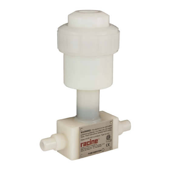
Description DESCRIPTION The RVL series meter uses vortex-shedding technology for repeatable flow measurement accurate to ±1 percent of full scale The meter has no moving parts, and any potential for fluid contamination is eliminated by the corrosion-resistant all plastic construction The meter includes a compact two-wire (4…20 mA) or three-wire (pulse) transmitter, contained within a conveniently replaceable plug-in electronics module All electronics are housed in a corrosion-resistant enclosure Unlike meters containing metal or moving parts, the RVL is perfect for aggressive or easily contaminated fluids Applications range from ultra-pure water to highly corrosive chemicals and slurries Units can be recalibrated and the meter output span... -
Page 6: General Installation Information
General Installation Information GENERAL INSTALLATION INFORMATION Before installing the meter: • Find an area for installation away from large electrical motors, transformers or other devices that can produce high electromagnetic or electrostatic fields The vortex transmitter contains electric circuitry that can be affected by these interferences •... - Page 7 General Installation Information Piping Requirements Accuracy Repeatability (pipe diameters) Configuration (full scale) (of point) Inlet Outlet 1 plane change 1 plane change w/outlet valve ±1 00% 0 25% 2 plane changes 2 plane changes w/outlet valve 20 Dia 5 Dia Minimum Minimum Flow...
- Page 8 General Installation Information Piping Requirements Accuracy Repeatability Configuration (full scale) (of point) Inlet Outlet 1 plane change 5 PD 20 PD 1 plane change w/outlet valve 10 PD ±1 50% 0 25% 2 plane changes 5 PD 27 PD 2 plane changes w/outlet valve 10 PD 20 Dia 5 Dia...
- Page 9 General Installation Information Piping Requirements Accuracy Repeatability Configuration (full scale) (of point) Inlet Outlet 1 plane change 5 PD 20 PD 1 plane change w/outlet valve 10 PD ±1 00% 0 25% 2 plane changes 5 PD 27 PD 2 plane changes w/outlet valve 10 PD Two Plane Two Plane...
-
Page 10: Back Pressure
General Installation Information Back Pressure Back pressure, the pressure immediately downstream of the meter, must be maintained above a minimum level to avoid cavitation For most applications this may be ignored if the flow rate is less than 75% of maximum For other applications, use the following formula to calculate the minimum back pressure ∆... -
Page 11: Electrical Installation
Electrical Installation ELECTRICAL INSTALLATION Power Use the following guidelines when selecting a power source: • Use an 8…28V DC power supply The specific connection depends on which output is option is used • Use clean electrical line power • Do not operate this unit on circuits with noisy components such as fluorescent lights, relays, compressors or variable frequency drives •... - Page 12 Electrical Installation The voltage provided by the receiver must be within the limits shown in Figure 8 1100 1000 Supply Voltage – 8V DC = Maximum Loop Resistance 0.02 Operate in the Shaded Region Supply Voltage (V DC) Figure 8: Supply voltage chart To use this figure: 1 Add the resistance of all the receivers, indicators and the wire in the loop If the wire resistance is unknown, use a value of 50 ohm for a twisted wire of 1000 feet or less with a gauge of #22 awg or heavier...
-
Page 13: Three-Pin Connection Option
Electrical Installation Three-Pin Connection Option An optional three-pin connection is available for when the transmitter/meter combination is mounted remotely from the power source/receiver The mating connector is PN RF8687000 White 4…20 mA Input 8…28V DC +8-28 VDC Output Output Black Meter –... -
Page 14: Mechanical Installation
Mechanical Installation MECHANICAL INSTALLATION RVL Inline Installation For proper installation, follow these guidelines: • Install the meter where pipe vibration is minimal • Use the upstream and downstream piping requirements shown in “Piping Requirements” on page 6 • Do not use upstream valves to control flow rate Always keep upstream valves fully open •... -
Page 15: Rvl Wafer Installation
Mechanical Installation RVL Wafer Installation The RVL Wafer series transmitters are designed with wafer style flow bodies, that mount easily between standard ANSI style pipe flanges For proper installation, follow these guidelines: • Install the meter where pipe vibration is minimal •... -
Page 16: Rvl Tube Installation
Maintenance RVL Tube Installation For proper installation, follow these guidelines: • Install the meter where pipe vibration is minimal • Use the upstream and downstream piping requirements shown in “Piping Requirements” on page 6 • Do not use upstream valves to control flow rate Always keep upstream valves fully open •... -
Page 17: Specifications
Specifications SPECIFICATIONS RVL Inline Fluid Liquids Connection NPT Female or Butt (PVDF only) 12:1 for 1/2…2 in (12 7…50 8 mm) meters Turndown Ratio 8:1 for 1/4 in (6 35 mm) meter ±1% of full scale (4…20 mA) Accuracy ±2% of full scale, frequency pulse Repeatability ±0 25% of actual flow PVC standard... -
Page 18: Rvl Wafer
Specifications RVL Wafer Fluid Liquids Connection Wafer Turndown Ratio 12:1 ±1% of full scale (4…20 mA) Accuracy ±2% of full scale, frequency pulse Repeatability ±0 25% of actual flow PVC standard Materials CPVC, Polypropylene, PVDF optional 4…20 mA standard Output Signals Frequency pulse optional push-pull driver 150 mA sink or source Power Supply 8…28V DC... -
Page 19: Rvl Tube
Specifications RVL Tube Fluid Liquids Connection Tube (Flare end) 12:1 for 3/4 in (19 05 mm) and 1 in (25 4 mm) meters Turndown Ratio 8:1 for 1/2 in (12 7 mm) meter ±1% of full scale (4…20 mA) Accuracy ±2% of full scale, frequency pulse Repeatability ±0 25% of actual flow... -
Page 20: Dimensions
Dimensions DIMENSIONS RVL Inline Cord Grip Cord Grip Cover Conduit Adapter Terminal Strip Electronics Module Three-Pin Connector NPT/BUTT Flow Sensor Body Figure 17: RVL inline dimensions PVC/CPVC Size in. (mm) in. (mm) in. (mm) in. (mm) in. (mm) in. (mm) in. -
Page 21: Rvl Wafer
Dimensions RVL Wafer Cord Grip Cord Grip Cover Conduit Adapter Terminal Strip Electronics Module Three-Pin Connector Flow Sensor Body Figure 18: RVL wafer dimensions RVL (Wafer) Dimensions PP/PVC/CPVC/PVDF Size in. (mm) in. (mm) in. (mm) in. (mm) in. (mm) 1/2 in (12 7 mm) 5 85 (149) 0 78 (20) 2 03 (52) -
Page 22: Troubleshooting
Troubleshooting TROUBLESHOOTING If difficulty is encountered, locate the symptom most likely present and follow the appropriate instructions Current Loop No Current Output • Place a DC voltmeter across the two terminal block screws With the electronics module powered there must be at least 8V DC present If there is less than 8V DC, but more than 0V DC, check the power source for sufficient voltage to drive the loop, as shown in Figure 8 on page 12... -
Page 23: Calibration Certificate Sample
Calibration Certificate Sample CALIBRATION CERTIFICATE SAMPLE Calibration Report Unit Under Test (UUT) Information: Master Meter: Description: 3/4 in In-Line NPT End Flow Meter Std uncertainty: ±0 25% Model Number: RVL075-N 1 VNN Traceability No: 30400/31801 Serial Number: 99999 Model No: FT8-8N EXW-LEG-5/FT-16 NEXW-LEG-1 Sensor Type: Vortex Shedding... - Page 24 Trademarks appearing in this document are the property of their respective entities Due to continuous research, product improvements and enhancements, Badger Meter reserves the right to change product or system specifications without notice, except to the extent an outstanding contractual obligation exists © 2022 Badger Meter, Inc All rights reserved www.badgermeter.com...
Need help?
Do you have a question about the Vortex RVL Series and is the answer not in the manual?
Questions and answers