Table of Contents
Advertisement
Quick Links
Advertisement
Chapters
Table of Contents

Related Manuals for IEI Technology AFL3-W15C-ADLP


Summary of Contents for IEI Technology AFL3-W15C-ADLP
- Page 1 AFL3-W15C/W19C/W22C-ADLP MODEL: AFL3-W15C/W19C/W22C-ADLP Flat Bezel Panel PC with Intel® Alder Lake-P Processor, PCAP Touchscreen, Four USB 3.2 Gen 1, Dual 2.5GbE LAN, RS- 232/422/485, Wi-Fi 802.11a/b/g/n/ac/ax and RoHS User Manual User Manual Page I Rev. 1.00 - September 5, 2023 [MODEL NAME]...
- Page 2 AFL3-W15C/W19C/W22C-ADLP Revision Date Version Changes September 5, 2023 1.00 Initial release Page II [MODEL NAME]...
- Page 3 AFL3-W15C/W19C/W22C-ADLP Safety Instructions Warning! Read the user manual before connecting the system to the power source. Vorsicht! Bitte lesen Sie die Bedienungsanleitung, bevor Sie das System an eine Stromquelle anschließen. Attention! Avant de brancher le système à la source d'alimentation, consultez le mode d'emploi.
- Page 4 AFL3-W15C/W19C/W22C-ADLP Warning! Use only the adapter and power cord approved for this system. Use of another type of adapter may risk fire or explosion. Please refer to the user manual for the power adapter specifications. Vorsicht! Nur zugelassene Netzteile und Netzkabel dürfen verwendet werden. Die Benutzung von anderen Netzteilen kann einen Brand oder eine Explosion zur Folge haben.
- Page 5 AFL3-W15C/W19C/W22C-ADLP Warning! Operation of this equipment in a residential environment could cause radio interference. Vorsicht! Der Betrieb dieses Geräts in einer Wohnumgebung kann zu Funkstörungen führen. Warning! L'utilisation de cet équipement dans un environnement résidentiel peut provoquer des interférences radio. Avvertenza! Il funzionamento di questa apparecchiatura in un ambiente residenziale potrebbe causare interferenze radio.
- Page 6 AFL3-W15C/W19C/W22C-ADLP Copyright COPYRIGHT NOTICE The information in this document is subject to change without prior notice in order to improve reliability, design and function and does not represent a commitment on the part of the manufacturer. In no event will the manufacturer be liable for direct, indirect, special, incidental, or consequential damages arising out of the use or inability to use the product or documentation, even if advised of the possibility of such damages.
- Page 7 AFL3-W15C/W19C/W22C-ADLP Manual Conventions WARNING Warnings appear where overlooked details may cause damage to the equipment or result in personal injury. Warnings should be taken seriously. CAUTION Cautionary messages should be heeded to help reduce the chance of losing data or damaging the product. NOTE These messages inform the reader of essential but non-critical information.
-
Page 8: Table Of Contents
.................... 8 YSTEM PECIFICATIONS 1.8.1 WLAN/Bluetooth Frequency Range and Power ..........11 1.9 D ......................12 IMENSIONS 1.9.1 AFL3-W15C-ADLP Dimensions ..............12 1.9.2 AFL3-W19C-ADLP Dimensions ..............13 1.9.3 AFL3-W22C-ADLP Dimensions ..............14 2 UNPACKING ....................... 15 2.1 U ......................16 NPACKING 2.2 P... - Page 9 AFL3-W15C/W19C/W22C-ADLP 3.9 M ..................32 OUNTING THE YSTEM 3.9.1 Wall Mounting ....................32 3.9.2 Panel Mounting ....................35 3.9.3 Cabinet and Rack Installation ................. 39 3.9.4 Arm Mounting ....................41 3.9.5 Stand Mounting ....................44 3.10 P ................... 45 OWERING N THE YSTEM 3.11 R...
- Page 10 AFL3-W15C/W19C/W22C-ADLP 5 SYSTEM MAINTENANCE ..................94 5.1 S ..............95 YSTEM AINTENANCE NTRODUCTION 5.2 A ..................95 STATIC RECAUTIONS 5.3 T ....................96 URN OFF THE OWER 5.4 SO-DIMM M ................ 96 ODULE EPLACEMENT 6 INTERFACE CONNECTORS ................... 99 6.1 P ..............
- Page 11 AFL3-W15C/W19C/W22C-ADLP 6.3.4 USB 3.2 Gen 1 Connectors (USB3_CON2) ............ 112 6.3.5 RS-232 RJ-45 Serial Port (COM2) ..............113 6.3.6 RS-232/422/485 DB-9 Serial Port (COM1) ............ 113 6.3.7 RJ45 LAN Connector ( LAN 2 ) ..............114 6.3.8 RJ45 LAN Connector ( LAN 1) ............... 114 6.3.9 RJ45 LAN Connector(RJ-IPMI1) ..............
- Page 12 Figure 1-7: AFL3-W19C-ADLP Dimensions (mm) ..............13 Figure 1-8: AFL3-W22C-ADLP Dimensions (mm) ..............14 Figure 3-1: AFL3-W15C/W19C/W22C-ADLP Back Cover Retention Screws ......23 Figure 3-2: AFL3-W15C-ADLP Aluminum Cover Retention Screws ........24 Figure 3-3: AFL3-W19C-ADLP Aluminum Cover Retention Screws ........24 Figure 3-4: AFL3-W22C-ADLP Aluminum Cover Retention Screws ........25 Figure 3-5: Lift the Aluminum Cover ..................26...
- Page 13 AFL3-W15C/W19C/W22C-ADLP Figure 3-24: Install into a Rack/Cabinet ..................41 Figure 3-25: Arm Mounting Retention Screw Holes ..............43 Figure 3-26: Arm Mounting ......................44 Figure 3-27: Stand Mounting (Stand-A/Bxx) ................45 Figure 3-28: Powering On the System ..................46 Figure 3-29: Reset Button Location ....................47 Figure 4-1:BIOS Starting Menu ....................50 Figure 5-1: SO-DIMM module Location ..................97 Figure 5-2: SO-DIMM Installation ....................98...
- Page 14 AFL3-W15C/W19C/W22C-ADLP List of Tables Table 1-1:Model Variations ......................3 Table 1-2: Supported E-Window Modules ..................7 Table 1-3: System Specifications ....................10 Table 1-2: WLAN/Bluetooth Frequency Range and Power............11 Table 4-1:BIOS Navigation Keys ....................51 Table 4-2:BIOS ON-screen Keys ....................52 Table 6-1:Peripheral Interface Connectors ................101 Table 6-2:M.2 M-key Slot (M2_M_KEY) Pinouts ...............103 Table 6-3:Set Voltage Connector(INV1) Pinouts ..............103 Table 6-4:LVDS VDD Power Selection (J_PANEL1, J_PW1) Pinouts ........103...
- Page 15 AFL3-W15C/W19C/W22C-ADLP Table 6-26: USB 3.2 Gen 1 Connectors (USB3_CON2) Pinouts ..........113 Table 6-27: RS-232 RJ-45 Serial Port (COM2) Pinouts ............113 Table 6-28: RS-232/422/485 DB-9 Serial Port (COM1) Pinouts ..........113 Table 6-29:RJ45 LAN Connector ( LAN 2 ) ................114 Table 6-30:RJ45 LAN Connector ( LAN 1) ................114 Table 6-31:RJ45 LAN Connector(RJ-IPMI1) ................115 Table 6-32: Preconfigured Jumpers ..................116 Table 6-33: LVDS Voltage Selection Jumper (J_VLVDS1) Settings ........116...
- Page 16 AFL3-W15C/W19C/W22C-ADLP List of BIOS Menus BIOS Menu 1:Main (1/2) ........................54 BIOS Menu 2: Main(2/2) ........................55 BIOS Menu 3:Advanced .......................57 BIOS Menu 4:CPU Configuration(1/3)..................58 BIOS Menu 5::CPU Configuration(2/3) ..................59 BIOS Menu 6::CPU Configuration(3/3) ..................59 BIOS Menu 7:PCH-FW Configuration ..................63 BIOS Menu 8: Trusted Computing ....................64 BIOS Menu 9: IT5571 IO Configuration..................65 BIOS Menu 10: Serial Port 1 Configuration ................66 BIOS Menu 11: Serial Port 2 Configuration ................67...
-
Page 17: Introduction
AFL3-W15C/W19C/W22C-ADLP Chapter Introduction Page 1... -
Page 18: Overview
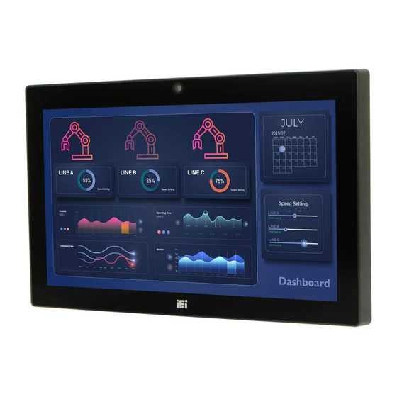
AFL3-W15C/W19C/W22C-ADLP 1.1 Overview Figure 1-1: AFL3-W15C/W19C/W22C-ADLP Flat Bezel Panel PC The AFL3-W15C/W19C/W22C-ADLP series is a Intel® Alder Lake P Core™ powered flat bezel touchscreen panel PC with a rich variety of functions and peripherals. The flat-bezel design is ideal for easy and simplified integration into various applications. The Intel®... -
Page 19: Model Variations
AFL3-W15C/W19C/W22C-ADLP 1.2 Model Variations There are several models in the AFL3-W15C/W19C/W22C-ADLP series. The model numbers and model variations are listed below. Model Size Processor AFL3-W15C-ADLP-i3/8G-R10 Intel® Core™ i3-1220P 15.6" AFL3-W15C-ADLP-i5/8G-R10 Intel® Core™ i5-1240P AFL3-W15C-ADLP-i7/8G-R10 Intel® Core™ i7-1260P AFL3-W19C-ADLP-i3/8G-R10 Intel® Core™ i3-1220P 18.5"... -
Page 20: Front Panel
AFL3-W15C/W19C/W22C-ADLP 1.4 Front Panel The front side of the AFL3-W15C/W19C/W22C-ADLP is a flat-bezel panel with a TFT LCD screen surrounded by a PC/ABS plastic frame (Figure 1-2). Figure 1-2: Front View There is a power LED indicator located on the front panel. The status descriptions of the power LED indicator are listed below. -
Page 21: Bottom Panel
AFL3-W15C/W19C/W22C-ADLP 1.5 Bottom Panel The bottom panel of the AFL3-W15C/W19C/W22C-ADLP has the following connectors and switches . Figure 1-3: AFL3-W15C/W19C/W22C-ADLP Bottom Panel Page 5... -
Page 22: Rear Panel
AFL3-W15C/W19C/W22C-ADLP 1.6 Rear Panel The rear panel has two speakers and retention screw holes that support VESA mounting. The rear panel also has several retention screw holes for installing the optional barcode scanner and magnetic stripe card reader. Figure 1-4: AFL3-W15C/W19C/W22C-ADLP Rear View Page 6... -
Page 23: Side Panel
All listed E-Window modules are for ATO (assembly-to-order) only. Part No. Description Supported Model iM2-LVDS01-R10 M.2 to Single/Dual Channel LVDS Module AFL3-W15C-ADLP AFL3-W19C-ADLP AFL3-W22C-ADLP iM2-CAN-2P-R10 M.2 B Key + M Key card supports 2-Port CAN B AFL3-W15C-ADLP us with Isolation Protection, RoHs... -
Page 24: System Specifications
AFL3-W15C/W19C/W22C-ADLP 1.8 System Specifications The technical specifications for the AFL3-W15C/W19C/W22C-ADLP systems are listed in Table 1-3. Specification AFL3-W15C-ADLP AFL3-W19C-ADLP AFL3-W22C-ADLP LCD Size 15.6" (16:10) 18.5" (16:10) 21.5" (16:10) Max. Resolution 1920 (W) x 1080 (H) 1920 (W) x 1080 (H) - Page 25 AFL3-W15C/W19C/W22C-ADLP Camera 2-megapixel with low light function and digital microphone Wireless & Bluetooth IEEE 802.11ax 2T2R module (Wi-Fi 6E) with BT v5.2 (M.2 2230 E-key) RFID Reader Mifare 13.56 MHz card reader (optional) Card Reader Magnetic stripe card reader (optional) Construction Material PC+ABS plastic Thermal Design...
-
Page 26: Table 1-3: System Specifications
AFL3-W15C/W19C/W22C-ADLP 1 x Power switch 1 x AT/ATX switch 1 x ClearCMOS Button 1 x Reset button 1 x 12V DC Jack Table 1-3: System Specifications Page 10... -
Page 27: Wlan/Bluetooth Frequency Range And Power
AFL3-W15C/W19C/W22C-ADLP 1.8.1 WLAN/Bluetooth Frequency Range and Power Technology Frequency range/MHz Max.E.I.R.P/dBm WLAN 2.4GHz 2400-2483.5 WLAN 5GHz 5150-5250 WLAN 5GHz 5250-5350 WLAN 5GHz 5470-5725 WLAN 5GHz 5725-5850 13.98 WLAN 6GHz 5945-6425 Bluetooth BR/EDR 2402-2480 Bluetooth LE 2402-2480 Table 1-4: WLAN/Bluetooth Frequency Range and Power WARNING! This equipment complies with CE radiation exposure limits set forth for an uncontrolled environment. -
Page 28: Dimensions
AFL3-W15C/W19C/W22C-ADLP 1.9 Dimensions The following sections list the dimensions of each model. 1.9.1 AFL3-W15C-ADLP Dimensions The AFL3-W15C-ADLP dimensions are shown below. Figure 1-6: AFL3-W15C-ADLP Dimensions (mm) Page 12... -
Page 29: Afl3-W19C-Adlp Dimensions
AFL3-W15C/W19C/W22C-ADLP 1.9.2 AFL3-W19C-ADLP Dimensions The AFL3-W19C-ADLP dimensions are shown below. Figure 1-7: AFL3-W19C-ADLP Dimensions (mm) Page 13... -
Page 30: Afl3-W22C-Adlp Dimensions
AFL3-W15C/W19C/W22C-ADLP 1.9.3 AFL3-W22C-ADLP Dimensions The AFL3-W22C-ADLP dimensions are shown below. Figure 1-8: AFL3-W22C-ADLP Dimensions (mm) Page 14... -
Page 31: Unpacking
AFL3-W15C/W19C/W22C-ADLP Chapter Unpacking Page 15... -
Page 32: Unpacking
AFL3-W15C/W19C/W22C-ADLP 2.1 Unpacking To unpack the flat bezel panel PC, follow the steps below: WARNING! The front side LCD screen has a protective plastic cover stuck to the screen. Only remove the plastic cover after the flat bezel panel PC has been properly installed. -
Page 33: Optional Items
AFL3-W15C/W19C/W22C-ADLP The AFL3-W15C/W19C/W22C-ADLP flat bezel panel PC is shipped with the following components: Quantity Item Image AFL3-W15C/W19C/W22C-ADLP panel PC 96 W power adapter (P/N: 63040-010096-100-RS) Power cord Screws (M4*6) for VESA mounting Screws (M3*4) for HDD installation 2.3 Optional Items The following are optional components which may be separately purchased: Item and Part Number Image... - Page 34 AFL3-W15C/W19C/W22C-ADLP Item and Part Number Image Panel mounting kit (P/N: AFL3PK-W15A-R10 for W15C) (P/N: AFL3PK-W19C-R10 for W19C & W22C) Rack mounting kit (P/N: AFL3RK-W15B-R10 for W15C) (P/N: ARM-11-RS) (P/N: ARM-31-RS) Stand for VESA 100 (P/N: STAND-A19-RS) Page 18...
- Page 35 AFL3-W15C/W19C/W22C-ADLP Item and Part Number Image Stand for VESA 75/VESA 100 (P/N: STAND-C19-R10) Magnetic card reader (P/N: AFL3P-W10MSR-U-R10) Barcode scanner (P/N: AFL3-2D-R10) If any of these items are missing or damaged, contact the distributor or sales representative immediately. Page 19...
-
Page 36: Installation
AFL3-W15C/W19C/W22C-ADLP Chapter Installation Page 20... -
Page 37: Anti-Static Precautions
AFL3-W15C/W19C/W22C-ADLP 3.1 Anti-static Precautions WARNING: Failure to take ESD precautions during the maintenance of the AFL3- W15C/W19C/W22C-ADLP may result in permanent damage to the AFL3-W15C/W19C/W22C-ADLP and severe injury to the user. Electrostatic discharge (ESD) can cause serious damage to electronic components, including the AFL3-W15C/W19C/W22C-ADLP. -
Page 38: Installation And Configuration Steps
Step 1: Remove the retention screws from the back cover. Two types of screw are used for securing the plastic cover of the AFL3-W15C-ADLP. See Figure 3-1 for detail. Be aware of this for reinstalling the plastic cover. Page 22... -
Page 39: Figure 3-1: Afl3-W15C/W19C/W22C-Adlp Back Cover Retention Screws
AFL3-W15C/W19C/W22C-ADLP Figure 3-1: AFL3-W15C/W19C/W22C-ADLP Back Cover Retention Screws Step 2: Lift the plastic back cover off the AFL3-W15C/W19C/W22C-ADLP. Step 3: Remove the retention screws from the internal aluminum cover. Two types of screw are used for securing the aluminum cover. See the following diagrams for detail. -
Page 40: Figure 3-2: Afl3-W15C-Adlp Aluminum Cover Retention Screws
AFL3-W15C/W19C/W22C-ADLP Figure 3-2: AFL3-W15C-ADLP Aluminum Cover Retention Screws Figure 3-3: AFL3-W19C-ADLP Aluminum Cover Retention Screws Page 24... -
Page 41: Figure 3-4: Afl3-W22C-Adlp Aluminum Cover Retention Screws
AFL3-W15C/W19C/W22C-ADLP Figure 3-4: AFL3-W22C-ADLP Aluminum Cover Retention Screws Step 4: Lift the aluminum cover off the AFL3-W15C/W19C/W22C-ADLP. A thermal pad is attached under the center of the aluminum cover. To easily remove the cover, turn the cover in a clockwise direction first to detach the thermal pad before lifting the cover (Figure 3-5). -
Page 42: Module Installation
AFL3-W15C/W19C/W22C-ADLP Figure 3-5: Lift the Aluminum Cover 3.5 M.2 Module Installation The AFL3-W15C/W19C/W22C-ADLP has an M.2 2280 M-key slot (PCIe signal). To install an M.2 module into the AFL3-W15C/W19C/W22C-ADLP, please follow the steps below: Step 1: Remove the plastic back cover and the internal aluminum cover. See Section 3.4 above. -
Page 43: Figure 3-6: M.2 Module Slot Location
AFL3-W15C/W19C/W22C-ADLP Figure 3-6: M.2 Module Slot Location Step 3: Line up the notch on the card with the notch on the slot. Slide the M.2 card into the socket at an angle of about 20º (Figure 3-7). Figure 3-7: Inserting the M.2 Module into the Slot at an Angle Step 4: Secure the M.2 module with the previously removed retention screw (Figure 3-8). -
Page 44: Hdd Installation
AFL3-W15C/W19C/W22C-ADLP Figure 3-8: Securing the M.2 Module 3.6 HDD Installation To install the HDD into the system, please follow the steps below: Step 1: Remove the plastic back cover and the internal aluminum cover. See Section 3.4 above. Step 2: Remove the four HDD bracket retention screws and lift the HDD bracket off the panel PC. -
Page 45: Figure 3-9: Hdd Bracket Retention Screws
AFL3-W15C/W19C/W22C-ADLP Figure 3-9: HDD Bracket Retention Screws Step 3: Attach the HDD brackets to the HDD. To do this, align the four retention screw holes in the both sides of the HDD bracket with the retention screw holes on the sides of the HDD. -
Page 46: Clear Cmos
AFL3-W15C/W19C/W22C-ADLP Step 5: Install the HDD into the AFL3-W15C/W19C/W22C-ADLP by aligning the retention screw holes in the HDD brackets with the retention screw holes on the chassis. Insert the four retention screws. Figure 3-11: HDD Installation Step 6: Replace the internal aluminum cover and the plastic back cover. Step 0: 3.7 Clear CMOS If the AFL3-W15C/W19C/W22C-ADLP fails to boot due to improper BIOS settings, the... -
Page 47: At/Atx Mode Selection
AFL3-W15C/W19C/W22C-ADLP Figure 3-12: Clear CMOS Button Location 3.8 AT/ATX Mode Selection AT or ATX power mode can be used on the AFL3-W15C/W19C/W22C-ADLP. The selection is made through an AT/ATX switch located on the bottom panel (Figure 3-13). Figure 3-13: AT/ATX Switch Location 3.8.1 AT Power Mode With the AT mode selected, the power is controlled by a central power unit rather than a power switch. -
Page 48: Atx Power Mode
AFL3-W15C/W19C/W22C-ADLP 3.8.2 ATX Power Mode With the ATX mode selected, the AFL3-W15C/W19C/W22C-ADLP panel PC goes in a standby mode when it is turned off. The panel PC can be easily turned on via network or a power switch in standby mode. Remote power control is perfect for advertising applications since the broadcasting time for each panel PC can be set individually and controlled remotely. -
Page 49: Figure 3-14: Wall-Mounting Bracket
AFL3-W15C/W19C/W22C-ADLP Step 5: Secure the mounting-bracket to the wall by inserting the retention screws into the four pilot holes and tightening them (Figure 3-14). Figure 3-14: Wall-mounting Bracket Step 6: Insert the four monitor mounting screws provided in the wall mount kit into the four screw holes on the real panel of the flat bezel panel PC and tighten until the screw shank is secured against the rear panel (Figure 3-15). -
Page 50: Figure 3-15: Chassis Support Screws
AFL3-W15C/W19C/W22C-ADLP Step 7: Align the mounting screws on the monitor rear panel with the mounting holes on the bracket. Step 8: Carefully insert the screws through the holes and gently pull the monitor downwards until the monitor rests securely in the slotted holes. Ensure that all four of the mounting screws fit snugly into their respective slotted holes. -
Page 51: Panel Mounting
AFL3-W15C/W19C/W22C-ADLP Figure 3-16: Secure the Panel PC 3.9.2 Panel Mounting To mount the AFL3-W15C/W19C/W22C-ADLP flat bezel panel PC into a panel, please follow the steps below. Step 1: Select the position on the panel to mount the panel PC. Step 2: Cut out a section corresponding to the size shown below. -
Page 52: Figure 3-17: Afl3-W15C-Adlp Cutout Dimensions
AFL3-W15C/W19C/W22C-ADLP Figure 3-17: AFL3-W15C-ADLP Cutout Dimensions Figure 3-18: AFL3-W19C-ADLP Cutout Dimensions Figure 3-19: AFL3-W22C-ADLP Cutout Dimensions Step 3: Slide the panel PC through the hole until the frame is flush against the panel. Page 36... -
Page 53: Figure 3-20: Panel Mounting Kit Installation
AFL3-W15C/W19C/W22C-ADLP Step 4: Insert a M5*50 screw into the screw hole on the side of the panel mounting bracket. Then, install the following components onto the screw in sequence. See Figure 3-20. Sequence Item Photo Instruction Spring Install a spring onto the screw. Tighten a nut until the spring is compressed enough for plastic cap. -
Page 54: Figure 3-21: Securing Panel Mounting Brackets
AFL3-W15C/W19C/W22C-ADLP Step 7: Secure the two panel mounting brackets to the rear of the panel PC by inserting the four retention screws into the VESA mounting holes and tightening them (Figure 3-21). Figure 3-21: Securing Panel Mounting Brackets NOTE: The panel mounting kit described in this section is an optional item. To purchase it, please contact an IEI sales representative. -
Page 55: Cabinet And Rack Installation
AFL3-W15C/W19C/W22C-ADLP 3.9.3 Cabinet and Rack Installation The AFL3-W15C/W19C/W22C-ADLP flat bezel panel PC can be installed into a cabinet or rack. The installation procedures are similar to the panel mounting installation. To do this, please follow the steps below: NOTE: When purchasing the cabinet/rack installation bracket, make sure it is compatible with both the AFL3-W15C/W19C/W22C-ADLP flat bezel panel rack/cabinet... -
Page 56: Figure 3-22: Rack Mounting Kit Installation
AFL3-W15C/W19C/W22C-ADLP Figure 3-22: Rack Mounting Kit Installation Step 4: Align the rack mounting bracket screw holes with the VESA mounting holes on the rear of the panel PC. Step 5: Secure the two rack mounting brackets to the rear of the panel PC by inserting the four retention screws into the VESA mounting holes and tightening them (Figure 3-23). -
Page 57: Arm Mounting
AFL3-W15C/W19C/W22C-ADLP Figure 3-24: Install into a Rack/Cabinet Step 7: Once the panel PC with the attached rack/cabinet bracket has been properly inserted into the rack or cabinet, secure the front of the rack/cabinet bracket to the front of the rack or cabinet. NOTE: The rack mounting kit described in this section is an optional item. - Page 58 AFL3-W15C/W19C/W22C-ADLP Step 1: The arm is a separately purchased item. Please correctly mount the arm onto the surface it uses as a base. To do this, refer to the installation documentation that came with the mounting arm. NOTE: When purchasing the arm please ensure that it is VESA compliant and that the arm has a 75 mm or a 100 mm interface pad.
-
Page 59: Figure 3-25: Arm Mounting Retention Screw Holes
AFL3-W15C/W19C/W22C-ADLP Figure 3-25: Arm Mounting Retention Screw Holes Step 4: Secure the AFL3-W15C/W19C/W22C-ADLP to the interface pad by inserting four retention screws through the mounting arm interface pad and into the AFL3- W15C/W19C/W22C-ADLP.S t e p 0 : Page 43... -
Page 60: Stand Mounting
AFL3-W15C/W19C/W22C-ADLP Figure 3-26: Arm Mounting 3.9.5 Stand Mounting To mount the AFL3-W15C/W19C/W22C-ADLP using the stand mounting kit, please follow the steps below. Step 1: Locate the screw holes on the rear of the AFL3-W15C/W19C/W22C-ADLP. This is where the bracket will be attached. Step 2: Align the bracket with the screw holes. -
Page 61: Powering On The System
AFL3-W15C/W19C/W22C-ADLP Figure 3-27: Stand Mounting (Stand-A/Bxx) 3.10 Powering On the System To power on the system, follow the steps below: Step 1: Connect the power cord to the power adapter. Connect the other end of the power cord to a power source. Step 2: Connect the power adapter to the power connector of the AFL3- W15C/W19C/W22C-ADLP. -
Page 62: Reset The System
AFL3-W15C/W19C/W22C-ADLP Figure 3-28: Powering On the System 3.11 Reset the System The reset button enables user to reboot the system when the system is turned on. The reset button location is shown in Figure 3-29. Press the reset button to reboot the system. Page 46... -
Page 63: Software Installation
AFL3-W15C/W19C/W22C-ADLP Figure 3-29: Reset Button Location 3.12 Software Installation All the drivers for the AFL3-W15C/W19C/W22C-ADLP are available on IEI Resource Download Center (https://download.ieiworld.com). Type the model name and press Enter to find all the relevant software, utilities, and documentation. 3.12.1 Driver Download To download drivers from IEI Resource Download Center, follow the steps below. - Page 64 AFL3-W15C/W19C/W22C-ADLP Step 3: Click the driver file name on the page and you will be prompted with the following window. You can download the entire ISO file ( ), or click the small arrow to find an individual driver and click the file name to download ( NOTE: To install software from the downloaded ISO image file in Windows 8, 10 or 11, double-click the ISO file to mount it as a virtual drive to view...
-
Page 65: Bios Setup
AFL3-W15C/W19C/W22C-ADLP Chapter BIOS Setup Page 49... -
Page 66: Introduction
AFL3-W15C/W19C/W22C-ADLP 4.1 Introduction The BIOS is programmed onto the BIOS chip. The BIOS setup program allows changes to certain system settings. This chapter outlines the options that can be changed. NOTE: Some of the BIOS options may vary throughout the life cycle of the product and are subject to change without prior notice. -
Page 67: Using Setup
AFL3-W15C/W19C/W22C-ADLP 4.1.2 Using Setup The BIOS Setup menu can be navigated by using a keyboard or a touchscreen. 4.1.2.1 Keyboard Navigation For keyboard navigation, use the navigation keys shown in Table 4-1. Function Up arrow Move to previous item Down arrow Move to next item Left arrow Move to the item on the left hand side... -
Page 68: Table 4-2:Bios On-Screen Keys
AFL3-W15C/W19C/W22C-ADLP 4.1.2.2 Touch Navigation For touchscreen navigation, use the on-screen navigation keys shown below. On-screen Button Function Previous Values Load the last value you set. Optimized Defaults Load the factory default values in order to achieve the best performance. Back Return to the previous menu. -
Page 69: Getting Help
AFL3-W15C/W19C/W22C-ADLP 4.1.3 Getting Help When F1 is pressed a small help window describing the appropriate keys to use and the possible selections for the highlighted item appears. To exit the Help Window, press the key. 4.1.4 Unable to Reboot after Configuration Changes If the computer cannot boot after changes to the system configuration is made, CMOS defaults. -
Page 70: Main
AFL3-W15C/W19C/W22C-ADLP 4.2 Main The Main BIOS menu (BIOS Menu 1&BIOS Menu 2) appears when the BIOS Setup program is entered. The Main menu gives an overview of the basic system information. BIOS Menu 1:Main (1/2) Page 54... -
Page 71: Bios Information
AFL3-W15C/W19C/W22C-ADLP BIOS Menu 2: Main(2/2) BIOS Information The BIOS Information lists a brief summary of the BIOS. The fields in BIOS Information cannot be changed. The items shown in the system overview include: BIOS Vendor: Installed BIOS vendor Core Version: Current BIOS version ... -
Page 72: Pch Information
AFL3-W15C/W19C/W22C-ADLP Name: Displays the Processor Details Type: Displays the Processor Type Speed: Displays the Processor Speed ID: Displays the Processor ID Stepping: Displays the Processor Stepping Package: Displays the Processor Package Number of Efficient-cores: Displays number of Efficient-cores cores ... -
Page 73: Advanced
AFL3-W15C/W19C/W22C-ADLP System Date [xx/xx/xx] Use the System Date option to set the system date. Manually enter the day, month and year. System Time [xx:xx:xx] Use the System Time option to set the system time. Manually enter the hours, minutes and seconds. -
Page 74: Cpu Configuration
AFL3-W15C/W19C/W22C-ADLP 4.3.1 CPU Configuration Use the CPU Configuration menu (BIOS Menu 4 & BIOS Menu 5 & BIOS Menu 6 ) to view detailed CPU specifications or enable the Intel Virtualization Technology. BIOS Menu 4:CPU Configuration(1/3) Page 58... - Page 75 AFL3-W15C/W19C/W22C-ADLP BIOS Menu 5::CPU Configuration(2/3) BIOS Menu 6::CPU Configuration(3/3) Page 59...
-
Page 76: Intel® Speedstep™ [Enabled]
AFL3-W15C/W19C/W22C-ADLP Intel® SpeedStep™ [Enabled] Use the Intel® SpeedStep™ to reduce cpu operating frequency to achieve reduced power consumption technology. Allows more than two frequency ranges to be supported. Disabled Disables the Intel® SpeedStep™. Enables the Intel® SpeedStep™. Enabled EFAULT ... -
Page 77: Active Performance-Cores [All]
AFL3-W15C/W19C/W22C-ADLP Active Performance-cores [All] Use the Active Performance-cores BIOS option to enable numbers of cores in the performance package. Number of cores and E-cores are looked at together. When both are {0,0}, Pcode will enable all cores. Enable all cores in the processor package. EFAULT ... -
Page 78: Power Limit 1
AFL3-W15C/W19C/W22C-ADLP Enabled EFAULT Enables the Hyper-Threading Technology. Power Limit 1 Use the Power Limit 1 to set Power Limit in Milli Watts. BIOS will round to the nearest 1/8W when programming. 0 = no custom override. For 12.50W, enter 12500. Overclocking SKU: Value must be between Max and Min Power Limits. -
Page 79: Pch-Fw Configuration
AFL3-W15C/W19C/W22C-ADLP 4.3.2 PCH-FW Configuration Use the AMT Configuration menu (BIOS Menu 7) to configure settings Intel AMT Supported configurations. BIOS Menu 7:PCH-FW Configuration Intel AMT [Enable] Use the Intel AMT option to enable or disable access MEBx Setup supported. ... -
Page 80: Trusted Computing
AFL3-W15C/W19C/W22C-ADLP 4.3.3 Trusted Computing Use the Trusted Computing menu (BIOS Menu 8) to configure settings related to the Trusted Computing Group (TCG) Trusted Platform Module (TPM). BIOS Menu 8: Trusted Computing Security Device Support [Enable] Use the Security Device Support option to configure support for the TCG EFI Protocol and INT1A. -
Page 81: It5571 Super Io Configuration
AFL3-W15C/W19C/W22C-ADLP 4.3.4 IT5571 Super IO Configuration Use the IT5571 Super IO Configuration menu (BIOS Menu 9) to set or change the configurations for the parallel ports and serial ports. BIOS Menu 9: IT5571 IO Configuration IT5571 Super IO Configuration The IT5571 Super IO Configuration lists a brief summary of the Super IO Chip information. -
Page 82: Bios Menu 10: Serial Port 1 Configuration
AFL3-W15C/W19C/W22C-ADLP 4.3.4.1 Serial Port 1 Configuration Use the Serial Port 1 Configuration submenu (BIOS Menu 10) to configure serial port 1. BIOS Menu 10: Serial Port 1 Configuration Serial Port [Enabled] Use the Serial Port option to enable or disable the serial port. ... -
Page 83: Bios Menu 11: Serial Port 2 Configuration
AFL3-W15C/W19C/W22C-ADLP 4.3.4.2 Serial Port 2 Configuration Use the Serial Port 2 Configuration submenu (BIOS Menu 11) to configure serial port 2. BIOS Menu 11: Serial Port 2 Configuration Serial Port [Enabled] Use the Serial Port option to enable or disable the serial port. ... -
Page 84: It5571 H/W Monitor
AFL3-W15C/W19C/W22C-ADLP The serial port mode is RS-232 RS232 EFAULT RS422 with The serial port mode is RS-422 termination resistor RS485 with The serial port mode is RS-485 termination resistor 4.3.5 IT5571 H/W Monitor The IT5571 H/W Monitor menu (BIOS Menu 12) displays the system temperature and CPU fan speed. -
Page 85: Rtc Wake Settings
AFL3-W15C/W19C/W22C-ADLP Voltages: VCCIN P12V VDDR P3V3 Tcc Activation Offset [0] Offset from factoryset Tcc activation temprature at which the Thermal Control Circuit must be activated. Tcc will be activated at: Tcc Activation Temp-Tcc Activation Offset.Tcc Activation Offset range is 0 to 63. 4.3.6 RTC Wake Settings The RTC Wake Settings menu (BIOS Menu 13) configures RTC wake event. -
Page 86: Wake System With Fixed Time [Disabled]
AFL3-W15C/W19C/W22C-ADLP Wake system with Fixed Time [Disabled] Use the Wake system with Fixed Time option to enable or disable the system wake on alarm event. The real time clock (RTC) cannot generate a wake Disabled EFAULT event Enabled If selected, the Wake up every day option appears allowing you to enable to disable the system to wake... -
Page 87: Serial Port Console Redirection
AFL3-W15C/W19C/W22C-ADLP 4.3.7 Serial Port Console Redirection The Serial Port Console Redirection menu (BIOS Menu 14) allows the console redirection options to be configured. Console Redirection allows users to maintain a system remotely by re-directing keyboard input and text output through the serial port. BIOS Menu 14: Serial Port Console ... -
Page 88: Bios Menu 15:Com Console Redirection Settings
AFL3-W15C/W19C/W22C-ADLP 4.3.7.1 Console Redirection Settings The following options are available in the Console Redirection Settings submenu (BIOS Menu 15) when the COM Console Redirection (for COM1 and COM2) option is enabled. BIOS Menu 15:COM Console Redirection Settings Terminal Type [ANSI] Use the Terminal Type option to specify the remote terminal type. -
Page 89: Data Bits [8]
AFL3-W15C/W19C/W22C-ADLP Sets the serial port transmission speed at 19200. 19200 38400 Sets the serial port transmission speed at 38400. 57600 Sets the serial port transmission speed at 57600. 115200 Sets the serial port transmission speed at 115200. EFAULT ... -
Page 90: Network Stack Configuration
AFL3-W15C/W19C/W22C-ADLP 4.3.8 Network Stack Configuration Use the Network Stack option to enable or disable the UEFI Network Stack. BIOS Menu 16: Network Stack Configuration Network Stack [Disabled] Disabled Disables UEFI Network Stack Enabled EFAULT Enables UEFI Network Stack Page 74... -
Page 91: Nvme Configuration
AFL3-W15C/W19C/W22C-ADLP 4.3.9 NVMe Configuration Use the NVMe Configuration (BIOS Menu 17) menu to display the NVMe controller and device information. BIOS Menu 17: NVMe Configuration Page 75... -
Page 92: Chipset
AFL3-W15C/W19C/W22C-ADLP 4.4 Chipset Use the Chipset menu (BIOS Menu 18) to access the PCH IO and System Agent (SA) configuration menus. WARNING! Setting the wrong values for the Chipset BIOS selections in the Chipset BIOS menu may cause the system to malfunction. BIOS Menu 18: Chipset Page 76... -
Page 93: System Agent (Sa) Configuration
AFL3-W15C/W19C/W22C-ADLP 4.4.1 System Agent (SA) Configuration Use the System Agent (SA) Configuration menu (BIOS Menu 19) to configure the System Agent (SA) parameters. BIOS Menu 19: System Agent (SA) Configuration VT-d [Enabled] Use the VT-d option to enable or disable the VT-d capability. ... -
Page 94: Bios Menu 20: Memory Configuration
AFL3-W15C/W19C/W22C-ADLP 4.4.1.1 Memory Configuration Use the Memory Configuration submenu (BIOS Menu 20) to view memory information. BIOS Menu 20: Memory Configuration Page 78... -
Page 95: Bios Menu 21: Graphics Configuration
AFL3-W15C/W19C/W22C-ADLP 4.4.1.2 Graphics Configuration Use the Graphics Configuration (BIOS Menu 21) menu to view configuration of the video device connected to the system. BIOS Menu 21: Graphics Configuration Page 79... -
Page 96: Bios Menu 22: Vmd Setup Menu
AFL3-W15C/W19C/W22C-ADLP 4.4.1.3 VMD setup menu Use the VMD Configuration to Enable or Disable to VMD controller. BIOS Menu 22: VMD setup menu Enable VMD Controller [Disabled] Disabled Disable the VMD controller EFAULT Enabled Enable the VMD controller Page 80... -
Page 97: Bios Menu 23: Pci Express Configuration
AFL3-W15C/W19C/W22C-ADLP 4.4.1.4 PCI Express Configuration Use the PCI Express Configuration (BIOS Menu 23) menu to configure PCI Express root port settings. BIOS Menu 23: PCI Express Configuration M2_M1 [Enabled] Use M2_M1 to control the PCI Express root port. Enabled Enable the M2_M1 EFAULT... -
Page 98: M2_M2 [Enabled]
AFL3-W15C/W19C/W22C-ADLP Configure PCIe Speed to Gen2. Gen2 Gen3 Configure PCIe Speed to Gen3. Gen4 Configure PCIe Speed to Gen4. Gen5 Configure PCIe Speed to Gen5. M2_M2 [Enabled] Use the M2_M2 to control the PCI Express root port. ... -
Page 99: Pch-Io Configuration
AFL3-W15C/W19C/W22C-ADLP 4.4.2 PCH-IO Configuration Use the PCH-IO Configuration menu (BIOS Menu 24) to configure the PCH parameters. BIOS Menu 24: PCH-IO Configuration Auto Power Button Function [Disabled(ATX)] The Auto Power Button Function BIOS option to show the power mode state is ATX ... -
Page 100: Power Saving Function (Eup) [Disabled]
AFL3-W15C/W19C/W22C-ADLP Power Saving Function (EUP) [Disabled] Use the Power Saving Function (EUP) BIOS option to enable or disable the power saving function. Disabled Power saving function is disabled. EFAULT Power saving function is enabled. It will reduce power Enabled consumption when the system is off. -
Page 101: Bios Menu 25: Pci Express Configuration
AFL3-W15C/W19C/W22C-ADLP 4.4.2.1 PCI Express Configuration Use the PCI Express Configuration submenu (BIOS Menu 25)to configure the PCI Express slots. BIOS Menu 25: PCI Express Configuration M2_E1 [Enabled] Use M2_E1 to control the PCI Express root port. Enabled Enable the M2_E1 EFAULT ... -
Page 102: M2_B(Ipmi) [Enabled]
AFL3-W15C/W19C/W22C-ADLP Configure PCIe Speed to Gen3. Gen3 Gen4 Configure PCIe Speed to Gen4. Gen5 Configure PCIe Speed to Gen5. M2_B(IPMI) [Enabled] Use the M2_B(IPMI) to control the PCI Express root port. Disabled Disable the M2_B ... -
Page 103: Bios Menu 26:Hd Audio Configuration
AFL3-W15C/W19C/W22C-ADLP 4.4.2.2 HD Audio Configuration Use the HD Audio Configuration submenu (BIOS Menu 26) to configure the High Definition Audio codec. BIOS Menu 26:HD Audio Configuration HD Audio [Enabled] Use the HD Audio BIOS option to enable or disable the High Definition Audio controller. ... -
Page 104: Bios Menu 27:Sata Configuration
AFL3-W15C/W19C/W22C-ADLP 4.4.2.3 SATA Configuration Use the SATA Configuration menu (BIOS Menu 27) to change and/or set the configuration of the SATA devices installed in the system. BIOS Menu 27:SATA Configuration SATA Controller(s) [Enabled] Use the SATA Controller(s) option to configure the SATA controller(s). ... -
Page 105: Security
AFL3-W15C/W19C/W22C-ADLP 4.5 Security Use the Security menu (BIOS Menu 28 & BIOS Menu 29) to set system and user passwords. BIOS Menu 28:Security(1/2) Page 89... -
Page 106: Administrator Password
AFL3-W15C/W19C/W22C-ADLP BIOS Menu 29:Security(2/2) Administrator Password Use the Administrator Password to set or change a administrator password. User Password Use the User Password to set or change a user password. Page 90... -
Page 107: Boot
AFL3-W15C/W19C/W22C-ADLP 4.6 Boot Use the Boot menu (BIOS Menu 30) to configure system boot options. BIOS Menu 30: Boot Bootup NumLock State [On] Use the Bootup NumLock State BIOS option to specify if the number lock setting must be modified during boot up. ... -
Page 108: Save & Exit
AFL3-W15C/W19C/W22C-ADLP Does not enable the keyboard Number Lock automatically. To use the 10-keys on the keyboard, press the Number Lock key located on the upper left- hand corner of the 10-key pad. The Number Lock LED on the keyboard lights up when the Number Lock is engaged. -
Page 109: Save Changes And Reset
AFL3-W15C/W19C/W22C-ADLP Save Changes and Reset Use the Save Changes and Reset option to save the changes made to the BIOS options and reset the system. Discard Changes and Reset Use the Discard Changes and Reset option to exit the system without saving the changes made to the BIOS configuration setup program. -
Page 110: System Maintenance
AFL3-W15C/W19C/W22C-ADLP Chapter System Maintenance Page 94... -
Page 111: System Maintenance Introduction
AFL3-W15C/W19C/W22C-ADLP 5.1 System Maintenance Introduction If the components of the AFL3-W15C/W19C/W22C-ADLP fail they must be replaced. Please contact the system reseller or vendor to purchase the replacement parts. Back cover removal instructions for the AFL3-W15C/W19C/W22C-ADLP are described below. 5.2 Anti-static Precautions WARNING: Failure to take ESD precautions during the maintenance of the AFL3- W15C/W19C/W22C-ADLP may result in permanent damage to the... -
Page 112: Turn Off The Power
AFL3-W15C/W19C/W22C-ADLP 5.3 Turn off the Power WARNING: Failing to turn off the system before opening it can cause permanent damage to the system and serious or fatal injury to the user. Before any maintenance procedures are carried out on the system, make sure the system is turned off. -
Page 113: Figure 5-1: So-Dimm Module Location
AFL3-W15C/W19C/W22C-ADLP Figure 5-1: SO-DIMM module Location Step 5: Remove the DDR4 memory module by pulling both the spring retainer clips outward from the socket. Step 6: Grasp the DDR4 memory module by the edges and carefully pull it out of the socket. -
Page 114: Figure 5-2: So-Dimm Installation
AFL3-W15C/W19C/W22C-ADLP Figure 5-2: SO-DIMM Installation Step 9: Reinstall the internal aluminum cover and the plastic back cover using the previously removed retention screws. Step 0: WARNING: Failing to reinstall the cover may result in permanent damage to the system. Please make sure all coverings are properly installed. Page 98... -
Page 115: Interface Connectors
AFL3-W15C/W19C/W22C-ADLP Chapter Interface Connectors Page 99... -
Page 116: Peripheral Interface Connectors
AFL3-W15C/W19C/W22C-ADLP 6.1 Peripheral Interface Connectors The AFL3-W15C/W19C/W22C-ADLP panel PC motherboard comes with a number of peripheral interface connectors and configuration jumpers. The connector locations are shown in Figure 6-1. The connector pinouts for these connectors are listed in the following sections. -
Page 117: M-Key Slot (M2_M1)
AFL3-W15C/W19C/W22C-ADLP Connector Type Label M.2 M-key Slot 75-pin wafer M2_M1, M2_M2, M2_E1 Set Voltage Connector 6-pin wafer INV1 LVDS VDD Power Selection 3-pin wafer J_PANEL1, J_PW1 Audio Module Connector 2-pin wafer SP_CN_L, SP_CN_R SATA Connector 20-pin wafer SATA 1 VR Power Debug Connector 3-pin Header J1, J2 SPI Connector... - Page 118 AFL3-W15C/W19C/W22C-ADLP PCIE_TXP4 PCIE_RXN4 VCC3 PCIE_RXP4 VCC3 VCC3 PCIE_TXN3 VCC3 PCIE_TXP3 PCIE_RXN3 PCIE_RXP3 PCIE_TXN2 PCIE_TXP2 PCIE_RXN2 PCIE_RXP2 PCIE_TXN1 PCIE_TXP1 PCIE_RXN1 PCIE_RXP2 PLT_RST# PCIeX4_CLKREQ CLK_PCIEX4_N LAN_WAKE# CLK_PCIEX4_P Page 102...
-
Page 119: Set Voltage Connector(Inv1)
AFL3-W15C/W19C/W22C-ADLP Table 6-2:M.2 M-key Slot (M2_M_KEY) Pinouts 6.2.2 Set Voltage Connector(INV1) PIN NO. DESCRIPTION PIN NO. DESCRIPTION ON/OFF Table 6-3:Set Voltage Connector(INV1) Pinouts 6.2.3 LVDS VDD Power Selection (J_PANEL1, J_PW1) J_PANEL1 PIN NO. DESCRIPTION LVDS Panel VDC Panel J_PW1 PIN NO. DESCRIPTION LVDS Panel VDC Panel... -
Page 120: Sata Connector (Sata 1)
AFL3-W15C/W19C/W22C-ADLP SP_CN_R PIN NO. DESCRIPTION PIN NO. DESCRIPTION SPK_OUT_N_R SPK_OUT_P_R Table 6-5:Audio Module Connector (SP_CN_L, SP_CN_R) Pinouts 6.2.5 SATA Connector (SATA 1) PIN NO. DESCRIPTION PIN NO. DESCRIPTION RX+- Table 6-6:SATA Connector (SATA1) Pinouts 6.2.6 VR Power Debug Connector (J1, J2) PIN NO. -
Page 121: Spi Connector(J_Spi1)
AFL3-W15C/W19C/W22C-ADLP 6.2.7 SPI Connector(J_SPI1) PIN NO. DESCRIPTION PIN NO. DESCRIPTION +3.3V_SPI_CON FLASH_SPI_CS# FLASH_SPI_MISO FLASH_SPI_CLK FLASH_SPI_MOSI Table 6-8:SPI Connector (J_SPI1) Pinouts 6.2.8 EC Debug Port Connector (EC_DBG1) PIN NO. DESCRIPTION PIN NO. DESCRIPTION KSI0 KSO0 KSO1 KSO2 KSO3 KSO4 KSO5 KSO6 KSO7 KSO8 KSO9... -
Page 122: Debug Connector (Dbg_Port1)
AFL3-W15C/W19C/W22C-ADLP 6.2.10 Debug Connector (DBG_PORT1) PIN NO. DESCRIPTION PIN NO. DESCRIPTION SMCLK2_EC SMDAT2_EC BUF_PLT_RST# Table 6-11:Debug Connector (DBG_PORT1) Pinouts 6.2.11 IPMI1 Connector PIN NO. DESCRIPTION PIN NO. DESCRIPTION CONFIG_3 3.3V_2 GND_3 3.3V_4 GND_5 FULL_CARD_POWER _OFF_N SUD_D+ W_DISABLE_N SUB_D- GPIO_9/DAS/DSS_N GDN_11 NC<5>... -
Page 123: Power Led Connector(Pw_Led1)
AFL3-W15C/W19C/W22C-ADLP PERN0/SATA-B- GPIO_2 GND_45 GPIO_3 PERN0/SATA-A+ GPIO_4 PERN0/SATA-A+ PERST_N GND_51 CLKREQ_N REFCLKN PEWAKE_N REFCLKN NC_56 GND_57 NC_58 ANTCTL0 COEX3 ANTCTL1 COEX2 ANTCTL2 COEX1 ANTCTL3 SIM_DETECT PESET_N SSCLIK PESET_OC-PCIE/GND- 3.3V_70 SATA GND_71 3.3V_72 GND_73 3.3V_74 USB3.0IND-OTHER Table 6-12: IPMI1 Connector pinouts 6.2.12 Power LED Connector(PW_LED1) PIN NO. -
Page 124: Edp Connector Edp1
AFL3-W15C/W19C/W22C-ADLP LVDS_DET_N CLK2P_L CLK2M_L A7P_L A7M_L A6P_L A6M_L A5P_L A5M_L A4P_L A4M_L A3P_L A3M_L CLK1P_L CLK1M_L A2P_L A2M_L A1P_L A1M_L A0P_L A0M_L Table 6-14:LVDS Panel Connector (LVDS1) Pinouts 6.2.14 EDP Connector EDP1 PIN NO. DESCRIPTION PIN NO. DESCRIPTION (eDP_TX3-) (eDP_TX3+) (eDP_TX2-) (eDP_TX2+) (eDP_TX1-) -
Page 125: Cpu Fan Connector (Cpu_Fan1)
AFL3-W15C/W19C/W22C-ADLP eDP_HPD (eDP_BKLT_EN) (eDP_BKLT_CRTL) BKLT_PWR BKLT_PWR BKLT_PWR BKLT_PWR Table 6-15:EDP Connector(EDP1) Pinouts 6.2.15 CPU Fan Connector (CPU_FAN1) PIN NO. DESCRIPTION PIN NO. DESCRIPTION +12V FANIO Table 6-16:CPU Fan Connector (CPU_FAN1) Pinouts 6.2.16 USB Connector (CAMERA_USB2) PIN NO. DESCRIPTION PIN NO. DESCRIPTION HUB_D4F- HUB_D4F+... -
Page 126: Usb Connector (Rfid_Usb1)
AFL3-W15C/W19C/W22C-ADLP 6.2.18 USB Connector (RFID_USB1) PIN NO. DESCRIPTION PIN NO. DESCRIPTION HUB_D3F- HUB_D3F+ Table 6-19:USB Connector (RFID_USB1) 6.2.19 USB Connector (DMIC1) PIN NO. DESCRIPTION PIN NO. DESCRIPTION DMIC_CLK DMIC_DATA +3.3V Table 6-20:USB Connector (DMIC1) 6.2.20 USB Connector (J_TOUCH1) PIN NO. DESCRIPTION PIN NO. -
Page 127: External Interface Panel Connectors
AFL3-W15C/W19C/W22C-ADLP 6.3 External Interface Panel Connectors The table below lists the rear panel connectors on the AFL-W15C/W19C/W22C-ADLP motherboard. Pinouts of these connectors can be found in the following sections. Connector Type Label Power Button Connector Power jack PWR_BTN1 HDMI connector HDMI Connector HDMI1 USB 3.2 Gen 1 port... -
Page 128: Usb 3.2 Gen 1 Connectors (Usb3_Con1)
AFL3-W15C/W19C/W22C-ADLP HDMI_DATA1#- HDMI_SDA HDMI_DATA0+ +5VCC HDMI_DATA0#- HDMI_HPD HDMI_CLK+ Table 6-24:HDMI Connector (HDMI1) Pinouts 6.3.3 USB 3.2 Gen 1 Connectors (USB3_CON1) PIN NO. DESCRIPTION PIN NO. DESCRIPTION +5Vsus +5Vsus DATA0- DATA1- DATA0+ DATA1+ SSRX0- SSRX1- SSRX0+ SSRX1+ SSTX0- SSTX1- SSTX0+ SSTX1+ Table 6-25: USB 3.2 Gen 1 Connectors (USB3_COM1) Pinouts 6.3.4 USB 3.2 Gen 1 Connectors (USB3_CON2) PIN NO. -
Page 129: Rj-45 Serial Port (Com2)
AFL3-W15C/W19C/W22C-ADLP SSTX2- SSTX3- SSTX2+ SSTX3+ Table 6-26: USB 3.2 Gen 1 Connectors (USB3_CON2) Pinouts 6.3.5 RS-232 RJ-45 Serial Port (COM2) PIN NO. DESCRIPTION PIN NO. DESCRIPTION NDCD2 NDSR2 NSIN2 NRTS2 NSOUT2 NCTS2 NRTS2 XRI2 Table 6-27: RS-232 RJ-45 Serial Port (COM2) Pinouts 6.3.6 RS-232/422/485 DB-9 Serial Port (COM1) PIN NO. -
Page 130: Rj45 Lan Connector ( Lan 2 )
AFL3-W15C/W19C/W22C-ADLP 6.3.7 RJ45 LAN Connector ( LAN 2 ) PIN NO. DESCRIPTION PIN NO. DESCRIPTION MDI0+ MDI3- MDI0- +3.3V sus MDI1+ ACT-1 MDI1- LINK 1000 +3.3V sus LINK 1000 +3.3V sus MDI2+ MDI2- MDI3+ Table 6-29:RJ45 LAN Connector ( LAN 2 ) 6.3.8 RJ45 LAN Connector ( LAN 1) PIN NO. -
Page 131: Rj45 Lan Connector(Rj-Ipmi1)
AFL3-W15C/W19C/W22C-ADLP 6.3.9 RJ45 LAN Connector(RJ-IPMI1) PIN NO. DESCRIPTION PIN NO. DESCRIPTION MDI0+ MDI3- MDI0- +3.3V sus MDI1+ ACT-1 MDI1- LINK 1000 +3.3V sus LINK 1000 +3.3V sus MDI2+ MDI2- MDI3+ Table 6-31:RJ45 LAN Connector(RJ-IPMI1) 6.3.10 Power Connector (PWR3) 6.4 Preconfigured Jumper Settings CAUTION: The following jumpers are preconfigured for the AFL3-W15C/W19C/ W22C-ADLP. -
Page 132: Lvds Panel Voltage Selection Jumper (J_Vlvds1)
AFL3-W15C/W19C/W22C-ADLP Jumper Name Type Label LVDS voltage selection 3-pin header J_VLVDS1 LVDS panel resolution selection Switch Table 6-32: Preconfigured Jumpers 6.4.1 LVDS Panel Voltage Selection Jumper (J_VLVDS1) Description Short 1-2 +3.3 V Short 3-4 +5 V (Default) Short 5-6 +12 V Table 6-33: LVDS Voltage Selection Jumper (J_VLVDS1) Settings 6.4.2 LVDS Panel Resolution Selection Jumper (SW1) * ON=0, OFF=1;... - Page 133 AFL3-W15C/W19C/W22C-ADLP SW1 (4-3-2-1) Description Table 6-35: LVDS Resolution Selection Jumper (SW1) Settings Page 117...
- Page 134 AFL3-W15C/W19C/W22C-ADLP Appendix Regulatory Compliance Page 118...
- Page 135 AFL3-W15C/W19C/W22C-ADLP DECLARATION OF CONFORMITY This equipment is in conformity with the following EU directives: EMC Directive (2014/30/EU) Low-Voltage Directive (2014/35/EU) RoHS II Directive (2011/65/EU, 2015/863/EU) If the user modifies and/or install other devices in the equipment, the CE conformity declaration may no longer apply.
- Page 136 AFL3-W15C/W19C/W22C-ADLP Česky [Czech] IEI Integration Corp tímto prohlašuje, že tento zařízení je ve shodě se základními požadavky a dalšími příslušnými ustanoveními směrnice 2014/53/EU. Dansk [Danish] IEI Integration Corp erklærer herved, at følgende udstyr overholder de væsentlige krav og øvrige relevante krav i direktiv 2014/53/EU. Deutsch [German] IEI Integration Corp, erklärt dieses Gerät entspricht den grundlegenden Anforderungen und den weiteren entsprechenden Vorgaben der Richtlinie 2014/53/EU.
- Page 137 AFL3-W15C/W19C/W22C-ADLP Malti [Maltese] IEI Integration Corp jiddikjara li dan prodott jikkonforma mal-ħtiġijiet essenzjali u ma provvedimenti oħrajn relevanti li hemm fid-Dirrettiva 2014/53/EU. Magyar [Hungarian] IEI Integration Corp nyilatkozom, hogy a berendezés megfelel a vonatkozó alapvetõ követelményeknek és az 2014/53/EU irányelv egyéb elõírásainak. Polski [Polish] IEI Integration Corp oświadcza, że wyrobu jest zgodny z zasadniczymi wymogami oraz pozostałymi stosownymi postanowieniami Dyrektywy 2014/53/EU.
- Page 138 AFL3-W15C/W19C/W22C-ADLP FCC WARNING This equipment complies with Part 15 of the FCC Rules. Operation is subject to the following two conditions: This device may not cause harmful interference, and This device must accept any interference received, including interference that may cause undesired operation.
- Page 139 AFL3-W15C/W19C/W22C-ADLP CHINA ROHS The label on the product indicates the estimated “Environmentally Friendly Use Period” (EFUP). This is an estimate of the number of years that these substances would “not leak out or undergo abrupt change.” This product may contain replaceable sub- assemblies/components which have a shorter EFUP such as batteries and lamps.
- Page 140 AFL3-W15C/W19C/W22C-ADLP Appendix Safety Precautions Page 124...
- Page 141 AFL3-W15C/W19C/W22C-ADLP WARNING: The precautions outlined in this chapter should be strictly followed. Failure to follow these precautions may result in permanent damage to the AFL3-W15C/W19C/W22C-ADLP. B.1 Safety Precautions Please follow the safety precautions outlined in the sections that follow: B.1.1 General Safety Precautions Please ensure the following safety precautions are adhered to at all times.
- Page 142 AFL3-W15C/W19C/W22C-ADLP If considerable amounts of dust, water, or fluids enter the device, turn off the power supply immediately, unplug the power cord, and contact the AFL3-W15C/W19C/W22C-ADLP vendor. DO NOT: Drop the device against a hard surface. Strike or exert excessive force onto the LCD panel. Touch any of the LCD panels with a sharp object In a site where the ambient temperature exceeds the rated temperature B.1.2 Anti-static Precautions...
- Page 143 AFL3-W15C/W19C/W22C-ADLP B.1.3 Product Disposal CAUTION: Risk of explosion if battery is replaced by an incorrect type. Only certified engineers should replace the on-board battery. Dispose of used batteries according to instructions and local regulations. Outside the European Union–If you wish to dispose of used electrical and electronic products outside the European Union, please contact your local authority so as to comply with the correct disposal method.
- Page 144 AFL3-W15C/W19C/W22C-ADLP B.2 Maintenance and Cleaning Precautions When maintaining or cleaning the AFL3-W15C/W19C/W22C-ADLP, please follow the guidelines below. WARNING: For safety reasons, turn-off the power and unplug the panel PC before cleaning. If you dropped any material or liquid such as water onto the panel PC when cleaning, unplug the power cable immediately and contact your dealer or the nearest service center.
- Page 145 AFL3-W15C/W19C/W22C-ADLP Cloth– Although paper towels or tissues can be used, a soft, clean piece of cloth is recommended when cleaning the device. Water or rubbing alcohol–A cloth moistened with water or rubbing alcohol can be used to clean the device. ...
- Page 146 AFL3-W15C/W19C/W22C-ADLP Appendix BIOS Menu Options Page 130...
- Page 147 AFL3-W15C/W19C/W22C-ADLP BIOS Information .........................55 Processor Information ......................55 PCH Information ........................56 System Date [xx/xx/xx] ......................57 System Time [xx:xx:xx] .......................57 Intel® SpeedStep™ [Enabled] ....................60 C states [Disabled] .......................60 Turbo Mode [Enabled] ......................60 Intel (VMX) Virtualization Technology [Enabled] ..............60 ...
- Page 148 AFL3-W15C/W19C/W22C-ADLP M2_M2 [Enabled] ........................82 PCIe Speed [Auto] ........................82 Auto Power Button Function [Disabled(ATX)] ..............83 Restore AC Power Loss [Last State] .................83 Power Saving Function (EUP) [Disabled] ................84 USB Power SW1 [+5V DUAL] ....................84 USB Power SW2 [+5V DUAL] ....................84 ...
- Page 149 AFL3-W15C/W19C/W22C-ADLP Appendix Watchdog Timer Page 133...
- Page 150 AFL3-W15C/W19C/W22C-ADLP NOTE: The following discussion applies to DOS. Contact IEI support or visit the IEI website for drivers for other operating systems. The Watchdog Timer is a hardware-based timer that attempts to restart the system when it stops working. The system may stop working because of external EMI or software bugs. The Watchdog Timer ensures that standalone systems like ATMs will automatically attempt to restart in the case of system problems.
- Page 151 AFL3-W15C/W19C/W22C-ADLP NOTE: The Watchdog Timer is activated through software. The software application that activates the Watchdog Timer must also deactivate it when closed. If the Watchdog Timer is not deactivated, the system will automatically restart after the Timer has finished its countdown. EXAMPLE PROGRAM: ;...
- Page 152 AFL3-W15C/W19C/W22C-ADLP Appendix Error Beep Code Page 136...
- Page 153 AFL3-W15C/W19C/W22C-ADLP E.1 PEI Beep Codes Number of Beeps Description Memory not Installed Memory was installed twice (InstallPeiMemory routine in PEI Core called twice) Recovery started DXEIPL was not found DXE Core Firmware Volume was not found Recovery failed S3 Resume failed Reset PPI is not available E.2 DXE Beep Codes Number of Beeps...
- Page 154 AFL3-W15C/W19C/W22C-ADLP Appendix Hazardous Materials Disclosure Page 138...
- Page 155 AFL3-W15C/W19C/W22C-ADLP F.1 RoHS II Directive (2015/863/EU) The details provided in this appendix are to ensure that the product is compliant with the RoHS II Directive (2015/863/EU). The table below acknowledges the presences of small quantities of certain substances in the product, and is applicable to RoHS II Directive (2015/863/EU).
- Page 156 AFL3-W15C/W19C/W22C-ADLP F.2 China RoHS 此附件旨在确保本产品符合中国 RoHS 标准。以下表格标示此产品中某有毒物质的含量符 合中国 RoHS 标准规定的限量要求。 本产品上会附有”环境友好使用期限”的标签,此期限是估算这些物质”不会有泄漏或突变”的 年限。本产品可能包含有较短的环境友好使用期限的可替换元件,像是电池或灯管,这些元 件将会单独标示出来。 部件名称 有毒有害物质或元素 壳体 印刷电路板 金属螺帽 电缆组装 风扇组装 电力供应组装 电池 O: 表示该有毒有害物质在该部件所有物质材料中的含量均在 SJ/T11364-2014 與 GB/T26572- 2011 标准规定的限量要求以下。 X: 表示该有毒有害物质至少在该部件的某一均质材料中的含量超出 SJ/T11364-2014 與 GB/T26572-2011 标准规定的限量要求。 Page 140...
Need help?
Do you have a question about the AFL3-W15C-ADLP and is the answer not in the manual?
Questions and answers