
Subscribe to Our Youtube Channel
Related Manuals for Burkert 2380


Summary of Contents for Burkert 2380
- Page 1 Type 2380 Bellow Control Valve with Compact or ELEMENT Actuator Bellow Valve with Digital Electropneumatic Controller Operating Instructions...
- Page 2 We reserve the right to make technical changes without notice. Technische Änderungen vorbehalten. Sous réserve de modifications techniques. © Bürkert Werke GmbH, 2016 - 2024 Operating Instructions 2024-02/03_EU-en_00810512 / Original DE...
-
Page 3: Table Of Contents
Type 2380 Table of Contents Table of Contents 1. OPERATING INSTRUCTIONS ..........4 8.2. Installation position for Type 2380-LA ......11 8.3. Installation position for Type 2380-LB ......12 1.1. Symbols ................4 8.4. Installation / connections ..........13 1.2. Definition of term „device“ ..........4 8.5. Pneumatic installation ............. 14 2. AUTHORIZED USE ..............5 8.6. -
Page 4: Operating Instructions
▶ Failure to observe the warning will result in a fatal or serious 1.2. Definition of term „device“ injury. The term “device” used in these instructions always stands for WARNING! the Bellow Control Valve Type 2380 with • compact actuator for orifices of 1.5 to 10 mm (Type 2380-LA) Warns of a potentially dangerous situation! ▶ Failure to observe the warning may result in serious injuries • ELEMENT actuator for orifices 15 and 20 mm (Type 2380-LB). or death. CAUTION! Warns of a possible danger! ▶... -
Page 5: Authorized Use
Type 2380 Authorized use AUTHORIZED USE BASIC SAFETY INSTRUCTIONS These safety instructions do not make allowance for any Non-authorized use of the Bellow Control Valve Type 2380 may be a hazard to people, nearby equipment and the • contingencies and events which may arise during the installation, environment. operation and maintenance of the devices. ▶ The device is designed to control the flow of gases and liquids. • local safety regulations - the operator is responsible for observing ▶ Do not expose the device to direct sunlight. these regulations, also with reference to the installation personnel. - Page 6 Type 2380 Basic safety instructions WARNING! NOTE! Electrostatic sensitive components / modules! Risk of burns / fire hazard due to hot device surface after The device contains electronic components, which react sensi- continuous operation! tively to electrostatic discharge (ESD). Contact with electrosta- ▶ Keep the device away from easily flammable matter and tically charged persons or objects may be hazardous to these media. components. In the worst case scenario, they will be destroyed ▶ Do not touch the device with bare hands. immediately or will fail after start-up. ▶ Observe the requirements in accordance with DIN EN 61340- 5-1 to minimize or avoid the possibility of damage caused by WARNING! sudden electrostatic discharge! ▶...
-
Page 7: General Information
Tel. + 49 (0) 7940 - 10 91 111 corrode the body nor damage the sealing materials (see chapter Fax + 49 (0) 7940 - 10 91 448 „7. Technical Data“). E-mail: info@burkert.com International 5.2. Versions of the device Contact addresses can be found on the final pages of the printed There are 2 main versions of the device: operating instructions. And also on the Internet: • Type 2380-LA with compact actuator www.burkert.com. for small orifices (1.5 to 10 mm) • Type 2380-LB with ELEMENT actuator 4.2. Information on the internet for larger orifices (15 and 20 mm). The operating instructions and the data sheets for Type 2380 can ATEX: Versions of the device with Ex-approved components may be found on the Internet: be used in a potentially explosive area. The specifications on the separate Ex type labels and additionally included instructions, www.burkert.com. -
Page 8: Structure And Function
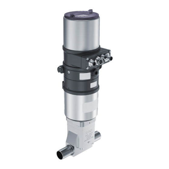
(access for adjust- Type label (Type 2380) ments) Valve body Controller, e.g. Type 8696 Port connection, (type label at rear side) Electrical and control e.g. weld ends air connections Fig. 2: General structure of Type 2380-LB (ELEMENT actuator) Actuator 6.2. Control functions Valve body Port connection, Type 2380 is available with the control functions A (NC) or B (NO): e.g. weld ends Fig. 1: General structure of Type 2380-LA (compact actuator) For connections (compare „Fig. 1“ and „Fig. 2“): see also chapter „8. Installation“ at page 11, where all... -
Page 9: Technical Data
Controller type Orifice Valve type Sealing material Type Body material Media temperatures 0 ... +80 °C Several features of type code (-10 °C ... +150 °C at limited ope- Pressure of medium in bar(g) rating conditions Control air pressure in bar(g) Operating voltage / if applicable communication Media pressure vacuum ... 6 bar(g) ID-No. Serial no. S/N Date of manufacture (encoded) *) m edia pressure max. 4 bar(g), QR code CE (or other) marks up to +134 °C: max. 60 min, 2380-LA: ambient temperature max. +40 °C, up to +150 °C: max. 30 min, 2380-LA: ambient temperature max. +35 °C Fig. 3: Type label 2380 - example english... -
Page 10: Technical Data
Type 2380 Technical Data 7.4. Technical data 7.5. Pneumatical Data Dimensions see data sheet of the suitable Type Control media air, neutral gas 2380 quality classes as per ISO 8573-1: d ust content: quality class 7, Weight 1.4 ... 2.5 kg (Type 2380-LA) water content: quality class 3, 3.2 ... 3.5 kg (Type 2380-LB) oil content: quality class X Materials - m edia valve body: s tainless steel 316L Control air Control air pressure 5.5 ... 7 bar(g) contacting ASME BPE (1.4435 BN2) -
Page 11: Installation
Type 2380 Installation INSTALLATION 8.2. Installation position for Type 2380-LA The device can be installed in any installation position. 8.1. Safety instructions Consider the recommended flow direction (see „Fig. 4“)! DANGER! Leakage detection bores One of the two bores for leakage detection (see „Fig. 4“) Risk of explosion in explosive atmosphere! should be at the lowest point. The other bore should be ▶ Should the device be used in potentially explosive areas, chap- closed to protect the device from outside liquid entry. ter „3“ and the additional instructions for Ex-approved compo- nents must be adhered to. WARNING! The orientation of the actuator (and controller) on the valve body can be Risk of injury from high pressure in the system! varied in steps of 90°. For that purpose... -
Page 12: Installation Position For Type 2380-Lb
The orientation of the leakage detection bores can be varied in steps of 90°. The actuator (and controller) on the valve arrow upward body can be turned by 180°. For that purpose disassemble/assemble the actuator as described in chapter „8.4.2“. Fig. 5: Installation position for self-draining (Type 2380-LA) leakage detection: e xternal (left bore) / internal (right bore) Installation position for self-draining engraved seat and port size It is the responsibility of the plant manufacturer and ope- rator to ensure self-drainage of the device or system. recommended flow direction Fig. -
Page 13: Installation / Connections
„Fig. 11“) Keep the controller assembled to the actuator. 8.4.1. Installation in the pipe system → Remove the O-ring 2 (see „Fig. 8“) from the valve body. → Clean pipelines (sealing material, swarf etc.) → Weld valve body in pipe system. → Before connecting the valve, ensure that the pipelines are Type 2380-LA (compact actuator): flush: support and align the pipelines. → O-ring 2 Connect the valve body to the pipe system; for welded con- nections see next chapter „8.4.2“. O-ring 1 Robust installation Bellow It is the responsibility of the plant manufacturer and operator to ensure a robust installation. The relation of size and length Fig. 8: Detail - valve body - O-rings of the pipe to weight of the device must be considered. -
Page 14: Pneumatic Installation
Type 2380 Installation 8.5. Pneumatic installation Type 2380-LA (compact actuator): Controller (e.g. Type 8696) WARNING! Ports for control air Risk of injury from high pressure in the system! (port 3 and port 1) ▶ Before dismounting the lines and valves, turn off the pres- sure and vent the lines. Actuator with bellow Leakage detection bore (2x) WARNING! Risk of injury from unsuitable connections! Valve body screws (4x) Hoses or pipes which cannot withstand the pressure and (tightening torque of 3.5 Nm) -
Page 15: Electrical Installation
Type 2380 Installation Connection of the control air (see „Fig. 12“) The electrical connection depends on the controller Type 869x → used. Connect the control air to the control air port (1) of the cont- roller Type 869x. The electrical connection of Type 2380 is described in the → Mount an exhaust air line or a silencer to the exhaust air port (3). respective operating instructions of Type 869x controllers on our website www.burkert.com. If used in an aggressive environment, we recommend conveying all free pneumatic connections into a neutral atmosphere with the aid of a pneumatic hose. 8.7. Communication software The PC software “Bürkert Communicator” is designed for communi- cation with Bürkert devices. control air control air (port 1) (port 1) A detailed description for the installation and operation the and... -
Page 16: Start-Up
Type 2380 Start-up → START-UP For Type 8692/93: select the input signal (INPUT). → If necessary, specify additional controller settings (via DIP switches/menu/USB adapter) - see respective operating ins- 9.1. Safety instructions tructions. NOTE! WARNING! CAUTION with using the function SET.FACTORY Risk of injury from improper operation! (reset to factory settings)! Improper operation may result in injuries as well as damage This function does not only reset the settings implemented to the device and the surrounding area. -
Page 17: Cip / Sip
Type 2380 CIP / SIP CIP / SIP MAINTENANCE AND TROUBLESHOOTING The device can be cleaned / sterilized in place. The only media-contacting parts are the valve body and the 11.1. Safety instructions bellow. NOTE! WARNING! Danger of damage to sealings and electronics by Risk of injury from high pressure in the system! overheating! ▶ Before dismounting the lines and valves, turn off the pres- The permitted media temperature of 0 ... +80 °C can be exceeded sure and vent the lines. -
Page 18: Maintenance
Type 2380 Maintenance and troubleshooting 11.2. Maintenance Malfunction Cause / remedial action The device is maintenance-free provided it is used according to Valve does Control air port is not connected correctly: is not connected correctly: → these operating instructions. not open/ Connect control air to port 1. close However, the bellow is subject to natural wear. Control pressure too low: (or rather not → Check the bellow for wear after a maximum of 10 switching See pressure specifications on the type label. completely) cycles or 1 year of operation. -
Page 19: Spare Parts
Type 2380 Spare parts SPARE PARTS Malfunction Cause / remedial action Control quality E.g. caused by changed pressure conditions, 12.1. Safety instructions dissatisfying etc. → Adjust the controller via function X.TUNE WARNING! → Check and adjust the dead band (see also operating instructions for Type 869x) Risk of injury when opening the actuator! → → When control air leakage occurs: see When control air leakage occurs: see The actuator contains a tensioned spring. If the actuator is... -
Page 20: Controller Type 869X
DN10 DN10 00796534 ▶ In case an adjustment of preconfigured customer- Tab. 2: Order table specific settings is required for future deliveries, please contact your Bürkert sales office. Bellows DN1.5, DN3 and DN4 are all combined with a valve body DN4. So a change of the valve orifice 12.3. Spare part sets for Type 2380-LA between DN1.5, DN3 and DN4 can simply be executed by changing the bellow. However, the device then is no The bellow and 2 O-rings are available as a spare part set. longer consistent with the type label. Consider the right size of the bellow according to the type label - This applies accordingly for bellows DN8/DN10 and the see the order table below. valve body DN10. Each set contains: 1x O-ring 20 x 2.5 NOTE! 1x O-ring 52 x 2 Risk of damage to the bellow / malfunction of the device! ▶... -
Page 21: Spare Part Sets For Type 2380-Lb
Spare parts 12.4. Spare part sets for Type 2380-LB If you have any queries, please contact your Bürkert sales office - see chapter „4.1. Contact addresses“. The bellow and the O-ring are available as a spare part set. Con- sider the right size of the bellow according to the type label - see the order table below. 12.5. Replacement of the bellow Each set contains: 12.5.1. Preparations 1x O-ring 40 x 3 Step Task description Illustration Ensure that there is no potential explosive atmosphere. 1x Bellow Ensure that process media pressure is switched off The power supply and the control air supply must be connected in order to trigger the controller. - Page 22 Type 2380 Spare parts 12.5.2. Opening NC-valve (control function A) 12.5.3. Replacement of the bellow Step Task description Illustration Step Task description Illustration Open the valve: Loosen the 4 valve body screws and take off the actuator 8696: press key „1“ Close the valve: key 1 8696: key 1 key 2 NC-valve: press key „2“ key 2 NO-valve: press key „1“ 8694: p ress key „S1/X.TUNE“...
-
Page 23: Disassembly
▶ Observe applicable accident prevention and safety regulati- (where applicable, fix locking wire and earthing cable ons for electrical equipment! again) Risk of injury from improper disassembly! ▶ Disassembly may be carried out by authorized technicians only and with appropriate tools! Risk of injury from unintentional activation of the system and an uncontrolled restart! ▶ Secure system from unintentional activation. 13.2. Disassembly of Type 2380 → Switch off supply voltage and all media supply. → Loosen the electric, fluidic and pneumatic connections. → Remove the device from the system. english... -
Page 24: Transport, Storage, Packaging, Disposal
Type 2380 Transport, Storage, packaging, Disposal TRANSPORT, STORAGE, PACKAGING, DISPOSAL NOTE! TRANSPORT damages! Inadequately protected equipment may be damaged during transport. ▶ During transportation protect the device against wetness and dirt in shock-resistant packaging. ▶ Avoid exceeding or dropping below the allowable storage temperature. ▶ Protect electrical and pneumatic connections from damage using protecting caps. Incorrect STORAGE may damage the device. ▶ Store the device in a dry and dust-free location! ▶ Storage temperature: -20 ... +65 °C DISPOSAL - damage to the environment caused by device components contaminated with media. - Page 25 www.burkert.com...
Need help?
Do you have a question about the 2380 and is the answer not in the manual?
Questions and answers