Burkert 2300 Operating Instructions Manual
2/2-way angle-seat control valve
Hide thumbs
Also See for 2300:
- Operating instructions manual (130 pages) ,
- Quick start manual (55 pages) ,
- Replacement instructions manual (17 pages)

Related Manuals for Burkert 2300


Summary of Contents for Burkert 2300
- Page 1 Type 2300 2/2-way angle-seat control valve 2/2-Wege-Schrägsitzregelventil Vanne de réglage à siège incliné 2/2 voies Operating Instructions Bedienungsanleitung Manuel d‘utilisation...
- Page 2 We reserve the right to make technical changes without notice. Technische Änderungen vorbehalten. Sous réserve de modifications techniques. © Bürkert Werke GmbH & Co. KG, 2008 - 2018 Operating Instructions 1802/09_EU-ML_00805626 / Original DE...
-
Page 3: Table Of Contents
Type 2300 Contents OPERATING INSTRUCTIONS ..........4 INSTALLATION ..............22 Symbols ............... 4 8.1 Safety instructions ............. 22 1.2 Definition of term / abbreviation ........4 8.2 Before installation ............23 8.3 Installation ..............24 INTENDED USE ..............5 8.4 Pneumatic connection ..........28 8.5 Start-up ..............29 BASIC SAFETY INSTRUCTIONS .......... -
Page 4: Operating Instructions
Type 2300 Operating instructions OPERATING INSTRUCTIONS CAUTION! The operating instructions describe the entire life cycle of the device. Warns of a possible danger! Keep these instructions in a location which is easily accessible ▶ Failure to observe this warning may result in a moderately to every user and make these instructions available to every new severe or minor injury. owner of the device. NOTE! The operating instructions contain important safety information! Warns of damage to property! Failure to observe these instructions may result in hazardous ▶... -
Page 5: Intended Use
Type 2300 Intended use INTENDED USE BASIC SAFETY INSTRUCTIONS These safety instructions do not make allowance for any Non-intended use of the angle-seat control valve Type 2300 may • contingencies and events which may arise during the installation. be a hazard to people, nearby equipment and the environment. operation and maintenance of the devices. ▶ The device is designed for the controlled flow of liquid and gaseous media. Operation is possible only in combination • local safety regulations; the operator is responsible for observing with a suitable control unit. these regulations, also with reference to the installation personnel. - Page 6 Type 2300 Basic safety instructions WARNING! General hazardous situations. To prevent injury, ensure that: Risk of injury when opening the actuator! ▶ That the system cannot be activated unintentionally. The actuator contains a tensioned spring. If the actuator is ▶ Installation and repair work may be carried out by authorized opened, there is a risk of injury from the spring jumping out! technicians only and with the appropriate tools. ▶ The actuator must not be opened. ▶ After an interruption in the power supply or pneumatic Risk of injury from moving parts in the device! supply, ensure that the process is restarted in a defined or controlled manner. ▶ Do not reach into openings.
-
Page 7: General Information
Type 2300 General information GENERAL INFORMATION PRODUCT DESCRIPTION Contact address General description Germany The 2/2-way angle-seat control valve Type 2300 is suitable for liquid and gaseous media. Bürkert Fluid Control System Sales Centre It uses neutral gases or air (control media) to control the flow Christian-Bürkert-Str. 13-17 of water, alcohol, oil, fuel, hydraulic fluid, saline solution, lye, D-74653 Ingelfingen organic solvent and steam (flow media). Tel. + 49 (0) 7940 - 10 91 111 The operation of the angle-seat control valve Type 2300 is pos- Fax + 49 (0) 7940 - 10 91 448 sible only in combination with an control unit. Possible control E-mail: info@burkert.com units are: P ositioner Type 8692, 8694 and 8696 International Process controller Type 8693 Contact addresses are found on the final pages of the printed operating manual. Versions You can also find information on the Internet under: There are 2 versions of the angle-seat control valve Type 2300. www.burkert.com • Standard version – without separate Ex type label. -
Page 8: Properties
Type 2300 Product description Properties • Vacuum • Food conformity FDA • Direct installation of the positioners Type 8692 / 8694 / 8696 or • DVGW the process controller Type 8693. • High tightness by self-adjusting packing glands (spindle • ATEX sealing element). 5.3.3 Device versions • Closes tightly when using the PTFE control cone. Pilot pressure • High flow values by the streamlined valve body made of Designs with lower pilot pressure (reduced spring force) are stainless steel. available on request. • Simple and fast replacement of the control cone. Contact your Bürkert sales office or our Sales Centre. • Actuator can be rotated steplessly through 360°. E-mail: info@de.buerkert.com • Maintenance-free under normal conditions. 5.3.1... -
Page 9: Designated Application Area
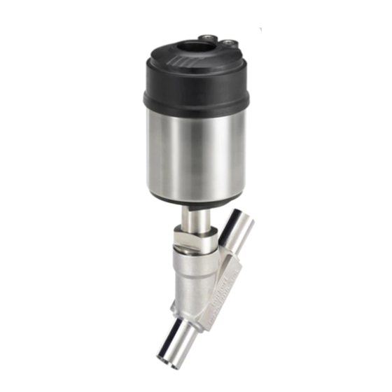
Type 2300 Structure and function Designated application area STRUCTURE AND FUNCTION The operation of the angle-seat control valve Type 2300 Observe the maximum pressure range according to the is possible only in combination with a control unit. type label! Possible control units are: Positioner Type 8692, 8694 and 8696 • Neutral gases and liquids up to 16 bar. Process controller Type 8693 • Steam up to 11 bar absolute / 185 °C for seat seal steel / steel. Steam up to 2.7 bar absolute / 130 °C for seat seal PTFE / steel. Structure • Aggressive media. The angle-seat control valve consists of a pneumatically operated piston actuator, a control cone and a 2/2-way angle- 5.4.1 Application areas seat body. Via a dowel pin, the control cone is modularly coupled to the e.g. P lant construction actuator spindle for quick changeovers. Food processing Chemical engineering For the body, almost any line connections are possible. -
Page 10: Function
Actuator cover WARNING! For control function I – Danger if pilot pressure fails! Actuator body For control function I control and resetting occur pneumatically. If the pressure fails, no defined position is reached. ▶ To ensure a controlled restart, first pressurize the device with pilot pressure, then switch on the medium. Interface actuator/body with wrench Control function A (CFA) flat Normally closed by spring action. Angle-seat body Numbers for indicating the direction of flow Port connection Fig. 1: Angle-seat control valve Type 2300, structure and description english... - Page 11 Type 2300 Structure and function 6.2.2 Flow direction below the seat Control function B (CFB) Normally open by spring action. Depending on the version, the valve is closed against the medium flow with spring force (control function A, CFA) or with pilot pressure (control function B or I, CFB or CFI). As the medium pressure is under the control cone, this pressure contributes to the opening of the valve. WARNING! Medium may be discharged if minimum pilot pressure is too low or medium pressure too high! If the minimum pilot pressure is too low for CFB and CFI or the permitted medium pressure is exceeded, leaks may occur.
-
Page 12: Technical Data
Type 2300 conforms with the EU Directives according to the EU pressure actuator size Declaration of Conformity. Permitted pilot Control function Standards pressure (CF) The applied standards, which verify conformity with the EU Type CE identification Directives, can be found on the EU-Type Examination Certificate and / or the EU Declaration of Conformity. 2300 A 25M PTFE VA Pilot 5,5 - 7bar Tmed -10°C - +130°C Pmed 12bar According to Pressure Equipment Directive the following operating Flow 1 Kvs16 W1XMS conditions must be observed: 00285864 Maximum pressure for compressible fluids Identification Flow direction Date of... - Page 13 Type 2300 Technical data 7.4.1 Temperature ranges 7.4.2 Control medium In conjunction with pneumatic control units (positioner or Medium Actuator Actuator Environ-ment process controllers), pilot air according to DIN ISO 8573-1 must size Seat seal Seat seal material be used: [mm] steel / steel PTFE / steel • Class 3 (for water content) ø 50 • Class 5 (for dust and oil content). -10...+60°C ø 70 -10...+185°C -10...+130°C The specification is described in detail in the operating ø...
- Page 14 Type 2300 Technical data Maximum pilot pressure for valves Operating pressure for control function A without pneumatic control unit Max. sealed Orifice DN Required pilot Actuator size medium [mm] pressure [bar] max. permitted pilot pressure [bar] Actuator size Actuator material pressure ø...
- Page 15 Type 2300 Technical data Pilot pressure for control function B Required minimum pilot pressure depending on medium pressure for circuit function B Pilot pressure[bar] Max. per- Actuator Orifice DN for medium pressure mitted medium ø 50 CFB size [mm] pressure [bar] 0 bar ø...
- Page 16 Type 2300 Technical data ø 70 CFB ø 130 CFB DN25 DN32 Pilot pressure [bar] Pilot pressure [bar] Fig. 4: Pressure graph, actuator ø 70 mm, control function B Fig. 6: Pressure graph, actuator ø 130 mm, control function B ø...
-
Page 17: Flow Values And Characteristics
Type 2300 Technical data Flow values and characteristics Flow values for DN20 Stroke Stroke Flow values for DN15 Kv value [m Kv value [m Stroke Stroke Kv value [m Kv value [m 0.26 0.27 0.16 0.17 0.22 10.0 Tab. 8: Flow values for DN20 Tab. - Page 18 Type 2300 Technical data Flow values for DN25 Flow values for DN32 Stroke Stroke Stroke Stroke Kv value [m Kv value [m Kv value [m Kv value [m 0.34 11.5 0.43 13.8 0.36 13.0 0.52 16.4 0.62 14.2 0.82 19.2 15.4...
- Page 19 Type 2300 Technical data Flow values for DN40 - Actuator size ø 90 Flow values for DN40 - Actuator size ø 130 Stroke Stroke Stroke Stroke Kv value [m Kv value [m Kv value [m Kv value [m 0.47 21.5 0.48...
- Page 20 Type 2300 Technical data Flow values for DN50 - Actuator size ø 90 Flow values for DN50 - Actuator size ø 130 Stroke Stroke Stroke Stroke Kv value [m Kv value [m Kv value [m Kv value [m 0.85 28.6 0.87...
-
Page 21: General Technical Data
Type 2300 Technical data General technical data Flow values for DN65 - Actuator size ø 130 Stroke [%] Kv value [m Stroke [%] Kv value [m Control functions (CF) The valve seat is always closed against the medium flow 58.0 67.0 Control function A N ormally closed by spring action 75.0 Control function B N ormally open by spring action 20.0... -
Page 22: Installation
Type 2300 Installation INSTALLATION Spindle 1.4401 / 1.4404 Spindle guide 1 .4401 / 1.4404 / 316L Safety instructions Connections DANGER! Pilot air port p repared for direct connection Danger – high pressure in the equipment! Medium connection T hreaded port: G ½ – G 2 ½ ▶ Before loosening the lines and valves, turn off the pressure (NPT, RC on request) and vent the lines. Welded connection: as per EN ISO 1127 (ISO 4200), DIN 11850 R2 WARNING! Other connections on request Media Risk of injury from improper installation! ▶... -
Page 23: Before Installation
Type 2300 Installation Remove the control unit from the actuator (if present): CAUTION! → Clamp the valve body in a holding device. Risk of injury due heavy devices! → Loosen the fastening screws (2x). ▶ During transport or during assembly, a heavy device may fall → Remove the control unit upwards. and cause injury. ▶ Do not transport, install or remove heavy devices without the aid of a second person and using suitable auxiliary equipment. ▶ Use appropriate tools. Fastening screw Control unit (2x) Before installation • The angle-seat control valve can be installed in any installation position, preferably with the actuator in upright position. Actuator • Before connecting the valve, ensure the pipelines are flush. • Make certain the flow direction is correct (Flow direction Fig. 16: Disassembly the control unit always below seat). -
Page 24: Installation
Type 2300 Installation Installation → Unscrew the actuator from the valve body. Exhaust air port Install collet: CFA, CFB WARNING! Pilot air port CFI Risk of injury from improper installation! Assembly with unsuitable tools or non-observance of the tight- ening torque is dangerous as the device may be damaged. Pilot air port ▶ For installation use an open-end wrench, never a pipe CFA, CFB, CFI Actuator wrench. ▶ Observe the tightening torque (see “Tab. 16: Tightening Nipple Flats for open- torques of valve body / nipples”). end wrench Dirt trap for devices with authorisation in accordance with DIN... - Page 25 Type 2300 Installation 8.3.1 Installation of the valve body NOTE! Welded bodies Damage to the seat seal or the seat contour! ▶ When installing the actuator, ensure that the valve is in open → Weld valve body in pipeline system. position. Other body versions → Control function A pressurize the pilot air port 1 with com- → Connect body to pipeline. pressed air (5 bar): valve opens. 8.3.2 Install actuator (welded body) → Screw actuator into the valve body.
- Page 26 Type 2300 Installation 8.3.3 Install control unit → Push the control unit, without turning it, onto the actuator until no gap is visible on the form seal. Before installation, check the position of the ports on the control unit and, if required, align the actuator. NOTE! Description see chapter “8.3.4 Rotating the actuator”. Too high torque when screwing in the fastening screw does not ensure protection class IP65 / IP67! → Remove collet from pilot air port 1. ▶ The fastening screws may be tightened to a maximum → Check that the O-rings are correctly positioned in the pilot air torque of 1.5 Nm only. ports. → Align the puck holder and the control unit until →...
- Page 27 Type 2300 Installation 8.3.4 Rotating the actuator Actuator with hexagon: → Place suitable open-end wrench on the hexagon of the The position of the connections can be aligned steplessly by actuator. rotating the actuator through 360°. → Rotate counter-clockwise (as seen from below) to bring the Only the entire actuator can be rotated. The control unit actuator into the required position. cannot be rotated contrary to the actuator. Actuator without hexagon: → Fit special wrench exactly into the wrench contour on the NOTE! underside of the actuator. Damage to the seat seal or the seat contour! → Rotate clockwise (as seen from below) to bring the actuator ▶ When rotating the actuator, ensure that the valve is in open into the required position.
-
Page 28: Pneumatic Connection
Type 2300 Installation Pneumatic connection 8.4.1 Connection of the control medium → Connect the control medium to the pilot air port (1) DANGER! (3 – 7 bar; instrument air, free of oil, water and dust). Danger – high pressure in the equipment! → Fit the exhaust line or a silencer to the exhaust air port (3) ▶ Before loosening the lines and valves, turn off the pressure and, if available, to the exhaust air port (3.1). and vent the lines. If used in an aggressive environment, we recommend WARNING! conveying all free pneumatic connections into a neutral atmosphere with the aid of a pneumatic hose. Risk of injury from unsuitable connection hoses! Hoses which cannot withstand the pressure and temperature range may result in hazardous situations. -
Page 29: Start-Up
Type 2300 Electrical control unit Start-up ELECTRICAL CONTROL UNIT After installing the device, run the X.TUNE function. This function The valve Type 2300 can be combined with following control presets the control parameters. units: • Type 8692 Positioner Description – see operating instructions for the control. • Type 8694 Positioner • Type 8696 Positioner • Type 8693 Process controller Removal DANGER! The electrical connection of the pilot valve or the control unit is described in the respective operating instruc- Risk of injury from discharge of medium and pressure! -
Page 30: Maintenance, Cleaning
Type 2300 Maintenance, cleaning MAINTENANCE, CLEANING WARNING! For control function I – Danger if pilot pressure fails! 10.1 Safety instructions For control function I control and resetting occur pneumati- DANGER! cally. If the pressure fails, no defined position is reached. Danger – high pressure in the equipment! ▶ To ensure a controlled restart, first pressurize the device with ▶ Before loosening the lines and valves, turn off the pressure pilot pressure, then switch on the medium. and vent the lines. Risk of injury from moving parts in the device! Risk of injury due to electrical shock! ▶... -
Page 31: Replacing The Wearing Parts
Type 2300 Maintenance, cleaning 10.3 Replacing the wearing parts The replacing of the wearing parts is described in chapter “10.3 Replacing the wearing parts”. 10.3.1 Replacing the control cone set Visual inspection: The control cone set consists of Perform regular visual inspections according to the application • Control cone • Dowel pin conditions: • Graphite seal • Lubricant → Check media connections for leaks. → Check release bore on the tube for leaks. Before the control cone set can be replaced, the actuator must be removed from the valve body. DANGER! Release bore Risk of injury from discharge of medium and pressure! It is dangerous to remove a device which is under pressure Fig. - Page 32 Type 2300 Maintenance, cleaning Removing the actuator from the valve body Replace the control cone set → Clamp the valve body in a holding device (applies only to valves which have not yet been installed). Seal NOTE! Damage to the seat seal or the seat contour! Spindle ▶ When removing the actuator, ensure that the valve is in open position. Dowel pin → Control function A: Without unit control: pressurize the pilot air port 1 with com- Control cone pressed air (5 bar): valve opens.
- Page 33 Type 2300 Maintenance, cleaning → Support control cone on the cylindrical part with the aid of a prism or something similar. → Put on dowel pin and carefully knock in with a hammer. → Position the dowel pin in the centre of the spindle axis. Pilot air port Install the actuator (with control unit) on the valve body Fig. 27: Connections → Check the seal and if required, replace it. Tightening torques of valve body / nipples WARNING! Tightening torques [Nm] Danger if incorrect lubricants used! 45 ±3...
- Page 34 Type 2300 Maintenance, cleaning 10.3.2 Replacing the packing gland DANGER! The seal set for the packing gland contains Risk of injury from discharge of medium and pressure! SP10 / SP14 It is dangerous to remove a device which is under pressure due to the sudden release of pressure or discharge of medium. • 1 support ring ▶ Before removing a device, switch off the pressure and vent the • 5 chevron seals lines. • 2 or 3 pressure rings WARNING! • 1 pressure spring • 1 seal Risk of injury if the wrong tools are used! •...
- Page 35 Type 2300 Maintenance, cleaning Removing the actuator from the valve body Removing the control cone set → Clamp the valve body in a holding device Seal (applies only to valves which have not yet been installed). Spindle NOTE! Damage to the seat seal or the seat contour! Dowel pin ▶ When removing the actuator, ensure that the valve is in open position. Control cone → Control function A: Without unit control: pressurize the pilot air port 1 with com- Fig.
- Page 36 Type 2300 Maintenance, cleaning Replacing packing gland PEEK spindle guide (series production status up to April 2012): Packing gland tube → Unscrew the spindle guide with the aid of the installation Packing gland wrench and an open-end wrench. 13) VA spindle guide VA spindle guide (Series production status since April 2012): → Unscrew spindle guide using a modified socket wrench 13) Spindle SP22: → Unscrew the VA spindle guide with the aid of an open-end wrench.
- Page 37 Type 2300 Maintenance, cleaning WARNING! If the valve features a PEEK spindle guide (series pro- duction status up to April 2012), we recommend replacing Risk of injury from parts jumping out! it with a VA spindle guide (see “Tab. 25: VA spindle guide for packing gland”, page 42) When the spindle opening is exposed, the individual parts of the packing gland are pressed out at an undefined speed when → Grease thread of the spindle guide (Klüber paste UH1 the pilot air ports is pressurized. 96-402). ▶ Before pressurizing with control air, safeguard the ambient area → Screw spindle guide back in using the installation tool. of the discharge opening (e.g. place spindle on a firm base). Observe torque (see “Tab. 19: Tightening torques of spindle”)! Pilot air port Support ring Pilot air port Upper Fig.
- Page 38 Type 2300 Maintenance, cleaning Tightening torques of spindle Support ring Spindle Orifice Material of Tightening diameter body spindle guide torque [Nm] Upper chevron seals 10 mm PEEK Upper pressure ring(s) 1.4401 / 1.4404 / 316L 20 – 25 Pressure spring 14 mm PEEK 1.4401 / 1.4404 Lower pressure ring / 316L 32 – 50 Lower chevron seals 22 mm 1.4401 / 1.4404 Tab.
- Page 39 Type 2300 Maintenance, cleaning Install the actuator (with control unit) on the valve body → Check the seal and if required, replace it. Pilot air port WARNING! Fig. 36: Connections Danger if incorrect lubricants used! Unsuitable lubricant may contaminate the medium. In oxygen Tightening torques of valve body / nipples applications there is a risk of an explosion! ▶ In specific applications, e.g. oxygen or analysis applications, Tightening torques [Nm] use appropriately authorised lubricants only.
-
Page 40: Malfunctions
Type 2300 Malfunctions MALFUNCTIONS Malfunction Remedial action Valve is not Dirt between seal and valve seat Malfunction Remedial action sealed. → Installing dirt trap Actuator does Pilot air port interchanged Seat seal worn not switch. CFA: Connecting pilot air port 1 → Installing a new control cone CFB: Connecting pilot air port 1 Flow direction reversed Pilot air port 1: Open See direction arrow on the body. Pilot air port 2: Close Medium pressure too high Pilot pressure too low See pressure specifications on the type See pressure specifications on the type label. label. Pilot pressure too low Medium pressure too high See pressure specifications on the type See pressure specifications on the type label. -
Page 41: Replacement Parts
Type 2300 Replacement parts REPLACEMENT PARTS Control cone set Actuator size Order no. WARNING! [mm] PTFE / Steel Steel / Steel Risk of injury when opening the actuator! ∅ 50, ∅ 70 170 315 170 322 The actuator contains a tensioned spring. If the actuator is ∅ 50, ∅ 70 170 316 170 323 opened, there is a risk of injury from the spring jumping out! ▶... - Page 42 Type 2300 Replacement parts VA spindle guide for packing gland 1 S eal 2 C ontrol cone Spindle ∅ Actuator size Order no. Control cone set 3 Dowel pin ∅ 50, ∅ 70 246 577 4 S ealing set for 20 / 25 ∅ 50, ∅ 70 246 578 packing gland ∅...
-
Page 43: Installation Tools
Type 2300 Packaging, transport, storage 12.2 Installation tools PACKAGING, TRANSPORT, STORAGE Only for PEEK spindle guide: Installation wrench for packing gland NOTE! (Series-production status until April 2012) Transport damages! Installation wrench Order no. Inadequately protected equipment may be damaged during Spindle diameter 10 mm 665 700 transport. Spindle diameter 14 mm 665 701 • During transportation protect the device against wet and dirt Tab. 26: Installation wrench for PEEK spindle guide in shock-resistant packaging. - Page 45 www.burkert.com...
Need help?
Do you have a question about the 2300 and is the answer not in the manual?
Questions and answers