Table of Contents

Related Manuals for LEMKEN Karat 9 K


Summary of Contents for LEMKEN Karat 9 K
- Page 1 Operating Instructions Intensive Cultivators Karat 9 K - en - Item no. 175_4353 BA_03/08.15 LEMKEN GmbH & Co. KG Weseler Straße 5, 46519 Alpen / Germany Telephone +49 28 02 81 0, Fax +49 28 02 81 220 lemken@lemken.com, www.LEMKEN.com...
- Page 3 However, this brief instruction is not a substitute for thorough study of the operating instructions. These operating instructions will help to familiarise you with the LEMKEN GmbH & Co. KG device and the options available for using it.
- Page 4 Remember that you should only use genuine LEMKEN spare parts. Reproduction parts have a negative influence on the function of the device, have a shorter ser- vice life and present risks and hazards that cannot be estimated by LEMKEN GmbH & Co. KG. They also increase the maintenance costs.
-
Page 5: Table Of Contents
Contents General information ....................9 Liability ........................... 9 Guarantee ........................9 Copyright ........................10 Optional accessories ....................10 Type plate ........................11 Symbols used in the Operating Instructions ............13 ... - Page 6 Applicable rules and regulations ................24 Operation on public highways ................... 25 3.9.1 Lighting system and identification ................25 3.9.2 Requirements of the tractor ..................25 3.9.3 Axle loads ........................26 ...
- Page 7 Preparation of the Tractor ..................38 Tyres ..........................38 Lift Rods ........................38 Check chains/stabilisers on the three-point linkage ..........38 Required power sources..................... 38 Required hydraulic equipment ................... 39 ...
- Page 8 Operation ......................... 59 11.1 Working depth of tines....................60 11.1.1 General information ....................60 11.2 Lowering depth of the rollers ..................61 11.2.1 Hydraulic working depth adjustment ............... 61 11.2.2 Calibrating the working depth .................
- Page 9 Put the implement out of operation ............... 91 14.1 Shutting down the implement in an emergency ............91 14.2 Disposal ........................91 Maintenance and repairs ..................92 15.1 Special safety instructions ..................92 ...
- Page 10 15.9 Air pressure of tyres ....................106 15.10 Scrapers ........................107 15.10.1 Flex ring roller scrapers ..................107 Technical Data ....................... 108 Noise, Airborne Sound ..................109 Notes ........................109 ...
-
Page 11: General Information
Co. KG, in particular Section IX, shall apply. Liability. In line with the dimensions cited in these conditions the LEMKEN GmbH & Co. KG shall not be held liable for any personal or material damage, when such damage is caused by one or more of the following reasons: ... -
Page 12: Copyright
Infringements will result in a claim for damages. Optional accessories LEMKEN implements may be equipped with various accessories. The operating instructions below describe both series components and optional accessories. Please note: These accessories will vary depending on the type of equipment. -
Page 13: Type Plate
General information Type plate The implement carries a type plate. The type plate can be found at front right on the implement. The operating instructions may apply to different implement types or variants of the implement. The operating instructions indicate infor- mation which only applies to a specific im- plement type or a specific variant of the implement. - Page 14 General information 1 Series 2 Type designation 3 Serial number 4 Year of manufacture 5 Permissible drawbar load [kg] 6 Permissible axle load [kg] 7 Permissible gross weight [kg] 8 Company logo and address 9 CE marking (only within the European Union) 10 Name of manufacturer 11 Type, variant, version 12 Type approval date...
-
Page 15: Symbols Used In The Operating Instructions
Symbols used in the Operating Instructions SYMBOLS USED IN THE OPERATING INSTRUCTIONS Hazard classes The following symbols are used in the Operating Instructions for particularly im- portant information: DANGER Denotes an imminent hazard with high risk, which will result in death or severe physical injury, if not avoided. -
Page 16: Indication Of Passages
Symbols used in the Operating Instructions Indication of passages The following symbols are used for particular passages in the operating instruc- tions: Indicates work steps Indicates enumerations... -
Page 17: Safety Measures And Precautions
Safety measures and precautions SAFETY MEASURES AND PRECAUTIONS General safety instructions for the operator are specified in the chapter entitled «Safety measures and precautions». At the start of some main chapters the safety instructions, which refer to all work to be carried out in this chapter, are listed to- gether. -
Page 18: Safety Features Of The Device
Safety measures and precautions Safety features of the device To protect the operator and the device, the device is equipped with special safety features in accordance with country specific requirements. Always keep all safety devices in working order. Warning signs with light Guide rod for rollers Hydraulic fold-out lock Protective tarpaulin... -
Page 19: Safety And Warning Signs
Safety measures and precautions Safety and warning signs 3.4.1 General information The implement features all equipment which ensures safe operation. If hazardous areas could not be completely secured with respect to operational safety, warning signs are affixed which indicate these re- sidual risks. -
Page 20: Meaning Of Warning Signs
Safety measures and precautions 3.4.3 Meaning of warning signs Please familiarise yourself with the meaning of the warning signs. The following explanations provide detailed information. Please read and observe the operating in- structions and safety instructions before starting up the implement for the first time. Before carrying out maintenance or repair work, switch off the engine and remove key. -
Page 21: Meaning Of Other Symbols
Safety measures and precautions Keep out of the folding area of the device. The front axle of the tractor must always be loaded with at least 20% of the trac- tor's curb weight. When the three-point power lift is activat- ed, stay outside of the lifting range of the three-point suspension. -
Page 22: Special Safety Instructions
Safety measures and precautions Special safety instructions Risk of injury due to non-observance of the currently valid occupational safety guidelines If the currently valid occupational safety guidelines are bypassed WARNING or safety equipment is rendered unusable when handling the de- vice, there is a risk of injury. - Page 23 Safety measures and precautions Risk of injury when freeing casualties When rescuing people trapped or injured by the device, there is a risk of additional serious injury to the casualty if the hydraulic con- nections were not connected according to their colour coding as described in the section entitled "Required hydraulic equipment".
-
Page 24: Danger Areas
Safety measures and precautions Danger areas 3.6.1 Danger areas during implement operation Moving danger area The danger area around the implement moves with the implement during operation. The danger area includes the area extending across the entire width (a) of the implement in the direction of WARNING travel. -
Page 25: Danger Areas When Folding And Unfolding
Safety measures and precautions 3.6.2 Danger areas when folding and unfolding Risk of impact and crushing from moving implement compo- nents There is a risk of impact or crush injuries from moving implement components. The danger area includes the area extending across the entire width of the implement (a). -
Page 26: Residual Risks
Safety measures and precautions Residual risks Residual risks are particular hazards which occur when handling the device and which cannot be eliminated despite a design in accordance with safety require- ments. Residual risks are not usually obvious and may be the source of a potential injury or health hazard. -
Page 27: Operation On Public Highways
Safety measures and precautions Operation on public highways 3.9.1 Lighting system and identification A proper lighting system, identification and equipment must be on the device if it is to be transported on public roads. Further information can be requested from the appropriate authorities. -
Page 28: Axle Loads
Safety measures and precautions 3.9.3 Axle loads Implements mounted to the front and rear three-point linkage must not result in the following being exceeded: permissible gross weight of tractor, permissible axle loads of tractor, the tractor's tyre load-carrying capacities. The tractor's front axle must always be loaded with at least 20 % of the tractor's curb weight. - Page 29 Safety measures and precautions Data from tractor operating instructions Take the following data from your tractor's operating instructions: Abbreviation Data Tractor kerb weight (kg) _______ kg Front axle load (kg) of empty tractor _______ kg Rear axle load (kg) of empty tractor _______ kg Data from implement operating instructions ...
- Page 30 Safety measures and precautions Data to be determined through remeasuring are Determine the following data through remeasuring: Abbreviation Data Distance (m) between centre of gravity for front _______ m mounting implement or front weight and centre of front axle Tractor wheelbase (m) _______ m Distance (m) between centre of rear axle and centre...
- Page 31 Safety measures and precautions Calculation of actual front axle load T V tat x (a + b) + T x b – G x (c + d) V tat Enter the value for the calculated actual front axle load and the permissible front axle load as given in the tractor's operating instructions into the table.
-
Page 32: Check Before Departure
Safety measures and precautions 3.9.4 Check before departure Before driving with the device lifted off, lock the control lever, otherwise it may drop and the device may be unintentionally lowered. Check that the fold-out safety device for the side parts is locked correctly! ... -
Page 33: Operating The Device Safely
Safety measures and precautions The operating instructions are an important component of the device. Ensure that the operating instructions are always ready available at the installa- tion location of the device and are kept for the entire service life of the device. ... -
Page 34: Personnel Selection And Qualifications
Safety measures and precautions When actuating the external control for the three-point attachment, do not walk between the tractor and device. It is prohibited to be within the hazardous area of the machine and to climb up on the implement while it is operating. In the wider operating range of the device there is a risk of injury, e.g. -
Page 35: Handing Over The Implement
Handing over the Implement HANDING OVER THE IMPLEMENT As soon as the implement is delivered, ensure that it corresponds with the order package. Also check the type and completeness of any supplied accessories. When the device is handed over, your dealer will explain how it works. ... -
Page 36: Structure And Function
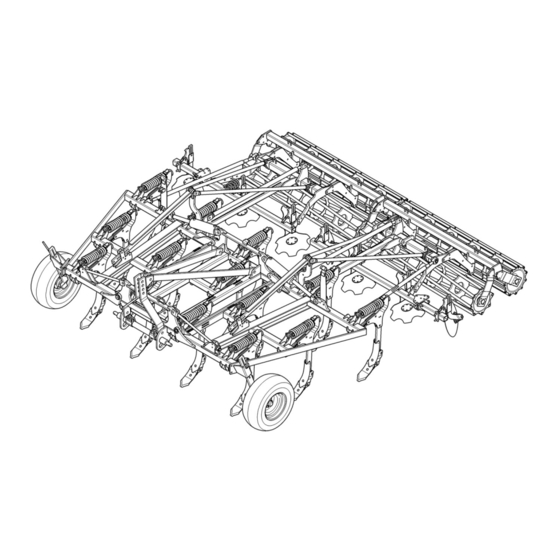
Structure and function STRUCTURE AND FUNCTION Overview 1 Headstock 2 Frame 3 Tines 4 Working depth adjustment for tines 5 Automatic overload safety device for tines 6 Hollow discs (serrated) 7 Outer discs 8 Roller 9 Hydraulic transport locking device 10 Depth control wheels 11 Cross shaft 12 Lighting equipment (not shown) -
Page 37: Function
Structure and function Function 5.2.1 Three-point tower The three-point tower with top link pin and drawbar comply optionally with catego- ry 3, 3N or 4N in accordance with ISO 730. Drawbar L3/Z3 complies with category 3. Drawbar L2/Z3 complies with category 3N. Drawbar L3/Z4 complies with category 4N. -
Page 38: Automatic Overload Safety Device For The Tines
Structure and function 5.2.5 Automatic overload safety device for the tines The automatic overload safety device for the tines protects the frame and the tines from overload. The spring of the overload safety device has been preset. This set- ting must not be changed. 5.2.6 Hollow discs The hollow discs protected by shear bolts are serrated and level the soil behind the tines. -
Page 39: Feeler Wheels
Structure and function 5.2.12 Feeler wheels Feeler wheels are used to improve the depth guide. 5.2.13 Lighting system The lighting system contributes significantly to increasing the safety of the imple- ment in road traffic. -
Page 40: Preparation Of The Tractor
Preparation of the Tractor PREPARATION OF THE TRACTOR Tyres The pressure - especially in the rear tractor tyres - must be equal. In heavy condi- tions it may be necessary to add wheel weights and/or water ballast. (See manu- facturer’s instructions). Lift Rods Adjust lift rods to equal length. -
Page 41: Required Hydraulic Equipment
Preparation of the Tractor Required hydraulic equipment The device is supplied as standard with separate hydraulic connections for each consumer. The protective caps for the hydraulic connections are colour-coded and the hydraulic connections themselves are alphanumerically coded. For operation of the individual hydraulic devices listed below, the tractor must be equipped with the following double-acting control units: Tractor/Device Single-acting... -
Page 42: Three-Point Linkage
Preparation of the Tractor Three-point linkage Danger to life if three-point linkage category is too small If a drawbar or a top link pin is used with a category that is too small, these components may be overloaded and break. As a re- sult, the implement may fall down and injure or kill people in the DANGER immediate vicinity. - Page 43 Preparation of the Tractor Working width 400 cm 500 cm Drawbar Category 3 Category 3 Drawbar Category 3N Category 3N Drawbar Category 4N Category 4N Upper control link Category 3 (approx. Ø 32 mm) Category 3 (approx. Ø 32 mm) The maximum permissible tractor outputs and dimensions as per ISO 730-1 for the corresponding category are available in the following table.
-
Page 44: Hydraulic System
Preparation of the Tractor Hydraulic system 6.7.1 Transport Lowering the three-point linkage CAUTION The device may be damaged if the three-point linkage of the trac- tor is lowered due to an incorrect setting or operation. For transport always switch the hydraulic system of the tractor to "position control". -
Page 45: Preparations On Implement
Preparations on implement PREPARATIONS ON IMPLEMENT Final assembly For transportation-specific reasons, the implement is not always delivered in a ful- ly-assembled condition. Use the implement only when the implement has been fully assembled and a functional check has been performed. -
Page 46: Attaching The Implement
Attaching the implement ATTACHING THE IMPLEMENT Risk of injury when coupling the device WARNING There is a risk of body parts being crushed between the tractor and device The tractor must be secured against unintentionally rolling away. Never actuate the hydraulic system of the tractor if there are people between the tractor and device. - Page 47 Attaching the implement...
-
Page 48: Coupling
Attaching the implement Danger to life due to unsecured connection between lower link and drawbar If the connection between lower link and drawbar is not secured, the pintle of the drawbar may slip out. DANGER As a result, the implement may fall down and injure or kill people in the immediate vicinity. - Page 49 Attaching the implement Now drive up to the implement and con- nect the lower links (2) of the tractor to the drawbar (3). Secure the drawbar (3) with the safety equipment (4). See also the tractor manufacturer's operating instructions. ...
-
Page 50: Drawbar
Attaching the implement Drawbar The drawbar (1) can be mounted on the device at two heights = draw point posi- tions. The picture shows the drawbar (1) in the upper mounting position = low draw point. The bores (2) are used to hold the drawbar (1) in the lower mounting position = high draw point. -
Page 51: Upper Control Link
Attaching the implement Upper control link Risk of injury from unsecured upper control link pin If the upper control link pin is not secured, it may slip out or get CAUTION lost. As a result, the implement may fall down or be damaged. ... -
Page 52: Retracting/Extending The Side Sections
Retracting/extending the side sections RETRACTING/EXTENDING THE SIDE SECTIONS Risk of accident due to incorrect retraction of the side sections Incorrect retraction of the side sections will result in accidents if there are people in the slewing and folding area of the side section or if there are high-voltage lines in the slewing and folding area of DANGER the side sections. -
Page 53: Retracting
Retracting/extending the side sections Retracting Before retracting the side sections (1), lift out the device all the way. Retract the side sections (1) of the im- plement. This is done by operating the control unit in the retract position (1st pressure position). The side parts are retracted through the folding cylinder (2) up to the end position. -
Page 54: Extension
Retracting/extending the side sections Extension Risk of accident due to incorrect extension of the side sec- tions Incorrect extension of the side sections will result in accidents if there are people in the hazardous areas of the side section or if there are high-voltage lines in the slewing and folding area of the side sections. - Page 55 Retracting/extending the side sections Remove the protective devices with lighting. Before extending the side sections (1), lift out the implement all the way. Release the control unit of the tractor for the folding cylinders (2). Then switch the control unit to the retract position (1st pressure position) and then quickly to the extend position (2nd pres- sure position).
-
Page 56: Driving On Public Highways
Driving on public highways DRIVING ON PUBLIC HIGHWAYS 10.1 General information A proper lighting system, identification and equipment must be on the implement, if it is to be transported on public roads. The country-specific valid laws and regu- lations pertaining to driving on public roads must be observed. 10.2 Preparation for driving on public roads Before commencing a journey on public roads, the following components and... - Page 57 Driving on public highways Before travelling on public roads, cover the tines (1) of the side parts with the protec- tive devices (2). Retract the side sections. See "Retract- ing", page 50. Slide the protective device into the bracket (3).
-
Page 58: Lighting System
Driving on public highways When working, the transport protection can be positioned on the frame in the flat steel bars and secured using the tightening straps. 10.5 Lighting system The lighting system must be supplied with power. -
Page 59: Edging Discs
Driving on public highways 10.6 Edging discs For travel on public roads, the edging discs (3) must be swivelled backwards if the maximum permitted transport height of 4 m is exceeded. Release the pin (5) and pull it out. ... -
Page 60: Transport Dimensions
Driving on public highways 10.7 Transport dimensions Danger due to implement being raised too high WARNING The height of the retracted implement may be too high. This means there is an increased danger under bridges, driveways and high-voltage lines Ensure that the transport height of 4 m is not exceeded. ... -
Page 61: Operation
Operation OPERATION Read and follow the information in the section entitled "Safety and protection measures". CAUTION The implement may only be used, maintained and repaired by people who are familiar with it and who are aware of the haz- ards involved. -
Page 62: Working Depth Of Tines
Operation 11.1 Working depth of tines 11.1.1 General information The working depth of the implement can be adjusted by approx. 5 to 25 cm. A precision adjustment can be made using the adjustment devices (1) with adjustment stops (2) and spacer plates (6). A rough setting can be conducted through shifting the adjustment stops (2) on the strut (3) with the aid of linch pins (4). -
Page 63: Lowering Depth Of The Rollers
Operation 11.2 Lowering depth of the rollers To prevent the roller from being lowered too far when lifted out, the counter stop (9) must be in the working position as near as possible to the stop (7). Lower the implement to the working po- sition. -
Page 64: Calibrating The Working Depth
Operation 11.2.2 Calibrating the working depth The working depth must be recalibrated if roller depth control has altered, e.g. as a result of oil leakage from the hydraulic rams. Fully raise the front and rear of the im- plement. It is best to do this on the head- land. -
Page 65: Feeler Wheel
Operation 11.3 Feeler wheel Risk of injury due to unsecured feeler wheel If the guide pin and cam lever are simultaneously removed, the WARNING feeler wheel is no longer held in place and can slide downwards when unsecured. This can result in crushing and foot injuries. ... -
Page 66: Working Depth Of Hollow Discs
Operation 11.4 Working depth of hollow discs Loss of components DANGER If the guide pins are not secured, they can fall out due to vibra- tions in operation. This can result in components being lost during operation and transportation and can cause accidents or damage to the implement and the tractor. -
Page 67: Working Depth Of The Edge Discs
Operation 11.5 Working depth of the edge discs Loss of components DANGER If the guide pins are not secured, they can fall out due to vibra- tions in operation. This can result in components being lost during operation and transportation and can cause accidents or damage to the device and the tractor. -
Page 68: Adjusting The Side Shields
Operation 11.6 Adjusting the side shields Risk of injury from worn side shields Worn and abraded side shields may have sharp edges which can WARNING cause cut injuries to the hands. Take care when handling worn and abraded side shields. ... -
Page 69: Share Position
Operation 11.7 Share position Risk of injury when shear bolt is removed WARNING The tine can swing freely when the shear bolt is removed. This can cause crush injuries to the fingers in the area around the tine pocket. Replace any shear bolts that have been removed as soon as possible. - Page 70 Operation The share position is adjusted by moving the shear bolt (2). Shallow share position Insert the shear bolt through the hole (4) in the tine pocket (3) and the hole (5) in the tine (1). Steep share position ...
- Page 71 Operation All the tines must be set to the same posi- tion. Raise the implement a few centimetres. Secure the implement to prevent it from dropping. Loosen the nut on the shear bolt (2) and remove it. ...
-
Page 72: Automatic Overload Protection
Operation 11.8 Automatic overload protection 11.8.1 Tines Risk of fatal injury due to high spring force If the tine, the hollow disc or the edging disc is actuated and has DANGER still not been moved back into the working position, it can sudden- ly rebound into the working position with great force and at high speed. -
Page 73: Hollow Discs
Operation 11.8.2 Hollow discs Risk of fatal injury due to high spring force If the tine, the hollow disc or the edging disc is actuated and has DANGER still not been moved back into the working position, it can sudden- ly rebound into the working position with great force and at high speed. -
Page 74: Edge Discs
Operation 11.8.3 Edge discs Danger to life due to high spring energy If the tine, the hollow disc or the edge disc is actuated and has still DANGER not been moved back into the working position, it can suddenly rebound into the working position with great force and at high speed. -
Page 75: Rollers
The implement can be fitted with different types of roller. The rollers control the working depth of the implement. The degree of reconsolidation or crumbling is de- termined by the type of roller used. Roller type Karat 9 K / KU Tube bar roller RSW 540 RSW 600... -
Page 76: Flex Ring Roller
Operation 11.9.2 Flex ring roller The flex ring roller is fitted with scrapers. The scrapers can be installed in two posi- tions. Flex ring rollers are supplied with the scrapers in the lower position (2) (top hole in the scraper (3)). On light soils, scrapers in the lower posi- tion may severely impede the flow of soil. -
Page 77: Blade Rollers
Operation 11.9.3 Blade rollers CAUTION Loss of components If the guide pins are not secured, they can fall out due to vibra- tions during operation. The guide pins must always be secured by split rings. Working depth of blades The working depth of the blades (6) is ad- justed using the guide pins (3) as follows: ... - Page 78 Operation Movement of blades The upward movement of the blades (6) is limited using the guide pins (5). If neces- sary, slight movement upwards can be permitted. Position of blades The blades are generally screwed onto the blade frame (7) in the front position. In case of wear, the blades (6) can be moved backwards.
-
Page 79: Pressure Load On Rollers - Intake Behaviour
Operation 11.9.4 Pressure load on rollers - Intake behaviour The pressure load on the rollers is determined by the position of the upper control link and the mounting position of the drawbar. The hydraulic system of the tractor must be switched to the float position. Drawbar The drawbar should always be mounted in the upper mounting position. - Page 80 Operation The lower the upper control link is mounted on the implement's three-point tower, the greater the pressure load on the rollers – resulting in better intake be- haviour. The higher the upper control link is mounted on the implement's three-point tower, the lower the pressure load on the rollers –...
- Page 81 Operation Upper control link mounting position Risk of injury from unsecured upper control link pin If the upper control link pin is not secured, it may slip out or get lost. CAUTION As a result, the implement may fall down or be damaged. As a result, people in the immediate vicinity may be injured.
- Page 82 Operation Drawbar mounting position The mounting position of the drawbar (1) with unhitched implement can be changed as follows: Remove the nuts (3) on the bolts (4) of the two locking pieces (5). Pull the drawbar (1) as far as the middle out of the bores of the rail plates (6).
- Page 83 Operation Push the locking pieces (5) onto the drawbar (1). Ensure that the side with the support surface (7) is facing the rail plate (6). Push the drawbar (1) through the bores until the two ends of the drawbar (1) on the left and right are the same distance from the rail plates (6).
-
Page 84: Turning At The Headland
Operation 11.10 Turning at the headland DANGER Risk of damage to components If the implement is not fully raised, there is a danger that compo- nents may be damaged during an improper turn at the headland. Before turning at the headland the implement must be completely raised before turning-in to avoid any damage to the implement. -
Page 85: Uncoupling The Implement
Uncoupling the implement UNCOUPLING THE IMPLEMENT 12.1 Dismounting Remove the protection devices. Lower the extended implement. To depressurise the hydraulic hoses, move the levers for the control units to the "float position". Actuate the hydraulic system on the trac- tor until the upper control link pin (7) is relieved. -
Page 86: Switching Over To Different Share Systems
Switching over to different share systems SWITCHING OVER TO DIFFERENT SHARE SYSTEMS Danger presented by implement not secured against lowering DANGER If the raised implement is not secured to prevent it from lowering, people underneath may be injured or killed. A raised implement must be supported when people are carrying out maintenance or service work in its danger zone. - Page 87 Switching over to different share systems To do this, lift out the device by approx. 20 cm. Secure the device with a support to pre- vent it from unintentionally dropping. Lock the control units of the tractor and switch the tractor engine off.
-
Page 88: Tines With Quick-Change System
Switching over to different share systems 13.3 Tines with quick-change system Risk of accident due to falling and extending of components and implements Performing work under raised components/implements or next to swivelled-in components/implements is dangerous. WARNING Always secure the tractor against rolling away. ... -
Page 89: Removing The Share Base
Lock the control units of the tractor and switch the tractor engine off. Using the LEMKEN hook wrench (4), swivel the retaining wire (5) of the linch pin (3) backwards. Hold the share base (2) in the detent po- sition by pressing the guide plate (8) up against the tine (1). - Page 90 Switching over to different share systems Hold the share base (2) with both hands and swivel the share base (2) forwards to detach it from the tine (1). Pull the share base (2) downwards and deposit it outside the implement.
-
Page 91: Attaching The Share Base
Switching over to different share systems 13.3.2 Attaching the share base Risk of injury If the share foot is not held with both hands, it may fall down. As a result, your feet may be injured. CAUTION The share foot must always be held with both hands. ... - Page 92 Switching over to different share systems Push the linch pin (3) between the guide (9) of the share base (2) and the tine (1). The linch pin (3) holds the share base (2) in the detent position. The securing clip prevents the linch pin (3) from slipping out.
-
Page 93: Put The Implement Out Of Operation
Put the implement out of operation PUT THE IMPLEMENT OUT OF OPERATION 14.1 Shutting down the implement in an emergency In an emergency shut down the implement via the tractor. Switch the tractor engine off. Remove the ignition key. Damage caused by improper storage of the implement If incorrectly or improperly stored, the implement may be dam- CAUTION... -
Page 94: Maintenance And Repairs
Maintenance and repairs MAINTENANCE AND REPAIRS 15.1 Special safety instructions 15.1.1 General Risk of injury when carrying out maintenance and repair work There is always the risk of injury when carrying out maintenance and repair work. WARNING Use suitable tools, suitable climbing aids, platforms and support elements. -
Page 95: Immobilise The Implement For Maintenance And Repairs
Maintenance and repairs 15.1.4 Immobilise the implement for maintenance and repairs Risk of accidents when tractor starts up Injuries may occur if the tractor starts moving during maintenance and repair work. Switch off the tractor engine before carrying out any work on the WARNING implement. -
Page 96: Working Under The Raised Device
Maintenance and repairs 15.1.7 Working under the raised device Risk of accident due to lowering and extending of compo- nents and devices It is extremely dangerous to work under raised or next to retracted WARNING components and devices. Always secure the tractor to prevent it from rolling away. Re- move the ignition key and secure the tractor to prevent it from being started up by unauthorised persons. -
Page 97: Environmental Protection
Maintenance and repairs Risk of accident due to tool slipping off If applying a large force, e.g. when loosening bolts, the tool may WARNING slip off. This may result in hand injuries on sharp-edged parts. Avoid applying a large force by using suitable auxiliary equip- ment (e.g. -
Page 98: Lubrication
Maintenance and repairs 15.3 Lubrication Eye injuries due to grease WARNING When lubricating the lubrication points, grease can escape be- tween components at high pressure and cause injury to the eyes. In case of injury, seek medical attention immediately. Wear protective clothing during lubrication, particularly goggles. ... -
Page 99: Lubrication Chart
Maintenance and repairs 15.3.1 Lubrication chart For all lubrication work, only use high-quality Olistamoly 2 grease or an equivalent high-quality grease. Position Number of Every 50 Before the After the win- (see lubrication winter break ter break operating hours gure XX) points 15.3.2 Overview of lubrication points... -
Page 100: Maintenance Intervals
The hydraulic hoses must be replaced at the latest 6 years after the date of manufacture. Use hydraulic ho- ses authorised by LEMKEN only. Safety equipment Check that the safety equipment functions properly. -
Page 101: Weekly Inspection
Maintenance and repairs 15.4.3 Weekly inspection Check What to do? Wheel nuts Check that all wheel nuts are tight and, if re- quired, retighten the wheel nuts to the appro- priate torque. Screw connections Retighten all other bolts and nuts on the device to the appropriate torque. -
Page 102: Replacing Hollow Discs
Maintenance and repairs 15.5 Replacing hollow discs Risk of injury from worn hollow discs and coulter discs Worn and abraded hollow discs and coulter discs may have sharp WARNING edges which can cause cut injuries to the hands. Take care when handling worn and abraded hollow discs and coulter discs. - Page 103 Maintenance and repairs Loosen the six self-locking nuts (2). Unscrew the self-locking nuts completely and remove the hollow disc (1) from the bearing flange. Clean the flange surface of the bearing flange. Use new self-locking nuts for the flat- headed bolts and tighten them to 46 Nm.
-
Page 104: Replacing The Side Shields
Maintenance and repairs 15.6 Replacing the side shields Risk of injury from worn side shields Worn and abraded side shields may have sharp edges which can WARNING cause cut injuries to the hands. Take care when handling worn and abraded side shields. ... -
Page 105: Tightening Torques
Maintenance and repairs 15.7 Tightening torques 15.7.1 General information Once loosened, secure self-locking nuts against self-loosening by exchanging the nuts with new self-locking nuts. using safety washers. using thread-locking compounds, such as Loctite. The following tightening torques refer to screw threaded fittings not specifically mentioned in these operating instructions. -
Page 106: Bolts And Nuts Made Of V2A
Maintenance and repairs 15.7.3 Bolts and nuts made of V2A Diameter [Nm] 1.37 11.0 M 10 M 12 M 14 M 16 M 18 M 20 M 22 M 24 M 27 15.7.4 Wheel bolts and wheel nuts Diameter / thread [Nm] M18 x 1,5 M20 x 1,5... -
Page 107: Check The Connections To The Tractor
Maintenance and repairs 15.8 Check the connections to the tractor 15.8.1 Hydraulic connections Risk of accidents due to escaping hydraulic fluid Hydraulic fluid which is ejected under high pressure (hydraulic oil) WARNING can penetrate the skin and cause serious injuries. In the event of injuries, consult a doctor immediately. -
Page 108: Air Pressure Of Tyres
Maintenance and repairs 15.9 Air pressure of tyres WARNING Hazard due to incorrect air pressure Excessive air pressure in the tyres can cause the tyres to burst. Insufficient air pressure can cause overloading of the tyres. The following minimum and maximum permitted air pressures are approved, de- pending on the tyre size, the profile and the PR figure or the load index. -
Page 109: Scrapers
Maintenance and repairs 15.10 Scrapers 15.10.1 Flex ring roller scrapers The scrapers (1) on the flex ring roller (2) must be replaced when worn down to a thickness of 5 mm so as to prevent the re- maining piece from being lost and subse- quent damage from being incurred. -
Page 110: Technical Data
Technical Data TECHNICAL DATA Karat 9 / 400 K 400 KU 500 K 500 KU 1,665 2,125 1,855 2,465 Weight without roller approx. [kg] Weight with knife roller MSW 600 2,425 2,885 2,645 3,225 [approx. in kg] Length with knife roller MSW 600 [approx. -
Page 111: Noise, Airborne Sound
Noise, Airborne Sound NOISE, AIRBORNE SOUND The noise level of the implement does not exceed 70 dB (A) during work. NOTES As the version of equipment is depending from the order, the equipment of your implement and its description concerned may deviate in some cases. To ensure a continuously updating of the technical features, we reserve the right to modify the design, equipment and technique. -
Page 112: Index
Index INDEX Air pressure ......................106 Axle loads ......................26 Blade rollers ......................75 Coupling ....................... 46 Drawbar ........................ 48 Edging discs ......................57 Extension ......................52 Feeler wheel ......................63 Flex ring roller ....................... 74 Hollow discs ......................64 hydraulic equipment ..................... - Page 113 Index Warning signs ....................... 17 Working depth of tines ..................60...
Need help?
Do you have a question about the Karat 9 K and is the answer not in the manual?
Questions and answers