Table of Contents

Related Manuals for LEMKEN Primus-12


Summary of Contents for LEMKEN Primus-12
- Page 1 Operating Instructions Trailed Field Sprayer Primus-12 - en - 17514252 Item no. 00/02.20 LEMKEN GmbH & Co. KG Weseler Straße 5, 46519 Alpen / Germany Telephone +49 28 02 81 0, Fax +49 28 02 81 220 lemken@lemken.com, www.LEMKEN.com...
- Page 3 However, this brief instruction is not a substitute for thorough study of the operating instructions. These operating instructions will help to familiarise you with the LEMKEN GmbH & Co. KG device and the options available for using it.
- Page 4 Remember that you should only use genuine LEMKEN spare parts. Reproduction parts have a negative influence on the function of the device, have a shorter ser- vice life and present risks and hazards that cannot be estimated by LEMKEN GmbH & Co. KG. They also increase the maintenance costs.
-
Page 5: Table Of Contents
CONTENTS General information ....................14 Liability ......................... 14 Guarantee ........................14 Copyright ........................15 Optional accessories ....................15 Type plate ........................16 Symbols used in the Operating Instructions ............18 Hazard classes ......................18 Information........................18 Environmental protection ................... 18 Indication of passages .................... - Page 6 Applicable Rules and Regulations ................31 Operation on public highways ................... 32 3.9.1 Lighting system and identification ................32 3.9.2 Permissible weight of the implement ................. 34 3.9.3 Requirements of the tractor ..................34 3.9.4 Check before departure ..................... 35 3.9.5 Correct behaviour in road traffic ................
- Page 7 Filter ..........................60 5.10 Pump(s) ........................61 5.11 Control and connection centre .................. 61 5.11.1 Basic equipment ..................... 62 5.11.2 Equipment from EES Pack 2 .................. 62 5.11.3 Selector valves ....................... 63 5.11.4 Switchover valve ....................64 5.11.5 Distributing valve ....................65 5.11.6 Flush valve ......................
- Page 8 5.23 Pendulum suspension and slope compensation ............. 78 5.24 Stabiliser ........................79 5.25 DISTANCE-Control ...................... 79 5.26 Hydraulic flow dividers and pressure limiting valves ..........80 5.27 Boom ..........................81 5.27.1 Part-width section valves ..................81 5.27.2 Single nozzle valves ....................82 5.27.3 Nozzle holders ......................
- Page 9 Installing the intended nozzles ................103 Volumetric metering of the nozzles and calibrating the flowmeter ...... 105 6.7.1 Volumetrically meter the nozzles ................106 6.7.2 Calibrate the flowmeter .................... 109 Calibration of the speed sensor ................109 6.8.1 Check speed sensor ....................109 6.8.2 Calibrate the speed sensor.
- Page 10 Folding out sprayer boom ..................137 7.9.1 Standard procedure ....................137 7.9.2 Device with standard equipment ................138 7.9.3 Device with Comfort FS equipment ................. 138 7.10 Adjusting the spring stabiliser ................. 141 7.11 Trial operation of device ................... 142 7.12 Working with the device ...................
- Page 11 Internal cleaning ......................166 8.3.1 Standard procedure ....................167 8.3.2 Clean main container ....................169 External cleaning ....................... 174 8.4.1 Prepare external cleaning ..................175 8.4.2 Perform external cleaning ..................176 Cleaning the filter ...................... 177 8.5.1 Standard procedure ....................177 8.5.2 Suction filter ......................
- Page 12 10.6 Lubricating ......................... 191 10.6.1 Additional care once the season is over ............... 192 10.6.2 Traction loop ......................192 10.6.3 Stand ........................193 10.6.4 Slack adjuster ....................... 193 10.6.5 Camshaft ......................194 10.6.6 Lift mast and self-aligning bearings ..............194 10.6.7 Skids and pivoted guide ..................
- Page 13 10.14 Pump .......................... 210 10.14.1 General information ................... 210 10.14.2 Check oil level ....................211 10.14.3 Refill oil ......................212 10.14.4 Replace membranes ..................213 10.14.5 Check the pressure at the pressure accumulator ..........213 10.15 Calibrating the sensors .................... 215 10.16 Filter ...........................
- Page 14 11.7 Tyres ........................... 231 11.8 Use of own wheels or wheels which are not listed in the list of wheels ....232 11.9 Rims ........................... 234 11.10 Drive shaft ........................234 11.11 Pumps ........................235 11.12 Spraying fluid system ....................236 11.13 Oil hydraulic system ....................
- Page 15 12.6 Dosage tables for liquid fertilisers ................249 12.6.1 Seedtable for drop hoses 5L and 5SL ..............249 12.6.2 Seedtable for liquid fertiliser nozzle SJ-7 ............. 250 12.6.3 Dosage table, five-hole nozzle FL ................ 252 12.6.4 UAN dosage table (28/1.28 kg/l) for nozzles ID, IDN, IDK, IDKN and FD .... 253 12.6.5 Dosage table, liquid fertiliser nozzle FD ...............
-
Page 16: General Information
Co. KG, in particular Section IX, shall apply. Liability. In line with the dimensions cited in these conditions the LEMKEN GmbH & Co. KG shall not be held liable for any personal or material damage, when such damage is caused by one or more of the following reasons: ... -
Page 17: Copyright
Infringements will result in a claim for damages. Optional accessories LEMKEN implements may be equipped with various accessories. The operating instructions below describe both series components and optional accessories. Please note: These accessories will vary depending on the type of equipment. -
Page 18: Type Plate
General information Type plate The implement is marked with a type plate. The type plate is located at the front right of the implement. The operating instructions can apply to va- rious implement types or implement equipment. In the operating instructions, contents are marked that are only valid for a certain im- plement type or certain implement equipment. - Page 19 General information 1 Series 2 Type designation 3 Serial number 4 Year of manufacture 5 Vehicle class, subclass, speed index 6 EU type approval number 7 Vehicle identification number. The vehicle identification number is also engraved in the frame near the type plate. 8 Permitted gross weight [kg]* 9 Permissible drawbar load [kg] (axle 0) 10 Permissible axle load [kg] (axle 1)
-
Page 20: Symbols Used In The Operating Instructions
Symbols used in the Operating Instructions SYMBOLS USED IN THE OPERATING INSTRUCTIONS Hazard classes The following symbols are used in the Operating Instructions for particularly im- portant information: DANGER Denotes an imminent hazard with high risk, which will result in death or severe physical injury, if not avoided. -
Page 21: Indication Of Passages
Symbols used in the Operating Instructions Indication of passages The following symbols are used for particular passages in the operating instruc- tions: Indicates work steps Indicates enumerations... -
Page 22: Safety Measures And Precautions
Safety measures and precautions SAFETY MEASURES AND PRECAUTIONS General safety instructions for the operator are specified in the chapter entitled «Safety measures and precautions». At the start of some main chapters the safety instructions, which refer to all work to be carried out in this chapter, are listed to- gether. -
Page 23: Safety And Warning Signs
Safety measures and precautions Clarify questions of comprehension concerning the contents of these operating instructions before starting work. To do this, contact the LEMKEN sales partner if required. Safety and warning signs 3.3.1 General information The implement features all equipment which ensures safe operation. -
Page 24: Position Of Safety And Warning Stickers
Safety measures and precautions 3.3.2 Position of safety and warning stickers 3.3.3 Meaning of warning signs Please familiarise yourself with the meaning of the warning signs. The following explanations provide detailed information. - Page 25 Safety measures and precautions Please read and observe the operating in- structions and safety instructions before starting up the implement for the first time. Before carrying out maintenance or repair work, switch off the engine and remove key. Do not remain in the operating and swivel area of the implement.
-
Page 26: Meaning Of Other Symbols
Safety measures and precautions 3.3.4 Meaning of other symbols. Do not use a high-pressure cleaner for cleaning. Sling points Positioning points for jack Lashing points Fill in clear water only. Test certificate... - Page 27 Safety measures and precautions Operating the parking brake (hydraulic braking system) Connection overview of hydraulic hoses Meaning of the codes and equipment Required Connector Consumer DR LS Code quantity of oil colour [l/min] Sprayer boom height Blue adjustment Boom flaps Green P2/T2 Electro-hydraulic opera-...
-
Page 28: Special Safety Information
Safety measures and precautions Label with marked parameters of the implement for the recurring inspection of se- cond-hand implements. Figure: Label for the inspection of second-hand implements - example 1 Nominal volume of the main tank 6 Nominal speed and direction of rota- 2 Tare weight upon delivery tion of PTO shaft on the implement 3 Design of the pump... - Page 29 Safety measures and precautions Risk of injury in the hazardous area WARNING During operation, there is a risk of injury to your face and body due to moving parts of the implement. During operation, no persons may be present directly in front, behind or next to the implement.
-
Page 30: Danger Areas
Safety measures and precautions Danger of tipping The tractor/implement combination may overturn: When folding in and out WARNING When driving on slopes This may result in accidents and people may be seriously injured or killed. When folding in and out, ensure that the implement is on a level surface. -
Page 31: Danger Areas When Operating The Implement
Safety measures and precautions 3.5.1 Danger areas when operating the implement 19 m – 43 m 3.5.2 Danger area when folding in and out 19 m – 43 m... -
Page 32: Safety Features Of The Device
Safety measures and precautions Risk of injury through contact with and inhalation of pesti- WARNING cide and liquid fertiliser There is a risk of poisoning or pollution contact with or inhaling of pesticides and liquid fertiliser for anyone in the implement's dan- ger zone as well as for the environment. -
Page 33: Residual Risks
Safety measures and precautions Residual risks Residual risks are particular hazards which occur when handling the device and which cannot be eliminated despite a design in accordance with safety require- ments. Residual risks are not usually obvious and may be the source of a potential injury or health hazard. -
Page 34: Operation On Public Highways
Safety measures and precautions the laws and regulations for handling agricultural chemicals the laws and regulations for plant protection methods. Operation on public highways 3.9.1 Lighting system and identification A proper lighting system, identification and equipment must be on the device if it is to be transported on public roads. - Page 35 Safety measures and precautions Example of rear lighting equipment Warning board Rear triangular reflectors for implements Side reflectors mounted to a leading implement LED lighting equipment Rear round reflectors (not shown) for implements mounted to a tractor Warning board for slow moving vehicles (depending on Rear lighting equipment on the boom national regulations)
-
Page 36: Permissible Weight Of The Implement
Safety measures and precautions 3.9.2 Permissible weight of the implement The weight of the implement is transferred to the road via the wheels and from the tractor. The following points must therefore be noted for the safe operation of the imple- ment: ... -
Page 37: Check Before Departure
Safety measures and precautions 3.9.4 Check before departure Observe the permissible axle loads, drawbar loads and total weights as well as the transport dimensions. Check the transport equipment: Lighting equipment Warning boards Implement with compressed air brakes and brake force regulator: Use the lever to adjust the braking force to the level of the implement, see «page 93». - Page 38 Safety measures and precautions Check the brakes. Warning: If no or only incomplete bra- king power is available, the user will NOT be able to brake the implement in time in hazardous situations. If NO or only incomplete braking power is available: Have the brakes adjusted by service personnel.
-
Page 39: Correct Behaviour In Road Traffic
Safety measures and precautions The brake system of the implement may freeze if the implement is DANGER operated at temperatures below freezing. Only operate the implement under these conditions if: the compressed air reservoir has been drained. the brake system of the implement is supplied with sufficient dry air or sufficient antifreeze from the tractor. -
Page 40: Safe Operation Of The Implement
Safety measures and precautions Keep all safety instructions and danger warnings on the device in a completely legible state. The affixed safety and warning signs provide important information on safe operation. Comply with them to ensure your safety! Do not alter, retrofit or modify the device, potentially impairing safety, without the approval of the manufacturer. -
Page 41: Selection And Qualification Of Personnel
Safety measures and precautions 3.11.2 Selection and qualification of personnel The driver of the tractor must have the relevant driving licence. All work on the implement must only be carried out by qualified, trained person- nel. These persons must not be under the influence of drugs, alcohol or medica- tion. -
Page 42: Stopping The Implement In An Emergency
Safety measures and precautions 3.11.4 Stopping the implement in an emergency Stop the implement from the tractor. Switch off the tractor engine. Remove the ignition key. -
Page 43: Handover Of The Implement
Handover of the implement HANDOVER OF THE IMPLEMENT The following components are delivered with your implement: Implement ID card Operating instructions Spare parts lists Measuring jug Two wedges Drive shaft Operating terminal(s) Cable for power supply to the operating terminal ... -
Page 44: Layout And Description
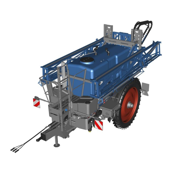
Layout and description LAYOUT AND DESCRIPTION Overview Chassis with drawbar Axle Drawbar with drawbar eye Chemical inductor Clean water tank Control centre and connection centre Main tank Front marking Lift mast with pendulum system Filter Energy chain Pump(s) Boom Stand Rear lighting equipment Wheel... -
Page 45: Basic Frame And Drawbar, General
Layout and description Basic frame and drawbar, general The basic frame is the basis for mounting further assembly groups. The towing hitch on the basic frame consists of: Drawbar Drawbar extension Connecting device with, e.g., drawbar eye or cross shaft Axles The axle of the implement is designed as a braked adjusting axle or as an adjustable... -
Page 46: Braking System
Layout and description Depending on the braking system, the maximum permissible speed of the imple- ment can be: 25 km/h 40 km/h Always pay attention to national regulations. The implement has an adjusting axle with adjustment increments of 50 mm for ad- justing various axle flange dimensions. -
Page 47: Compressed Air Brake
Layout and description 5.4.2 Compressed air brake Overview Compressed air tank Drain valve EU type-approved air brake system Double release valve – mano- euvring valve Double release valve – park valve Brake force regulator Combination brake cylinder (5) with: Guiding screw (6) ... - Page 48 Layout and description Function description Parking brake Only when the guiding screw (6) has been removed and placed and secured in the holder (7), is the parking brake ready for operation. Activate parking brake: Pull out red button of the park valve (3b). Release the parking brake: ...
-
Page 49: Hydraulic Braking System
Layout and description Disconnecting the brake lines After disconnecting the brake hose with the red coupling button, braking is initiated = automatic braking. Manoeuvring is then no longer possible. Brake cylinder If the operating pressure of the compres- sed air brake falls below 3.0 bar, the spring of the brake cylinder will lock the braking system. - Page 50 Layout and description Service brake The tractor's trailer control valve is used to operate the service brake hydraulically. When the tractor brake pedal is actuated, the hydraulic ram (2) extends. The hydrau- lic ram (2) pushes the brake lever (1) into the brake position.
- Page 51 Layout and description Parking brake The parking brake prevents the implement rolling away. Overview of hydraulic braking system By opening the brake valve (5), the preten- sioned compression spring (4) actuates the braking system via the hydraulic ram (2) and the brake lever (1). Parking brake, braked Activate the parking brake (7): ...
- Page 52 Layout and description Actuate the tractor brake pedal*. (The spring mechanism on the brake cylin- der is pretensioned and the parking brake is released) * The brake pedal on the tractor must be depressed forcefully for a short period. A quick tap is not enough. Rapid emergency brake For driving on roads: ...
-
Page 53: Liquid Flow
Layout and description Liquid flow 5.5.1 Overview 2500/3500 l 14 13 Clean water tank Canister rinsing nozzle Control valve Connection for cleaning gun Self-cleaning pressure filter Pressure control valve Flowmeter External cleaning Agitator Nozzle line Internal cleaning of main tank Part-width section valves Main tank Central bypass valve... -
Page 54: Description Of The Spraying Process Up To 3500 L
Layout and description Selection valve, spray pump Flush valve Switchover valve spraying agent / Drain valve pressure filter clean water Distributing valve Spraying pump Agitator control Suction valve Option electrical switching of spraying agent / clean water Option for internal cleaning of elec- 103 Electrical main switch option trical main container Electrical filling stop option... - Page 55 Layout and description During the spraying process, the spray pump (H) draws the spraying fluid from the main tank (7) via the switching valve (C), the selection valve (A) and the suction filter (9). The spraying fluid is then pumped to the nozzles via the diverting valve (D) and the pressure filter (3).
-
Page 56: Overview Of 4500 L
Layout and description 5.5.3 Overview of 4500 l 14 13 Clean water tank Canister rinsing nozzle Control valve Connection for cleaning gun Self-cleaning pressure filter Pressure control valve Flowmeter External cleaning Agitator Nozzle line Internal cleaning of main tank Part-width section valves Main tank Central bypass valve Drain valve... -
Page 57: Description Of The Spraying Pricess With 4500 L
Layout and description Selection valve, spray pump Flush valve Selection valve agitator pump Drain valve pressure filter Switchover valve spraying agent / Spraying pump clean water Distributing valve Agitator pump Agitator control Suction valve Option electrical switching of spraying agent / clean water Option for internal cleaning of elec- 103 Electrical main switch option trical main container... -
Page 58: Liquid Flow To Nozzles
Layout and description During the spraying process, the spray pump (H) draws the spraying fluid from the main tank (7) via the switching valve (C), the selection valve (A) and the suction filter (9). The spraying fluid is then pumped to the nozzles via the diverting valve (D) and the pressure filter (3). -
Page 59: Main Tank
Layout and description If the distribution is generally interrupted, all part-width section valves (20) are closed and the central bypass valve (21) is opened. By lowering the pressure in the piping system under the closing pressure of the membrane check valves, the valves close and the dripping stops. - Page 60 Layout and description The main tank is equipped with a tightly closed cover (1) Note: The tank opening is only intended for maintenance and repair work. The level of the main tank is indicated on the indirect level indicator (2). In addition, the level can be displayed by TankPilot via electronic level measure- ment.
-
Page 61: Clean Water Tank
Layout and description The drain valve (5) allows the contents of the main tank to be freely drained into a suitable collecting tank or sucked off with an external pump. Clean water tank The clean water tanks (1) are designed to hold clean water. -
Page 62: Hand-Wash Tank
Layout and description Hand-wash tank The hand-washing tank (1) is designed for receiving clean water. For example to facil- itate handwashing. Filter Functional and clean filters are a prerequi- site for trouble-free operation. The device comes complete with the follo- wing filters: ... -
Page 63: Pump(S)
Layout and description 5.10 Pump(s) The unit is equipped with one or two pumps (1) depending on the configuration. The pumps are designed for conveying spraying fluids. The pumps are driven mechanically via a PTO shaft. Depending on the equipment, the oil level indicator (6) of the pump is located below the ladder. -
Page 64: Basic Equipment
Layout and description 5.11.1 Basic equipment Selection valve spray pump Selection valve agitator pump Switching valve for spraying fluid/clean water Distributing valve Agitator control Suction valve Pressure filter Suction filter 27 Induction hopper fitting Display TANK control indica- tor (not shown) 5.11.2 Equipment from EES Pack 2 EES pack = Electronic accessori- es for water hydraulic actuation... -
Page 65: Selector Valves
Layout and description Selection valve spray pump Selection valve agitator pump Distributing valve Agitator control Suction valve Fill stop 101 Switching valve for spraying fluid/clean water Pressure filter Suction filter Induction hopper fitting Display TANK control indica- tor (not shown) 5.11.3 Selector valves Selection valve spray pump Pictogram... -
Page 66: Switchover Valve
Layout and description Selection valve agitator pump Pictogram Switch position Description Selector valve (B) is opened to the exter- nal connection. The spraying fluid in the main tank is not stirred. Selector valve (B) is switched to the main tank. -
Page 67: Distributing Valve
Layout and description 5.11.5 Distributing valve Pictogram Function Description Spraying The fluid is conveyed to the boom. The fluid is conveyed to the cleaning nozzles Internal cleaning in the main tank. The fluid is conveyed to the injector of the Washing-in chemical inductor and to the chemical induc- tor. - Page 68 Layout and description Container (1) The container can be swivelled in work- ing and transport positions. Induction fitting (2) including the following valves: Agitator nozzle (3) for dissol- ving and mixing spraying agents. Edge moistening (4) for: Spray spraying agent. ...
-
Page 69: Connections
Layout and description Shelf (10) The foldable shelf includes a built-in o- pening for placing the measuring cup. Suction valve (11) The suction valve allows the extraction from the induction bowl to be seamlessly adjusted. The suction valve is completely opened. -
Page 70: Pressure Limiting Valve
Layout and description 5.11.9 Pressure limiting valve The pressure limiting valve (1) is used to adjust the maximum system pressure of the implement. The pressure limiting valve is set at the factory and must not be adjusted. 5.11.10 Drain valve handwashing tank The handwashing tank can be emptied via the drain valve (1). -
Page 71: Automatic Filling Stop With Ees Pack 4
Layout and description See the separate operating instructions for the control unit. See the separate TANK control operating manual. 5.11.12 Automatic filling stop with EES pack 4 When equipped with TANK-Control, the filling quantity of the main tank can be pre- selected. -
Page 72: Storage Compartment
Layout and description 5.13 Storage compartment There is a storage compartment on the right-hand side of the machine in the direc- tion of travel. The storage compartment repels both wa- ter and dirt. 5.14 Recording the distance travelled The pulses of the distance travelled for automatic operation of the implement are picked up at the wheel of the implement. -
Page 73: Flowmeter
Layout and description 5.15 Flowmeter The flowmeter (1) measures the quantity of spray liquid flowing to the nozzles. In the operating terminal, e.g., the sprayed litres per minute (l/min) are displayed. 5.16 Pressure measuring device The pressure measuring device is provided for monitoring the spray pressure (Automa- tic mode) and for the indirect indication of filter contamination. -
Page 74: Hydraulic Control
Layout and description 5.18 Hydraulic control For the connection overview of the hydraulic hoses, see «, page 25». 5.18.1 Standard The implement’s hydraulic functions are carried out from the tractor via the control units. The hydraulic control system controls the following functions in the implement: ... -
Page 75: Load Sensing
Layout and description Raising/lowering Comfort FS 2: (1 single-acting control valve and Fold out/Fold in: pressure-free return flow required on Slope compensation the tractor's side) Reduction on both sides Comfort FS 1 load-sensing: Configuration of the functions with load- (Power Beyond connections requi- sensing red on the tractor's side) -
Page 76: Operation Terminal
All ISOBUS operation terminals can be used to operate the device. We recommend use of the LEMKEN CCI 1200, CCI-200 and LEM- KEN CCI-50 operation terminals with which other ISOBUS implements can also be operated. -
Page 77: Multifunction Handle
5.20 Multifunction handle The multifunctional handle makes it easier to operate the LEMKEN CCI terminal. A total of 24 functions can be operated with the control buttons (1) and the switch (a). The individual key fields (1) can be selec- ted with the switch (a). -
Page 78: Spraying
Layout and description 5.20.1 Spraying For this function, the switch (a) must be in the centre position. Function The programmed target quantity l/ha (100%) is sprayed On or Off Part-width sections of the boom are switched on from right to left Part-width sections of the boom are switched on from left to right Part-width sections of the boom... -
Page 79: Boom
Refer to the separate operating instructions of the respective operation terminal and the job computer. 5.21 Part-width section box CCI A 20 The LEMKEN CCI operation terminal can be extended with an additional safety edge for the electrical part-width section valves. This simplifies operation and enables nest- ing treatment. -
Page 80: Height Adjustment
Layout and description 5.22 Height adjustment The height of the sprayer boom is adjusted via a hydraulic cylinder (1) on the lift mast. Vertical oscillations on the sprayer boom are absorbed by a damper. 5.23 Pendulum suspension and slope compensation The sprayer boom is aligned horizontally with the pendulum suspension (1). -
Page 81: Stabiliser
Layout and description 5.24 Stabiliser The stabiliser (1) damps the swing sus- pension and therefore provides a better position of the boom on slopes. 5.25 DISTANCE-Control DISTANCE-Control automatically adjusts the boom to the existing terrain. A sensor (1) on the left and right side of the boom detects the distance between the boom and the target surface. -
Page 82: Hydraulic Flow Dividers And Pressure Limiting Valves
Layout and description A pendulum sensor on the boom (3) rec- ords the slope angle of the boom. Additional dampers (4) minimise the vibra- tions on the boom. See the DISTANCE-Control operating in- structions. 5.26 Hydraulic flow dividers and pressure limiting valves A hydraulic flow divider (1) is provided for each of the functions symmetrical folding of the boom and separate folding of the... -
Page 83: Boom
Layout and description 5.27 Boom 1 Boom 2 Height adjustment 3 Centre piece 4 Arm 1 5 Arm 2 6 Arm 3 7 Guard plate 8 Nozzle holders Nozzle holders (8) are fitted to the boom (1) to hold the nozzles. Two nozzle hol- ders (8) are planned per m of working width of the boom. -
Page 84: Single Nozzle Valves
Layout and description 5.27.2 Single nozzle valves The nozzles on the outer arms on the left and the right are controlled by individual nozzle valves and are combined as a sec- tion. The user can switch the respective section on and off. 5.27.3 Nozzle holders The implement can be equipped with the following nozzle holders:... -
Page 85: Nozzles
Layout and description 5.27.4 Nozzles The user can attach different nozzles to the nozzle holders. Each nozzle type has different volumetric flows, spray patterns, drop sizes and nozzle characteristics. The following aspects must be observed when selecting nozzles: Spraying agent used ... -
Page 86: Drop Hose
Layout and description 5.28 Drop hose The drop hoses (1) are intended for the application of liquid fertilizer. Burning of foliage is hardly possible, due to the direct application onto the ground. -
Page 87: Preparations
Preparations PREPARATIONS Preparations on tractor 6.1.1 Checking the suitability of the tractor for the implement Check the following before attaching the implement to the tractor: Check the required voltage sources Check the voltage sources of the tractor. A voltage source is available on the tractor for each device drawing power. - Page 88 Preparations Checking required hydraulic equipment To check the tractor's hydraulic equipment: A separate hydraulic connection is available for the hydraulic braking sys- tem. There is a hydraulic connection available for each consumer. There is a suitable control unit availab- le for each consumer.
- Page 89 Preparations Consumer EW DW DR Sprayer boom height ad- Blue justment Boom flaps Green P2/T2 P11/T1 Manual tiller steering system White Yel- Hydraulic pump drive P7/T7 low/white Yel- Electro-hydraulic operation P6/T6 low/white Electro-hydraulic operation EW = single-acting control unit DW = double-acting control unit DR = pressure-free return flow LS = load-sensing signal cable Requirements on tractor connection points...
- Page 90 Preparations Risk of damage to the cardan shaft or the implement CAUTION If the trailer coupling connection is not within the permissible di- mensions, the cardan shaft or the tractor-implement combination may be damaged when cornering. Ensure a trailer coupling connection to the tractor with the permis- sible distances, thereby guaranteeing a clearance of at least 100 mm around the cardan shaft.
-
Page 91: Check Tractor Tire Pressure
Preparations 6.1.2 Check tractor tire pressure The air pressure in the tractor tyres must be identical, in particular, on the rear wheels. Check the air pressure in the tractor's tyres. If necessary, adjust the air pressure in the tractor's tyres. 6.1.3 Installation of the operation terminal ... -
Page 92: Air Brake System
Preparations 6.2.1 Air brake system For the air brake system of the implement the tractor must be equipped with a two-hose air brake system with coupling heads according to ISO 1728. 6.2.2 Hydraulic brake system For the hydraulic brake system, the tractor must be fitted with a hydraulic coupling as per ISO 5676. -
Page 93: Preparations On The Implement
Preparations Preparations on the implement 6.3.1 Standard procedure To prepare the implement in general: Attach implement. Check whether the implement is horizon- tal in the direction of travel. If the implement is NOT horizontal in the direction of travel: Have the drawbar adjusted by service personnel or, if necessary, adjust the height of the attachment point on the... -
Page 94: Implement With Compressed Air Brake
Preparations 6.3.2 Implement with compressed air brake Risk of accident due to deactivated brakes DANGER To enable unloading and manoeuvring without a compressed air supply, the brake cylinders and thus the parking brake were deac- tivated ex works by means of guiding screws. Make sure the guiding screws have been removed prior to initial commissioning. - Page 95 Preparations Insert the guiding screw (1) into the hol- der (5) on the brake cylinder (3). Secure the guiding screw (1) using a peg and nut. Adjusting the brake force regulator The brake force regulator has seven ad- justment positions.
- Page 96 Preparations Primus 2500/3500 Actual axle load [kg] Adjustment Static radius of the tyres [757 mm - 819 mm]* From 1 (locked) 2700 3200 3201 4100 4101 5300 5301 6100 6 (locked) 7 (locked) * Rolling circumference of the tyres, see chapter “Tyres” on page 231 Primus 4500 Actual axle load [kg] Adjustment...
-
Page 97: Attaching The Implement
Preparations Attaching the implement Aim: Device is fully available for distribu- tion. Application: Before use ATTENTION: To protect the tractor and device, the latter is suspended in a hori- zontal position at a vertical angle of +/-5° to the tractor. 6.4.1 Attaching the implement with drawbar eye ... - Page 98 Preparations coupling. If the trailer coupling on the tractor can- not be adjusted to allow horizontal sus- pension of the device, the device can be converted. See « Conversion of device, page 99». Slowly and carefully, pull the tractor's trailer coupling up to the towing eye of the implement.
-
Page 99: Attaching The Implement With Cross Shaft
Preparations 6.4.2 Attaching the implement with cross shaft Switch the tractor's hydraulic system to position control mode. Back the tractor straight up to the im- plement. ATTENTION: Do not slide the device in the process. If the device is on the sup- port legs, moving the device may dama- ge them. - Page 100 Preparations Switch the hydraulic system to depres- surised. Connect hydraulic hoses (3) to tractor. o Make certain they are assigned correctly. o Note the hydraulic system la- bels. Connect the electrical lines to the tractor. Test the lighting equipment. ...
-
Page 101: Conversion Of Device
Allow the height of the towing eye im- plement to be adjusted by re-screwing. Have other traction loops approved by LEMKEN installed, see «Traction loops, page 226». In line with national provisions: Have the towing device and/or drawbar components replaced in the registration papers. -
Page 102: Implement With Hydraulic Braking System
Preparations 6.4.5 Implement with hydraulic braking system Release parking brake (3): Close the brake valve (1). Actuate the tractor brake pedal. (The spring mechanism on the brake cylinder is pretensioned and the parking brake is released) Attach break away cable (2) to the trac- tor. - Page 103 Preparations Mount one of the following PTO shaft ends to the tractor: Cardan shaft end is marked with the tractor symbol Wide-angle joint Mount opposite PTO shaft end to the device. Shortening a non-telescopic PTO shaft. ...
-
Page 104: Determining Filling Quantities Of The Implement
Preparations Hold the cut-off piece of the inner protec- tion tube (2) over the inner profile tube (9) and cut off the inner profile tube (9) at a right angle. Deburr and clean the outer and inner profile tubes. ... -
Page 105: Installing The Intended Nozzles
Preparations Installing the intended nozzles The mesh size of the pressure filters and the nozzle filters must always be the same or smaller than the flow cross-section of the nozzles used. The pesticide manufacturer’s instructions regarding the appropri- ate mesh size must be observed. Before spraying, the intended nozzles must be selected and installed. - Page 106 Preparations The multiple nozzle holders may only be rotated when the nozzles are switched off. Adjust the multiple nozzle holders to the intended nozzles. Unless you need all nozzles of a section: For single nozzle holders, close indivi- dual nozzles with blind caps (1).
-
Page 107: Volumetric Metering Of The Nozzles And Calibrating The Flowmeter
Preparations The arrow in the following two graphics indicates the direction of travel of the implement. A = nozzle distance 0.5 m H = spraying height 1.0 m Volumetric metering of the nozzles and calibrating the flowmeter Automatic control of the distribution rate [l/ha] is achieved via the travel speed and the flow of the spraying fluid through the nozzles. -
Page 108: Volumetrically Meter The Nozzles
Preparations To ensure the calculated flow rate corre- sponds to the actual flow rate, the flow rate can be checked by volumetric metering the nozzles and the flowmeter can be calibrat- Applications: Before commissioning for the first time At the start of each season ... - Page 109 Preparations Preparations for the tractor-unit combination Fill the main tank with at least 500 l of clean water. Place the tractor-device combination on a surface with the following properties: Device can be placed horizontally. Sprayer boom can be folded out. ...
- Page 110 Preparations Volumetric metering Go to a nozzle and collect the water for exactly 60 seconds with the prepared measuring cup. Write down the amount of water applied. Repeat the last two steps on at least 3 nozzles with different part-width sec- tions.
-
Page 111: Calibrate The Flowmeter
Preparations If the output quantities of the measured nozzles differ: Replace nozzles. Repeat the volumetric metering process. Alternatively: Have nozzles checked by a specialist on a test bench. 6.7.2 Calibrate the flowmeter The control of the device requires the pulse values of the flowmeter to calculate the automatic metering. -
Page 112: Calibrate The Speed Sensor
Preparations 6.8.2 Calibrate the speed sensor. The speed sensor is calibrated with the controller of the device. The operating instructions in the "SPRAY- ER-Controller MIDI" manual describe how to calibrate the speed sensor in chapter "7.6 Selecting and configuring the speed sensor". - Page 113 Preparations To check the compatibility of pesticides with the device materials: Mix pesticides according to manufac- turer's instructions. While stirring, follow the manufacturer’s instructions for the pesticide. Immerse vulnerable parts of the device (e.g. hoses) in the pesticide for several hours.
-
Page 114: Operation
Operation OPERATION Prepare device for use 7.1.1 Adapt device for use Target: The external conditions and equipment of the device are appropriate for the intended use. Check the following before distribution and adjust if necessary: Check whether the unit contains anti- freeze. -
Page 115: Prepare The Device For Operation In Frosty Conditions
Operation 7.1.2 Prepare the device for operation in frosty conditions Risk of accident due to frozen braking system of the device WARNING If the braking system of the device is frozen, it is no longer possi- ble to brake the device. This may even be fatal or result in serious injuries. -
Page 116: Drain Antifreeze Agent
Operation Fill the following containers with liquids: Fill the handwash container with water, see "Filling water canister for hand washing, page 115". For cleaning purposes on the field Fill the clear water tank with water, see "Filling the clean water tank, page 116". ... -
Page 117: Filling And Emptying The Water Canister For Hand Washing
Operation Filling and emptying the water canister for hand washing The water canister for hand washing is in- tended exclusively for cleaning purposes and is not suitable for housing cleaning agents and sprays. CAUTION: Germs or traces of cleaning agents and sprays may contaminate the water canister for hand washing. -
Page 118: Filling And Emptying The Clean Water Tank
Operation Filling and emptying the clean water tank The implement is equipped with two inter- connected clean water tanks. The clean water is used to clean parts of the implement and must meet the following requirements: Free from germs or organisms ... -
Page 119: Emptying The Clean Water Tank
Operation 7.3.2 Emptying the clean water tank To ensure no vacuum when emptying the clear-water tank: Before emptying check whether the ven- tilation valves (2) are functional. Unscrew and remove the union nut (4) of the connecting hose. The water runs out of the clear water tanks. -
Page 120: Standard Procedure
Operation 7.4.1 Standard procedure Precondition: The drain valve (1) is closed and secured with the blind cap (2). Read the usage instructions for the spraying agent. Observe the respective national regula- tions and standards regarding the hand- ling of spraying agents: e.g. water pro- tection zones, filling of equipment etc. -
Page 121: External Filling Connection
Operation 7.4.2 External filling connection Application: Pump water or ready-mixed spraying fluid with an external pump into the main tank. Remove the blind cap (1) of the filling connection. Attach the filling hose (2) to the filling port. ... -
Page 122: Intake Connection
Operation After filling the main container: Set the filling valve (3) to close. Remove filling hose. Seal the filling connection with the blind cap (1). spraying fluid can also be pumped into the main tank via the filling connection with an external pump. - Page 123 Operation Approach* Switch on the operation terminal. Switch on the PTO shaft. The pump is switched on and driven via the PTO shaft. Operate pump at a maximum of 550 rpm. Remove the blind cap of the intake connection (1).
- Page 124 Operation Monitor the filling of the main tank with the following aids: Fill level indicator (4) Display unit at the operating and ad- justment centre Operation terminal To ensure the main container does not overflow: Stop filling the main tank in ti- ...
- Page 125 Operation Continued procedure with fill stop* Switch diverting valve to spraying mode. Enter the required filling quantity in the control, see operating instructions SPRAYER-Controller MIDI, chapter 6.1.3. Start filling process: Press the softkey in the control. ...
-
Page 126: Chemical Inductor
Operation Pull filling hose out of the external water source. remove the filling hose from the external water connection. Remove the filling hose from the intake connection. Close the intake connection with the blind cap. 7.4.4 Chemical inductor Application: Rinse unmixed or ready- mixed spraying fluid into the main tank. - Page 127 Operation For the storage of small spray agent con- tainers or a measuring cup, the tray can be folded upwards. For storing small spray agent containers or a measuring cup: Swivel the shelf (2) upwards. Swivel the holder (3) underneath the shelf (2).
- Page 128 Operation Switch on pump via PTO shaft. Operate the pump at the rated speed. Switch the diverting valve to the induc- tion lock. If necessary, regulate the performance of the agitator regulation. Open the valve for edge moistening and fill approx.
- Page 129 Operation After rinsing the spray agent: Clean the empty spray agent canister. See « Cleaning empty canisters, page 130». Rinse the chemical inductor with clean water. See «Rinsing the chemical induc- tor, page 135». If canisters are not cleaned or the pipe sys- tem is flushed: ...
-
Page 130: Adjust Flush Valve
Operation Adjust flush valve Targets: Pressure filter does not clog. Flushing valve adjustment (1) matches distribution rate[l/ha]. Application: Configure automatic distribu- tion. Additional information: Dirt particles col- lected by the pressure filter are returned to the main tank via the rinsing valve and the agitator. - Page 131 Operation Switch the selection valve of the spray pump (A) to change-over valve (C). Place the switchover valve (C) on the clean water tank. In the control: Manual mode for control- ling the distribution rate. The work mask view changes. ...
-
Page 132: Cleaning Empty Canisters
Operation Cleaning empty canisters Spray agent can endanger health and pollute the environ- ment CAUTION If you do not close the rocker arm for the cleaning nozzle, you may be sprayed by the cleaning nozzle. You and the environment may be polluted with residual particles of spray agents. ... - Page 133 Operation After cleaning the spray agent canister: Close the rocker arm of the cleaning nozzle. If necessary, clean further empty spray agent canisters. If necessary, rinse the chemical inductor. Drain the chemical inductor empty. Close the suction valve. ...
-
Page 134: Cleaning Gun At The Chemical Inductor
Operation If it is not possible to return empty and cleaned canisters: Recycle the empty and cleaned spray agent canisters. Cleaning gun at the chemical inductor Observe the applicable standards and regulations for cleaning the implement. The cleaning gun may only be operated with clean water. ... - Page 135 Operation Remove the cleaning gun (1) from the holder (2). Switch the diverting valve to chemical inductor. Switch the rocker arm for the cleaning gun upwards to ON.
- Page 136 Operation The cleaning effect of the cleaning gun can be infinitely varied with the rocker arm (1). Press the handle (2) to activate the cleaning gun (3). After releasing the handle (2), the spraying process is interrupted immediately. For permanent operation of the cleaning gun: ...
-
Page 137: Rinsing The Chemical Inductor
Operation Rinsing the chemical inductor After cleaning empty spray agent canisters, the chemical inductor can be rinsed with clean water. Spray agent can endanger health and pollute the environ- CAUTION ment When the cover is open, residual particles of spray agent can es- cape and endanger the operator and the environment. - Page 138 Operation Open the suction valve so that no liquid can escape from the chemical inductor tank. After rinsing the chemical inductor, switch the following rocker arms down- wards to OFF to close the valves: Cleaning nozzle or canister rinsing nozz- ...
-
Page 139: Folding Out Sprayer Boom
Operation Folding out sprayer boom Applications: For volumetric metering or calibrating Before distribution To clean the piping system Potentially fatal electric shock due to overhead lines DANGER The unit can reach the height of overhead lines when folded out. This could cause an electrical accident that leads to a potentially fatal electric shock or fire. -
Page 140: Device With Standard Equipment
Operation Raise the sprayer boom with the tractor control units to the stops (1). ATTENTION: The sprayer boom swings when the device moves.When the spra- yer boom reaches the topmost position on the lift mast, the sprayer boom is rea- ligned. - Page 141 Operation Raise the implement before folding it up Background: When the machine moves, the sprayer boom swings. To allow the sprayer boom to be placed in the storage pockets, the sprayer boom is raised up to the stop of the lifting boom be- fore folding.
- Page 142 Operation How to start the sprayer boom with the control unit in general is described in chap- ter 6.2.4 of the operating manual SPRA- YER controller MIDI 3.0. Extending the implement For information on how to fold out the sprayer boom with the control unit, refer to the operating instructions for the SPRA- YER controller MIDI 3.0 in Chap.
-
Page 143: Adjusting The Spring Stabiliser
Operation 7.10 Adjusting the spring stabiliser The spring stabiliser can be adjusted to suit the terrain. In the basic setting of the spring stabiliser, 15 chain links (1) are attached. Right hand stabilising chain Left hand stabilising chain Terrain Damping Stabilising chain Steep slope with firm Stronger... -
Page 144: Trial Operation Of Device
Operation 7.11 Trial operation of device Applications: Initial commissioning Getting to know the individual control functions Before initial use with spraying agents After maintenance operations After repairs Put the ladder in the transport position: ... -
Page 145: Working With The Device
Operation Switch agitator control to maximum agi- tator action. Perform trial spraying operation: Switch on the nozzles. Work with the device, see "Working with the device, page 143". Check all components for function and tightness. ... - Page 146 Operation Adjust pendulum system. Adjust stabiliser. Set selection valve to main tank. Set diverting valve to spray mode. Adjust the agitator control to the agitator intensity according to the usage instruc- tions of the spraying agent used. ...
-
Page 147: Apply Spraying Agent
Operation 7.12.2 Apply spraying agent Bring the tractor-implement combination into position. Spraying: Move over the processing area with the tractor-device combination. Switch on the nozzles. During application, drive at a speed that matches the installed nozzles and the application rate set. - Page 148 Operation At the end of the spray lane, switch off the nozzles and turn them around. Continue distribution in the next row. If the edge of the cultivated area runs diagonal to the cultivated area, turn off outer nozzles or sections.
-
Page 149: Working On Rugged Terrain Or On A Slope
Operation 7.13 Working on rugged terrain or on a slope By changing the centre of gravity to com- pensate for a slope, the position of the boom can be adjusted to adapt to rugged terrain or a slope so it is parallel to the ground. -
Page 150: Switch Edge Nozzles
Operation The following edge nozzles are available: Edge nozzles with one-sided spray cone for sharp-edged treatment Extension nozzles - variable and ad- justable jet nozzles 7.15.1 Switch edge nozzles The edge nozzles are switched via the control unit: See Chapter 7.9.2 of operating instructions for SPRAYER controller MIDI 3.0. -
Page 151: Working With Drop Hoses
Operation Install edge nozzles on the outermost nozzle holders. Test spray with water to see whether the desired spray pattern is achieved. If the desired spray pattern is not achie- ved: Reposition the edge nozzles. Use other edge nozzles. ... - Page 152 Operation Place the metering washer (2) with the label facing upwards in the bayonet cap (3). Place the seal (1) on the metering washer in the bayonet cap (3). Assemble the drop hoses (6) on the nozzle holders (7) along with the instal- led seals and metering washers.
-
Page 153: Spraying With Drop Hoses
Operation Carefully fold in the boom. The drop hoses may not get caught on any components or stuck in the wheels. When folding in the boom, pay attenti- on to the incline position of the imple- ment and the acceleration forces when cornering. -
Page 154: Standard Procedure
Operation Potentially fatal electric shock from overhead lines DANGER The unit can reach the height of overhead lines when folded out. An electrical flashover between the lines and the implement can occur, leading to a potentially fatal electric shock or fire. ... -
Page 155: Devices With Standard Equipment
Operation 7.17.2 Devices with standard equipment Implements with standard equipment are raised, folded up and lowered using the control unit of the tractor. 7.17.3 Devices with Comfort FS equipment Devices with Comfort FS equipment are started, folded and shut down with the con- trol unit of the device. - Page 156 Operation The “folding“ mask opens. Press the softkey. Press and hold the softkey until the sprayer boom has reached the stop on the lift mast boom. Release softkey. The sprayer boom is realigned. After the sprayer boom has reached the topmost position on the lift mast and is aligned, the sprayer boom can be folded.
-
Page 157: System Cleaning With Partially Filled Main Container
Operation Equipment-specific differences when folding in: Comfort FS 1: Spray boom is completely folded in. From Comfort FS 2 unit: Spray booms can be folded in part width sections. The outer outriggers can be folded in symmetrically or left in a reduced positi- on. -
Page 158: Flush The Pipe System Before Interruption
Operation System cleaning conditions for partially filled main tank: The concentration of the spray agent remains unchanged. No clean water flows into the main tank. No spraying agent flows into the clean water tank. 7.18.1 Flush the pipe system before interruption Description* * Position designations correspond to the position designations of the fluid lines. - Page 159 Operation The spray pump (H) draws the water from the clean water tank via the switching val- ve (C), the selection valve (A) and the suc- tion filter (9). The water is then pumped to the nozzles via the diverting valve (D) and the pressure filter (3).
- Page 160 Operation Switch on the pump (H) via the PTO shaft. Operate pump at the minimum speed (330 rpm). Apply approx. 50% of the content of the clean water tank to an unsprayed area. During the distribution: Move with increased travel speed. ...
-
Page 161: Stir Spraying Fluid Before Distribution
Operation To open the control valve (2):Press and hold softkey for 4 seconds. 7.18.2 Stir spraying fluid before distribution Target: To keep the piping system and nozzles functioning and prevent blockage due to decomposed spray solution. Application: Distribution continued after an interruption. - Page 162 Operation The spray pump (H) draws the spraying fluid from the main tank (7) via the swit- ching valve (C), the selection valve (A) and the suction filter (9). The spraying fluid is pumped to the closed part-width sections via the diverting valve (D). The spraying fluid continues to flow through the central bypass valve (21) into the agitator (5).
- Page 163 Operation Switch the agitator regulation (E) to ma- ximum agitator action. Observe the instructions for use of the spraying agent used. Switch on the pump (2500/3500 l = H | 4500 l = I) via the pump nozzle. ...
-
Page 164: Cleaning
Cleaning CLEANING Standard procedure Remaining quantities of spraying agent must not be drained off at ATTENTION the edges of the road or discharged into the sewer system. Where possible: Reuse collected spraying agent (after consul- ting the respective spraying agent manufacturer). ... -
Page 165: Emptying The Main Tank
Cleaning The following should be noted during the cleaning: Regulations of the spraying agent manu- facturer Regulations of the nozzle manufacturer These operating instructions Other regulations for handling spraying agents Standard procedure: Emptying main container, see "Emptying the main tank, page 163". -
Page 166: Pump The Remaining Quantity From The Main Container
Cleaning the spraying agent must be pumped into an external tank, the residual content in the main tank must be drained off. Main tank pumping and draining is also required when spraying agent remains in the main tank during spraying intervals, and it is unable to be agitated because of deposits, bonding etc. -
Page 167: Draining Spray Agent From The Main Tank
Cleaning After pumping out: Switch off pump via PTO shaft. Remove hose. Close pump connection with sealing cap. After the remaining quantity has been pumped out, internal cleaning is necessa- ry, see "Internal cleaning, page 166". 8.2.3 Draining spray agent from the main tank ... -
Page 168: Internal Cleaning
Cleaning Close the drain valve (2). Install the locking cap (3). Ensure the connection is leak-tight. Carry out internal cleaning and, if neces- sary, external cleaning and filter cleaning. Internal cleaning ATTENTION Deposits from the spray solution contaminate the main tank, the piping system and the nozzles. -
Page 169: Standard Procedure
Cleaning Additional information: Depending on the pesticide and subsequent intended use, the main container, piping system and nozzles may have to be cleaned with cleaning agents.Please refer in this case to the operating instructions for the pesticide products and cleaning agents used. 8.3.1 Standard procedure Preconditions: ... - Page 170 Cleaning In the control select the manual mode for controlling the spraying fluid quan- tity. Switch on the nozzles. Reduce spray pressure. Move with increased travel speed. Open and close part-width section va- lves (20) via the control unit. ...
-
Page 171: Clean Main Container
Cleaning 8.3.2 Clean main container Description* The spray pump (H) draws the clean water from the clean water tanks via the switch valve (C), selection valve (A) and suction filter (9). The clean water is then pumped into the main tank (7) via the diverting valve (D) and the internal cleaning nozzles (6). - Page 172 Cleaning After the main tank (7) has been filled with water, the switchover valve (C) is switched to the main tank. The spray pump (H) draws the spraying fluid from the main tank (7) via the swit- ching valve (C), the selection valve (A) and the suction filter (9).
- Page 173 Cleaning Manual procedures Preconditions: Adjustments, see "Internal cleaning, pa- ge 166" Nozzles are switched off. At the control centre, the selection valve (A) is switched to a change-over valve (C). For a device with 4500 l:Selection valve (B) is switched to main tank.
- Page 174 Cleaning Procedure as for EES package 2 Preconditions: Adjustments, see "Internal cleaning, pa- ge 166" Nozzles are switched off. Operation terminal is switched on. Functions are activated At the control centre, the selection valve (A) is switched to a change-over valve (C).
- Page 175 Cleaning Press the blue button at the control centre.LED lights up. If necessary, add cleaning agent to the main container. When the main tank contains approx. 80 - 90 l:Stop internal cleaning: Switch the switchover valve (101) to main container in the control system.
-
Page 176: External Cleaning
Cleaning External cleaning CAUTION When cleaning, there is a risk of contact with pesticide. Wear personal protective equipment during the cleaning. Aim: Clean equipment, unintentional drip- ping or discharge of adhesive spray agent is prevented. Applications: If the device is contaminated with spraying agent. -
Page 177: Prepare External Cleaning
Cleaning ATTENTION: During external cleaning, diluted spraying agent will flow onto the substrate. Clean the outside on an unsealed surface. Recommendation: Most recently treated spraying surface 8.4.1 Prepare external cleaning Park the tractor-unit combination on an unsealed area. ... -
Page 178: Perform External Cleaning
Cleaning 8.4.2 Perform external cleaning Switch on pump via PTO shaft. Operate pump at the minimum speed (350 rpm). Remove spray gun from holder. Pull the required hose length out of the hose reel. Spray device with the spray gun. ... -
Page 179: Cleaning The Filter
Cleaning Cleaning the filter CAUTION When cleaning the filter, there is a risk of contact with pesti- cide. Wear personal protective equipment during the cleaning. 8.5.1 Standard procedure To remove particles of dirt from the sys- tem: Close flushing valve before the final day of spraying. -
Page 180: Press Filter
Cleaning Remove the seal (1). Loosen (3) union nut. Remove the suction filter (2). Clean the individual components of the suction filter with water and a soft brush. Install (2) suction filter. When mounting, ensure the seal (4) is correctly inserted and not crushed. - Page 181 Cleaning Remaining spray agent is drained from the pressure filter (1) and system through the rinsing valve. Flushing valve (F) closed to the limit po- sition by turning it to the right. Procedure Loosen the union nut (2) of the pressure filter.
-
Page 182: Detaching The Implement
Detaching the implement DETACHING THE IMPLEMENT Only detach the implement when the main tank and the clean wa- ter tank are empty. Preparations Aim: The implement is safely stored un- derneath until the next use. Applications: After one use ... -
Page 183: After One Use
Detaching the implement 9.1.1 After one use Move the implement to a location that meets the following requirements: Load-bearing and flat standing surface Ventilated Dark Roofed ATTENTION: Light (UV radiation) and weather conditions accelerate the aging process of the equipment materials. -
Page 184: Put Implement Into Park Mode
Detaching the implement Select a frost-proof and darkened place with roof for storage. Carry out all further preparations as after an operation. If there is no freeze-free storage space available: Provide biodegradable antifreeze. ATTENTION: Do not use liquid fertiliser. Liquid fertiliser will damage the rubber components. -
Page 185: Fitting Stand
Detaching the implement Implement with hydraulic braking system: Manually pull the break away cable (2). Open the brake valve (3). Release break away cable from the trac- tor. Use the wheel chocks to secure the wheels of the implement against rolling away. -
Page 186: Detaching The Implement
Detaching the implement Detaching the implement Uncouple the brake lines from the trac- tor. Attach the brake line to the holder on the implement side. Uncouple the cardan shaft from the trac- tor. Attach the cardan shaft to the holder on the device side. -
Page 187: Maintenance And Repairs
Maintenance and repairs MAINTENANCE AND REPAIRS 10.1 Special safety instructions 10.1.1 General Risk of injury when carrying out maintenance and repair work There is always the risk of injury when carrying out maintenance and repair work. WARNING Use suitable tools, suitable climbing aids, platforms and support elements. -
Page 188: Immobilise The Implement For Maintenance And Repairs
Maintenance and repairs 10.1.4 Immobilise the implement for maintenance and repairs Risk of accidents when tractor starts up Injuries may occur if the tractor starts moving during maintenance and repair work. Switch off the tractor engine before carrying out any work on the WARNING implement. -
Page 189: Utilised Tool
Maintenance and repairs 10.1.7 Utilised tool Risk of accident due to use of unsuitable tool WARNING If working with an unsuitable or defective tool, there is a risk of ac- cidents and injuries. Perform all work on the device with a suitable and functional tool only. -
Page 190: Safely Maintain The Device
Maintenance and repairs 10.2 Safely maintain the device Personnel Some activities, e.g. work on braking sys- tems, require service personnel (e.g. in ag- ricultural machinery workshops). These activities are marked in the maintenance schedule. Preparations Switch off the implement. ... -
Page 191: Environmental Protection
Maintenance and repairs For dismantling and mounting heavy com- ponents: Use hoisting gear. To avoid slipping of tools: Use aids to reduce the amount of force required, e.g. extensions. Check nuts and screw heads etc. for wear and tear. Consult a specialist if ne- cessary. - Page 192 Maintenance and repairs Interval Activity Joints Traction loop Parking support Ropes Axle slack adjuster Axle camshafts Ladder Lift mast Self-aligning bearing Carriage guide Pendulum guidance Rope pulley Boom Bolted connections Hydraulic hoses Air filter, compressed air brake Chemical inductor Pump Pressure accumulator, pump Axle Braking system...
-
Page 193: Oils And Lubricants
Maintenance and repairs 10.5 Oils and lubricants Amount per mainte- Assembly group Oil / lubricant nance interval Axle High-temperature Depending on the lubrica- grease, tion points e.g. EcoLi91 Grease nipple and open Multi-purpose grease Depending on the lubrica- lubrication points tion points Sliding areas on the lift mast OKS Mox-Active 451... -
Page 194: Additional Care Once The Season Is Over
Maintenance and repairs 10.6.1 Additional care once the season is over Grease all pins. Grease all piston rods in the hydraulic ram. Grease all surfaces that are at risk of rusting. 10.6.2 Traction loop Lubrication interval: Every 8 operating hours ... -
Page 195: Stand
Maintenance and repairs 10.6.3 Stand Lubrication interval: Every 8 operating hours Lubricate grease nipple (1). 10.6.4 Slack adjuster Lubrication interval: Every 8 operating hours Lubricate grease nipple (1). -
Page 196: Camshaft
Maintenance and repairs 10.6.5 Camshaft Lubrication interval: Every 8 operating hours Lubricate grease nipple (1). 10.6.6 Lift mast and self-aligning bearings Lubrication interval: Every 8 operating hours Lubricate both sliding surfaces on the lift mast (1) using a brush. -
Page 197: Skids And Pivoted Guide
Maintenance and repairs Lubricate the four sliding surfaces of the lift mast (2). To lubricate these sliding surfaces, use chain and adhesive lubricant OKS Mox- Active 451. 10.6.7 Skids and pivoted guide Lubrication interval: Every 8 operating hours ... -
Page 198: Rope Pulley
Maintenance and repairs 10.6.8 Rope pulley Lubrication interval: Every 8 operating hours Lubricate the grease nipple on the pulley (1). 10.6.9 Rope Lubrication interval: Every 50 operating hours After cleaning, lubricate the ropes with lubricant for wire ropes. -
Page 199: Boom
Maintenance and repairs 10.6.10 Boom Lubrication interval: Every 8 operating hours The following lubrication points are located on the left and the right-hand side of the boom. Images with the lubrication points are only shown from one side of the boom. The number of lubrication points shown refers to the total number of points on both the left and the right-hand side of the... - Page 200 Maintenance and repairs Pivot joint 1 Lubricate 4 grease nipples on pivot joint 1 (1). Pivot joint 2 Lubricate 4 grease nipples on pivot joint 2 (1). Lubricate 2 grease nipples on strut (2).
- Page 201 Maintenance and repairs Lubricate 4 grease nipples on the folding lever (3). Folding cylinder Boom with 2 folding cylinders: Lubricate each of the 2 grease nipples on the piston bottom (1) and on the pis- ton rod (2) of the folding cylinder (1) every 8 operating hours.
- Page 202 Maintenance and repairs Pivot joint 3 Lubricate 4 grease nipples on folding le- ver 3 (1). Lubricate 4 grease nipples on the folding lever 2 (2).
-
Page 203: Chemical Inductor
Maintenance and repairs 10.6.11 Chemical inductor Lubrication interval: Every 8 operating hours Lubricate the 4 grease nipples on the holder (1). 10.7 Drive shaft Use lithium-lubricated grease, consistency class NL-G12. The drive shaft must be serviced on the tractor side and the implement side. Protective tube Safety chain Sliding tube not illustrated (inside the... -
Page 204: Safety Chain
Check the manufacturing date of the hydraulic hoses. Replace after 6 years at the latest. Only use hydraulic hoses approved by LEMKEN. 10.9 Oil filter in electrohydraulic operation Dirty oil results in increased wear and damage to the implement’s hydraulic system. -
Page 205: Check Oil Filter
Maintenance and repairs nation display (2) becomes visible. If the filter element in the oil filter is not immediately replaced, un- filtered oil is routed into the electrohydraulic system. 10.9.1 Check oil filter Check interval: Every 8 operating hours The oil filter is equipped with a visual con- tamination display with memory function. -
Page 206: Braking System
Maintenance and repairs Open the door (3). Place suitable drip pan under the oil fil- ter. Open the filter cup in the oil filter. Remove filter cartridge. Insert new filter cartridge. Reinstall filter cup. ... - Page 207 Maintenance and repairs Press down screw-in plug using Allen key. Turn screw-in plug by 90°. o In the open position the spring presses the screw-in plug up- wards. Remove screw-in plug (1), spring (2), filter screen (3) and disc (4). ...
-
Page 208: Tightening Torques
Maintenance and repairs Insert screw-in plug, spring, filter screen and disc into housing of the coupling head. Press down screw-in plug using Allen key. Turn screw-in plug by 90°. o In the closed position the spring presses the screw-in plug upwards. -
Page 209: Bolts And Nuts Made Of Steel
Maintenance and repairs The tightening torques set out below refer to screw connections that are not specifically mentioned in these operating instructions. Specific tightening torques to be applied are mentioned in the text. Identify the relevant screw connection by means of the spare- parts list or the markings on the screw head. -
Page 210: Wheel Nuts
Maintenance and repairs Diameter [Nm] M 12 M 14 M 16 M 18 M 20 M 22 M 24 M 27 10.11.4 Wheel nuts The tightening torque for the wheel nuts (1) with centring locking bar (2) is 510 Nm. ... -
Page 211: Check The Connections To The Tractor
Maintenance and repairs 10.12 Check the connections to the tractor 10.12.1 Hydraulic connections Risk of accidents due to escaping hydraulic fluid Hydraulic fluid which is ejected under high pressure (hydraulic oil) WARNING can penetrate the skin and cause serious injuries. In the event of injuries, consult a doctor immediately. -
Page 212: Pump
Maintenance and repairs 10.13 Pump 10.13.1 General information Requirement for pump operation: Sufficient oil Correct pressure at the pressure ac- cumulator Proper membranes Properly functioning valves Annual maintenance performed by a quali- fied and well-trained person: ... -
Page 213: Check Oil Level
Maintenance and repairs 10.13.2 Check oil level The oil level of the pump is checked at the sight glass during operation. WARNING: A universal shaft drives the pump. Persons may be entangled, pulled in and seriously injured by the cardan shaft. -
Page 214: Refill Oil
Maintenance and repairs 10.13.3 Refill oil To refill with oil safely: Switch off the PTO shaft. The universal shaft is stationary. Switch off the tractor engine. WARNING: When the tractor engine is switched on, the PTO shaft can be en- gaged even though another person may have to refill the oil. -
Page 215: Replace Membranes
Maintenance and repairs 10.13.4 Replace membranes If the oil in the sight glass is discoloured white, this indicates damage to the pump membranes. In the event of white discoloration of the oil, stop spraying immediately. CAUTION: Continuing to operate the pump will lead to it being damaged. - Page 216 Maintenance and repairs Correct pressure in the pressure accu- mulator Approx. 4 bar with a spraying pressure of 1 – 10 bar Approx. 6 bar with a spraying pressure of 5 – 15 bar Remove the cap (2). ...
-
Page 217: Calibrating The Sensors
Maintenance and repairs If the pressure hoses vibrate or the pressure of the pressure measuring sys- tem varies significantly, relieve the pres- sure using a filling device with a tyre in- flation valve. If the pressure hoses of the pump vibra- te only slightly or the pressure no longer oscillates, this means the correct pres- sure is set on the accumulator. -
Page 218: Work For A Qualified, Authorised Person
Maintenance and repairs 10.16 Work for a qualified, authorised person ATTENTION: Have the following work car- ried out by a specialist workshop or by trained and instructed members of staff. 10.16.1 Axle Have the following work carried out befo- re the start of the season: ... -
Page 219: Braking System
Maintenance and repairs 10.16.3 Braking system Have the following work carried out befo- re the start of the season: Check Adjusting Maintaining 10.16.4 Checking the implement Have the following work carried out every 3 years (recommended and in ac- cordance with national regulations)*: ... -
Page 220: Pump Performance
Maintenance and repairs 10.17.1 Pump performance Connection (1) for reading pump perfor- mance. Pumps for tank volumes 4400 l: Connection (2) for reading pump perfor- mance. Connection (3) for reading the stirring per- formance 10.17.2 Pressure gauge Connection (1) for reading the pressure gauge. -
Page 221: Flowmeter
Maintenance and repairs 10.17.3 Flowmeter Connection (1) for reading the flowmeter. Maintaining the flowmeter To ensure the flowmeter (2) functions properly, the turbine wheel must be visually inspected regularly for concentricity and wear. Replace the turbine wheel at least every 3 years before the official equipment inspection. - Page 222 Maintenance and repairs Visually inspect the turbine wheel (3) for concentricity and wear. Remove the locking cap (4) with the tur- bine wheel (3) from the flowmeter. Disconnect the turbine wheel (3) from the locking cap (4). ...
-
Page 223: Information In Case Of Faults And Malfunctions
Maintenance and repairs 10.18 Information in case of faults and malfunctions Fault Reason Remedy Slow, continuous pressure Dirty pressure filter Clean the pressure increase with constant appli- filter cation quantity (l/ha) White colouring of the oil in Diaphragms defective Stop spraying imme- the pump diately and replace the diaphragms... -
Page 224: Technical Data
Technical data TECHNICAL DATA 11.1 Dimensions... -
Page 225: Weights
Technical data Length (L) Width (W) Height (H) [mm] [mm] [mm] Device base Minimum Maximum Minimum Maximum Minimum Maximum B 21 5300 5600 2600 2900 3300 3600 2500 B 27 5600 5900 2600 2900 3300 3600 B 30 5600 5900 2600 2900 3300... -
Page 226: Minimum Weights
Technical data 11.2.2 Minimum weights Implement Drawbar load [kg] 2500 3500 At least 4% of the weighed weight. 4500 Weighing is required to determine the exact tare weight. 11.2.3 Permitted weights Implement with compressed air brake – worldwide Implement without braking system – outside the EU Implement Axle load [kg] Drawbar load [kg]... -
Page 227: Drawbar
Technical data Weighing is required to determine the exact tare weight. The maximum load capacities of the implement are listed on its type plate. If the load capacity of the wheels is lower than the stated axle loads, the per- missible axle load shall be reduced in accordance with the load capacity of the wheels, taking into account the permissible maximum speed. -
Page 228: Traction Loops
11.5 Traction loops Only LEMKEN-approved traction loops may be used. Traction loops must satisfy the following minimum technical requirements: Drawbar load [kg]: 2000 D-value [kN]: 56.32... -
Page 229: Axles
Technical data 11.6 Axles 11.6.1 Explanation of the terms offset and wheel conversion Offset positive offset Dimension from the centre of the rim to the inner contact surface of the wheel on the hub of the axle. The offset can be specified as positive (+) or negative (-) offset. -
Page 230: Permitted Transport Speed
Technical data The pulling tractor must ensure sufficient braking deceleration for the implement and the pulling tractor. Ensure the tractor always achieves the prescribed braking deceleration with the implement. 11.6.2 Permitted transport speed The following table shows the permitted transport speeds depending on the equipment of the implement. -
Page 231: Track Width
Technical data 11.6.4 Track width The listed track widths have a tolerance range of +/- 30 mm due to manufacturing tolerances. The width of the tyres reduces the possible range of the adjustable tracks. Track width for specified tyres Imple- Track width [mm] ** ple- Tyres *... - Page 232 Technical data The braking system of the implement is adapted to the delivery condition of the implement. Modifications to the implement outside the listed areas are not permitted. For wheel conversion, ensure that the tyres are running in the cor- rect direction.
-
Page 233: Tyres
Technical data Imple- Telescoping capability of the adjusting axle ple- Offset ET [mm] ment + 56 1600 1650 1700 1750 1800 1850 1900 - 56 * 1850 1900 1950 2000 2050 2100 2150 + 106 1500 1550 1600 1650 1700 1750 1800 - 106 *... -
Page 234: Use Of Own Wheels Or Wheels Which Are Not Listed In The List Of Wheels
Technical data Designation Width [mm] [mm] [mm] [kg] [bar] 380/90 R46 5495 6,900 5.80 420/85 R38 (16.9 R38) 5067 3,070 1.60 420/80 R46 5563 4,790 3.20 460/85 R38 (18.4 R38) 5150 5450 4.50 460/85 R42 (18.4 R42) 5532 5,800 4.50 520/85 R38 5547 5,800... - Page 235 Technical data driving and braking characteristics of the implement due to conversion of the wheels must be examined by an expert. In case of critical driving conditions, the technical data of the implement must be modified and the filling quantity (kg) and/or the maximum permissible speed must be reduced.
-
Page 236: Rims
Technical data 11.9 Rims The rims of the implement have a load capacity that corresponds to at least half the permissible axle load. The rims are fit for both-sided use. The offset (ET) [mm] of the rim is +56 or +106. -
Page 237: Pumps
Technical data Maximum permissible angle (°): Without wide angle joint With wide angle joint Working angle For short period operation with reduced power Stationary 11.11 Pumps Implement Working pump Agitator pump 2500 P260 3500 P260 4500 P200 P200 Data per pump Type P 260 P 200/P200... -
Page 238: Spraying Fluid System
Technical data Type P 260 P 200/P200 Pressure in accumulator [bar] Optimum: Pressure in accumulator = spray pres- sure Around: 4 bar at a spray pressure of 1 – 10 6 bar at a spray pressure of 5 – 15 Rated speed [rpm] Speed range [rpm] 450 - 700... -
Page 239: Oil Hydraulic System
Technical data Connections Drain: Hose connector Ø 13 mm Hand washing container: Filling GeKa connector Fresh water tank (Fresh water tank filling and GeKa connector emptying connections): External cleaning/pumping: 1.5" Kamlock connector Suction connector 2" Kamlock connector Filling connector 2"... -
Page 240: Device System
Technical data 11.13.1 Device system Pressure [bar] Required pressure in the tractor hydraulics for the hydraulic ram on the device side [bar]: Maximum permissible: The hydraulic system is filled with hydraulic oil HLP 46 in accordance with ISO VG 46; DIN 51 524 T.2. 11.13.2 Volumetric flow and pressure Function... -
Page 241: Filter
Technical data 11.15 Filter Diameter Length/Depth Screen area Mesh width [cm] [cm] [cm²] [mm] Suction filter 16.5 225.00 0.36 Filter on 17.5 329.87 1.00 filling hose Press filter 21.0 192.00 0.25 11.16 Tank volume Implement Main tank Clean water Hand- tank * [l] washing Nominal volume... -
Page 242: Technical Remaining Quantity
Technical data 11.17 Technical remaining quantity Remaining quantity [l] Slope Level Contour line Implement 2500 2200 3500 3100 4500 4200 11.18 Boom Working pressure [approx. in bar] Nozzle distance to the ground, depending on tyres [approx. m] 2.0 or 2.5 Boom swinging range [approx. -
Page 243: B21
Technical data 11.18.1 From left to right // = Reduction Boom FS 21/15 - 7 B21 2.70 3//5x3//3 FS 21/15 - 9 B21 2.70 1/2/5x3/2/1 1//5x3//1 11.18.2 From left to right // = Reduction Boom FS 15/00 – 7 B27 2.40 1/2/3x3/2/1 FS 18/00 –... -
Page 244: B30
Technical data Boom FS 24/18 – 11 B27 2.70 1,/2x2/2.5/3x3/ 2.5/2x2/2 FS 27/18 – 11 B27 2.70 1/2/7x3/2/1 FS 27/18 – 13 B27 2.70 1/2/2x1.5/5x3/ 2x1.5/2/1 11.18.3 From left to right // = Reduction Boom FS 24/20 – 9 B30 2.70 2/2x2.5/3.5/3/ 3.5/2x2.5/2... -
Page 245: Noise, Airborne Sound
Technical data Boom FS 28/20 – 13 B30 2.70 2x1/2/2x3/2.5/3/ 2.5/2x3/2/2x1 FS 30/20 – 9 B30 2.70 2x2.5/4/4.5/3/ 4.5/4/2x2.5 FS 30/20 – 13 B30 2.70 1/2x2/2x3/2.5/3/ 2.5/2x3/2x2/1 11.19 Noise, airborne sound The implement’s noise level is under 70 dB (A) when in operation. -
Page 246: Appendix
Appendix APPENDIX 12.1 General information about nozzles Each nozzle type has a different volume flow, spray pattern, drop size and nozzle characteristics. The liquid to be sprayed, the environmental conditions, the nozzle characteristics and official regulations such as distance conditions, drift reduction classes etc. -
Page 247: Nozzle Tables
Appendix Spray height Optimum Pressure Optimum Spray above Designation Material (1) spray height Size (2) range spray pres- angle target area (cm) (bar) sure (bar) (cm) AGROTOP TD-HiSpeed Cer. 110° 40 - 60 .015 -. 05 2 - 10 4 - 8 Liquid fertiliser nozzles LECHLER FD 130º... -
Page 248: Nozzle Sizes 06 - 10
Appendix Nozzle spacing: 50 cm l/ha Flow 100 125 175 200 225 250 300 350 400 500 l/min 31.2 25.0 20.8 17.8 15.6 13.9 12.5 10.4 8.9 6.2 2.60 32.4 25.9 21.6 18.5 16.2 14.4 13.0 10.8 9.3 6.5 2.70 33.6 26.9 22.4 19.2 16.8 14.9 13.4 11.2 9.6 6.7 2.80... -
Page 249: Correction Factors For Spraying Liquids With Different Densities
Appendix 12.4 Correction factors for spraying liquids with different densities Density of the 0.84 0.96 1.00 1.11 1.24 1.28 1.32 1.38 1.44 1.50 spraying liq- Water Urea (28) (30) solution AHL + Correction fac- 1.09 1.02 1.00 0.95 0.90 0.88 0.87 0.85 0.83... -
Page 250: Edge Nozzles
Appendix 12.5 Edge nozzles The vertical spraying angle of the swivel joint is approx. 30°. The meshing angle of the nozzles is 15°. Nozzle OC 12, brass 45 cm distance from crop Spray Edge Comparative Total spraying pressure value over 50 width of an edge nozzle cm spraying... -
Page 251: Dosage Tables For Liquid Fertilisers
Appendix 12.6 Dosage tables for liquid fertilisers 12.6.1 Seedtable for drop hoses 5L and 5SL Type [bar] [l/min] AHL (28/1.28 kg/l) [l/ha] ø [mm] AHL 28 5 km/h 6 km/h 7 km/h 8 km/h 10 km/h 1.0/39 0.46 0.41 0.65 0.57 0.80 0.71... -
Page 252: Seedtable For Liquid Fertiliser Nozzle Sj-7
Appendix For precise metering, it is recommended to use volumetric mete- ring for the first application as well as annually. 12.6.2 Seedtable for liquid fertiliser nozzle SJ-7 Water [l/ha] at 50 cm nozzle distance Nozzle Pressure [l/min] [km/h] (colour) [bar] nozzle 015 (dark 0.39... - Page 253 Appendix Water [l/ha] at 50 cm nozzle distance Nozzle Pressure [l/min] [km/h] (colour) [bar] nozzle 1.77 (grey) 2.01 2.19 2.35 2.61 2.28 (white) 2.66 2.94 3.15 3.46 1038 2.84 (light blue) 3.32 3.67 1101 3.94 1182 4.33 1299 4.09 1227 (light green) 4.82 1446...
-
Page 254: Dosage Table, Five-Hole Nozzle Fl
Appendix 12.6.3 Dosage table, five-hole nozzle FL Nozzle Permissible metering washer 0.8/1.0/1.2 mm Ø POM (black) 1.2/1.5/1.8 mm Ø POM (grey) Nozzle caps required SW 10 Metering washer diameter 15 mm [l/min] UAN [l/ha] Metering Pres- washer sure [km/h] H²O Ø/mm [bar] 0.31... -
Page 255: Uan Dosage Table (28/1.28 Kg/L) For Nozzles Id, Idn, Idk, Idkn And Fd
Appendix The distribution rates indicated apply to UAN (28/1.28 kg/l). A conversion factor must be applied to liquid fertilisers with a different density. For accurate dosing, volumetric metering is recommended on first use and an- nually thereafter . 12.6.4 UAN dosage table (28/1.28 kg/l) for nozzles ID, IDN, IDK, IDKN and FD l/min UAN l/ha Pres-... - Page 256 Appendix l/min UAN l/ha Pres- Nozzle (Co- sure km/h lour) [bar] 0.91 0.80 (Red) 1.12 0.99 1.29 1.14 1.44 1.27 1.58 1.39 1.82 1.60 1.14 1.00 (Brown) 1.39 1.22 1.61 1.42 1.80 1.58 1.97 1.73 2.28 2.01 1.67 1.47 (Grey) 1.93 1.70 2.16...
- Page 257 Appendix l/min UAN l/ha Pres- Nozzle (Co- sure km/h lour) [bar] 4.24 3.73 (Light 4.90 4.31 1035 green) 5.48 4.82 1157 6.00 5.28 1267 1056 6.93 6.10 1463 1220 1045 5.66 4.98 1195 (Black) 6.53 5.75 1379 1149 7.30 6.42 1542 1285 1101...
-
Page 258: Dosage Table, Liquid Fertiliser Nozzle Fd
Appendix 12.6.5 Dosage table, liquid fertiliser nozzle FD l/min UAN l/ha Nozzle Pressure km/h (Colour) [bar] 0.85 0.75 (Dark blue) 0.98 0.86 1.20 1.06 1.39 1.22 1.13 1.00 (Red) 1.31 1.15 1.60 1.41 1.85 1.63 1.41 1.24 (Brown) 1.63 1.44 2.00 1.76 2.31... - Page 259 Appendix l/min UAN l/ha Nozzle Pressure km/h (Colour) [bar] 5.66 4.98 (Black) 6.53 5.75 1149 8.00 7.04 1408 1056 9.24 8.13 1626 1220 Notes: The table relates to a nozzle spacing of 50 cm and l/ha values based on a UAN solution (28/1.28 kg/l).
-
Page 260: Dosage Table, Six-Hole Nozzle Esi
Appendix 12.6.6 Dosage table, six-hole nozzle ESI UAN l/ha Pres- Nozzle (Co- km/h sure l/min lour) [bar] -015 (Green) 0.30 0.37 0.43 0.48 0.53 0.56 0.61 -02 (Yellow) 0.41 0.50 0.57 0.64 0.70 0.76 0.80 -03 (Blue) 0.61 0.75 0.86 0.96 1.06 1.14... - Page 261 Appendix UAN l/ha Pres- Nozzle (Co- km/h sure l/min lour) [bar] 0.81 (Red) 1.00 1.15 1.29 1.41 1.52 1.63 1.01 (Brown) 1.24 1.44 1.60 1.76 1.90 2.02 1.22 (Grey) 1.49 1.72 1.92 2.11 2.28 2.43 Notes: The values in the table apply to UAN liquid fertiliser at 1.30 kg/l and 10°C. ...
-
Page 262: Layout Plan For Electrohydraulic Operation; Positioning The Hydraulic Valves
Appendix Spray height above the crop approx. 60 cm. Spray pressure range 1.0 to 4.0 bar The data and applications listed in the nozzle tables must always be taken into account. 12.7 Layout plan for electrohydraulic operation; Positioning the hydraulic valves Implement without Comfort FS equipment: Sprayer boom is controlled with electrohydraulic operation. -
Page 263: Matrices
Appendix Lower left Lower right 12.8 Matrices 12.8.1 Pump P 260 / Sprayer boom B 21 – 27 Sprayer boom B 21/ B 27 7 TB 9 TB 11 TB Configuration* P12-2500-001 P12-2500-002 P12-2500-003 P12-2500-004 P12-2500-005 P12-2500-006 P12-2500-007 P12-2500-008 P12-2500-009 P12-2500-010 P12-2500-011 P12-2500-012... - Page 264 Appendix Sprayer boom B 21/ B 27 7 TB 9 TB 11 TB Configuration* P12-3500-003 P12-3500-004 P12-3500-005 P12-3500-006 P12-3500-007 P12-3500-008 P12-3500-009 P12-3500-010 P12-3500-011 P12-3500-012 * Additional configurations are possible...
-
Page 265: Pump P 260 / Sprayer Boom B 30
Appendix 12.8.2 Pump P 260 / Sprayer boom B 30 Sprayer boom B 30 9 TB 11 TB 13 TB Configuration* P12-2500-013 P12-2500-014 P12-2500-015 P12-2500-016 P12-2500-017 P12-2500-018 P12-2500-019 P12-2500-020 P12-2500-021 P12-3500-013 P12-3500-014 P12-3500-015 P12-3500-016 P12-3500-017 P12-3500-018 P12-3500-019 P12-3500-020... - Page 266 Appendix Sprayer boom B 30 9 TB 11 TB 13 TB Configuration* P12-3500-021 * Additional configurations are possible...
-
Page 267: Pumps P 200 / Sprayer Boom B 21 - 27
Appendix 12.8.3 Pumps P 200 / Sprayer boom B 21 – 27 Sprayer boom B 21/ B 27 7 TB 9 TB 11 TB Configuration* P12-4500-001 P12-4500-002 P12-4500-003 P12-4500-004 P12-4500-005 P12-4500-006 P12-4500-007 P12-4500-008 P12-4500-009 P12-4500-010 P12-4500-011 P12-4500-012 * Additional configurations are possible... -
Page 268: Pumps P 200 / Sprayer Boom B 30
Appendix 12.8.4 Pumps P 200 / Sprayer boom B 30 Sprayer boom B 30 9 TB 11 TB 13 TB Configuration* P12-4500-013 P12-4500-014 P12-4500-015 P12-4500-016 P12-4500-017 P12-4500-018 P12-4500-019 P12-4500-020 P12-4500-021 * Additional configurations are possible... -
Page 269: Additional Configurations
Appendix 12.8.5 Additional configurations In addition to these configurations, the following application-relevant additional configurations are possible: External cleaning Canister cleaning gun Filling hoses Filling connection Pump off connection TANK control DGPS recipient Parallel driving aid ... -
Page 270: Control
Appendix 12.8.6 Control ISOBUS control based on the job comput- er Müller-Elektronik MIDI, compatible with every ISOBUS terminal. Options: Electrohydraulic sprayer boom operation DISTANCE Control Electronic control, clean water tank and internal cleaning; Alternative: with agita- tor shutdown ... - Page 271 Appendix Nozzles (Take into consideration the plant Spray angle Nozzle size protection regulations, data on the nozzles and the device) TEEJET AIC/VP 110º 02 - 10 TEEJET AIXR/VP 110° 015 - 06 TEEJET TTI/VP 110º 015 - 06 AGROTOP TD HiSpeed/Ker. 110º...
-
Page 272: Index
Index INDEX Brake ........................49 Calibration ......................110 Hydraulic ......................50 Parking ....................... 48 Protection ......................33 Transport ......................228 Adjusting the spring stabiliser ................140 Airborne sound ....................241 Attaching drop hoses ..................149 Attaching the implement ..................96 Boom –... - Page 273 Index Folding out – sprayer boom ................137 Folding out sprayer boom .................. 137 Internal cleaning ....................166 Lubricating ......................191 Maintenance...................... 185 Maintenance intervals ..................189 Noise ......................... 241 Nozzle tables ..................... 243 Positioning the hydraulic valves ................ 258 Preparations on implement..................
Need help?
Do you have a question about the Primus-12 and is the answer not in the manual?
Questions and answers