Advertisement
Quick Links
MC16-PAC-1-KIT Installation Manual
This document contains minimum information that is necessary for initial setup
and installation of the kit. The detailed description of configuration parameters
and functionalities of all components is specified in respective Operating
manuals available at www.roger.pl.
I
NTRODUCTION
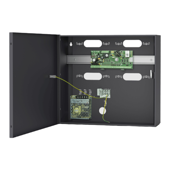
MC16-PAC-EX/ST-1-KIT is designed to control single door in RACS 5 system.
The door can be read-in or read-in/out type when equipped with MCT series
readers, OSDP-RS485 interface readers including OSR series readers, PRT
series readers or Wiegand interface readers. The kit includes MC16-PAC-EX/ST-
1 access controller and ME40-24V metal box with 24VDC/50W power supply
unit. The box is adapted to installation of 7Ah battery for emergency supply. All
elements of controlled door including readers and door lock can be supplied from
the kit.
C
R
ONFIGURATION WITH
OGER
Low level configuration with RogerVDM software enables to define basic
parameters of MC16 controller i.e. IP address and communication key.
MC16 programming procedure (RogerVDM):
1. Connect the controller to Ethernet network and define the IP address of your
computer in the same subnetwork as the controller with 192.168.0.213
default IP address.
2. Start RogerVDM program, select MC16 v1.x device, the latest firmware
version and Ethernet communication channel.
3. Select from the list or enter manually the IP address of controller, enter 1234
communication key and start the connection with the controller.
4. In the top menu select Tools and then Set communication key to define your
own password for the controller.
5. In the main window specify your own IP address of the controller.
6. Enable PRT or Wiegand readers if the controller is supposed to operate with
them.
7. Optionally enter comments for controller and its object to facilitate their
identification during further configuration of the system.
8. Optionally backup settings clicking Send to File...
9. Click Send to Device to update the configuration of controller and disconnect
by selection of Device in the top menu and then Disconnect.
Note: Initial low-level configuration of MC16 controller in RACS 5 v2 system
should be made with RogerVDM program, but further modification of low level
configuration for MC16 controller and connected MCT/MCX peripheral devices
can be made remotely with VISO v2 program.
C
VISO
ONFIGURATION WITH
High level configuration with VISO software enables to define the logic of
controller. More information is given in MC16 Operating manual and AN006
application note.
M
EMORY RESET
Memory reset procedure resets all settings to default ones and results in
192.168.0.213 IP address and empty communication key.
MC16 memory reset procedure:
1. Disconnect power supply.
2. Short CLK and IN4 lines.
3. Restore power supply, all LEDs will flash and wait min. 6s.
4. Remove connection between CLK and IN4 lines, LEDs will stop pulsating and
LED2 will be on.
5. Wait approx. 1.5 min till LED5+LED6+LED7+LED8 are pulsating.
6. Restart the controller (switch power supply off and on)
7. Start RogerVDM and make low level configuration.
F
IRMWARE UPDATE
New firmware can be uploaded to the controller with RogerVDM software or
VISO v2 software. The latest firmware file is available at www.roger.pl.
MC16 firmware update procedure (RogerVDM):
1. Connect with the controller using RogerVDM software.
2. Backup settings by clicking Send to File...
3. In the top menu select Tools and then Update firmware.
4. Select firmware file and then click Update.
5. After firmware update wait till LED8 is pulsating.
6. Make or restore low level configuration in RogerVDM software.
Roger Access Control System
MC16-PAC-EX/ST-1-KIT Installation Manual
Controller firmware version: 1.7.4.653 and newer
VDM
PROGRAM
PROGRAM
Product version: 3.0
Document version: Rev. B
Note: During the firmware update process, it is necessary to ensure continuous
and stable power supply for the device. If interrupted, the device may require
repair by Roger.
P
OWER SUPPLY
The kit is supplied from 24VDC/50W power supply unit. The metal box offers
space for installation of typical 7Ah backup battery which can be connected to
BAT+ and BAT- terminals of MC16 controller.
Fig. 1 MC16-PAC-EX/ST-1-KIT
T
AMPER DETECTOR
The metal box is equipped with door contact which can be connected to one of
the inputs (e.g. IN8) and GND terminal of the controller. The anti-sabotage
function can be assigned to the input with VISO program.
A
PPENDIX
Table 1. MC16 screw terminals
Name
BAT+, BAT-
AC, AC
AUX-, AUX+
TML-, TML+
IN1-IN8
GND
OUT1-OUT6
A1,B1
CLK, DTA
A2,B2
NO1, COM1, NC1
NO2, COM2, NC2
Table 2. MC16 LED indicators
Name
LED1
LED2
The installation can be done only by qualified person with all
necessary certificates concerning connection and maintenance
of 230VAC and low voltage networks.
Prior to starting the installation, it is necessary to ensure that
230 VAC circuit is disconnected. All works inside the box must
be carried out with 230VAC supply voltage disconnected.
It is forbidden to use the kit without properly executed and
operational earthing system.
Description
Backup battery
18VAC input power supply
12VDC/1.0 output power supply (for door lock)
12VDC/0.2A output power supply (for readers)
Input lines
Ground
15VDC/150mA transistor output lines
RS485 bus
RACS CLK/DTA bus
Not used
30V/1.5A DC/AC (REL1) relay
30V/1.5A DC/AC (REL2) relay
Description
Normal mode
ON: Service mode (low level configuration)
ON and controller stopped: RAM-SPI data initialization error
2023-12-07
1/2
Advertisement

Subscribe to Our Youtube Channel
Related Manuals for Roger MC16-PAC-EX/ST-1-KIT


Summary of Contents for Roger MC16-PAC-EX/ST-1-KIT
- Page 1 NTRODUCTION The kit is supplied from 24VDC/50W power supply unit. The metal box offers MC16-PAC-EX/ST-1-KIT is designed to control single door in RACS 5 system. space for installation of typical 7Ah backup battery which can be connected to The door can be read-in or read-in/out type when equipped with MCT series BAT+ and BAT- terminals of MC16 controller.
- Page 2 Weight of the equipment is specified in the document. Contact: Roger Sp. z o. o. sp. k. 82-400 Sztum Gościszewo 59 Tel.: +48 55 272 0132 Fax: +48 55 272 0133 Tech.
Need help?
Do you have a question about the MC16-PAC-EX/ST-1-KIT and is the answer not in the manual?
Questions and answers