Table of Contents
Advertisement
Quick Links
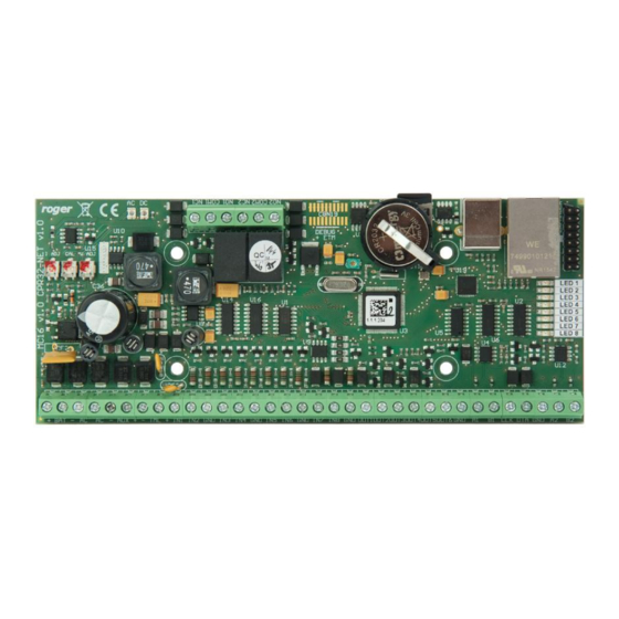
MC16 Installation Manual
This document contains minimum information that is necessary for initial setup
and installation of the device. The detailed description of configuration
parameters and functionalities is specified in respective Operating manual
available at www.roger.pl.
I
NTRODUCTION
MC16 controller is mainly dedicated to door access control in RACS 5 system.
The controller is master device for such peripheral devices as MCT and PRT
series terminals, Wiegand interface readers and MCX series expanders. Inputs
and outputs of the controller or connected peripheral device can be used to
control such devices as door locks, exit buttons, alarm sirens, etc. Various
versions and types of controllers are based on the same hardware module and
differ with license on their memory cards. Most popular MC16-PAC controllers
are offered in MC16-PAC-x-KIT sets.
C
R
ONFIGURATION WITH
OGER
Low level configuration with RogerVDM software enables to define basic
parameters of MC16 controller. Additionally it is necessary to define individual
addresses for MCT and PRT series readers and MCX expanders according to
their installation manuals.
MC16 programming procedure with RogerVDM software:
1. Connect the controller to Ethernet network and define the IP address of your
computer in the same subnetwork as the controller with 192.168.0.213
default IP address.
2. Start RogerVDM program, select MC16 v1.x device, the latest firmware
version and Ethernet communication channel.
3. Select from the list or enter manually the IP address of controller, enter 1234
communication key and start the connection with the controller.
4. In the top menu select Tools and then Set communication key to define your
own password for the controller.
5. In the main window specify your own IP address of the controller.
6. Enable PRT or Wiegand readers if the controller is supposed to operate with
them.
7. Optionally enter comments for controller and its object to facilitate their
identification during further configuration of the system.
8. Optionally backup settings clicking Send to File...
9. Click Send to Device to update the configuration of controller and disconnect
by selection of Device in the top menu and then Disconnect.
C
VISO
ONFIGURATION WITH
High level configuration with VISO software enables to define the logic of
controller. More information on scenarios of operation and high level
configuration is given in MC16 Operating manual as well as AN002 and AN006
application notes.
M
EMORY RESET
Memory reset procedure resets all settings to default ones and results in
192.168.0.213 IP address and empty communication key.
MC16 memory reset procedure:
1. Disconnect power supply.
2. Short CLK and IN4 lines.
3. Restore power supply, all LEDs will flash and wait min. 6s.
4. Remove connection between CLK and IN4 lines, LEDs will stop pulsating and
LED2 will be on.
5. Wait approx. 1.5 min till LED5+LED6+LED7+LED8 are pulsating.
6. Restart the controller (switch power supply off and on).
7. Start RogerVDM and make low level configuration.
F
IRMWARE UPDATE
New firmware can be uploaded to the controller with RogerVDM software. The
latest firmware file is available at www.roger.pl.
MC16 firmware update procedure:
1. Connect with the controller using RogerVDM software.
2. Backup settings by clicking Send to File...
3. In the top menu select Tools and then Update firmware.
4. Select firmware file and then click Update.
5. After firmware update wait till LED8 is pulsating.
6. Make or restore low level configuration in RogerVDM software.
Note: During the firmware update process, it is necessary to ensure continuous
and stable power supply for the device. If interrupted, the device may require
repair by Roger.
Roger Access Control System
MC16 Installation Manual
Firmware version: 1.6.4 and newer
Document version: Rev. I
VDM
PROGRAM
PROGRAM
P
OWER SUPPLY
MC16 controller is designed for power supply from 230VAC/18VAC transformer
with minimal power output 20VA, but it can also be supplied with 12VDC and
24VDC. In case of 12VDC power supply, backup battery cannot be directly
connected to MC16 and in such case backup power supply must be provided by
12VDC power supply unit.
Fig. 1 MC16 power supply
A
PPENDIX
Table 1. MC16 screw terminals
Name
Description
BAT+, BAT-
Backup battery
AC, AC
18VAC or 24VDC input power supply
AUX-, AUX+
12VDC/1.0 output power supply (for door lock)
TML-, TML+
12VDC/0.2A output power supply (for readers)
IN1-IN8
Input lines
GND
Ground
OUT1-OUT6
15VDC/150mA transistor output lines
A1,B1
RS485 bus
CLK, DTA
RACS CLK/DTA bus
A2,B2
Not used
NO1, COM1, NC1
30V/1.5A DC/AC (REL1) relay
NO2, COM2, NC2
30V/1.5A DC/AC (REL2) relay
Table 2. MC16 LED indicators
Name
Description
LED1
Normal mode
LED2
ON: Service mode (low level configuration)
Pulsing: RAM or Flash SPI memory error
LED3
ON: High level configuration error
Pulsing: Low level configuration error
LED4
No memory card or memory card error
LED5
Event log error
LED6
License error
LED7
Not used
LED8
Pulsating: Proper functioning of the controller
Table 3. Specification
Supply voltage
17-22VAC, nominal 18VAC
11.5V-15VDC, nominal 12VDC
22-26VDC, nominal 24VDC
Current consumption
100 mA for 18VAC (no loads on AUX/TML outputs)
2020-10-23
1/2
Advertisement
Table of Contents

Related Manuals for Roger MC16


Summary of Contents for Roger MC16
- Page 1 20VA, but it can also be supplied with 12VDC and available at www.roger.pl. 24VDC. In case of 12VDC power supply, backup battery cannot be directly connected to MC16 and in such case backup power supply must be provided by NTRODUCTION 12VDC power supply unit.
- Page 2 Diagrams include exit buttons. In case of read-in/out doors they can be used for emergency door opening. Fig. 2 Connection of readers and expanders to MC16 access controller Fig. 3 Typical door control with MCT readers This symbol placed on a product or packaging indicates that the product should not be disposed of with other wastes as this may have a negative impact on the environment and health.
Need help?
Do you have a question about the MC16 and is the answer not in the manual?
Questions and answers