Table of Contents
Advertisement
Quick Links
MC16-SVC Installation Manual
This document contains minimum information that is necessary for initial setup
and installation of the device. The detailed description of configuration
parameters and functionalities is specified in respective Operating manual
available at www.roger.pl.
I
NTRODUCTION
MC16-SVC controller is dedicated to demo or service operation in RACS 5
system. The controller is delivered with a set of licenses that enable its switching
to an operating mode compatible with various functional versions of the MC16
series controller. MC16-SVC controller can be operated as:
access controller for 16 doors (MC16-PAC-16)
access controller for 64 lockers (MC16-LRC-64)
universal elevator access controller for 64 floors (MC16-EVC-64)
Factory new device is configured for operation as MC16-PAC-16 controller.
LICENSES PARAMETERS
Table 1. MC16-SVC licenses
Type
MC16-PAC-16
Access Doors
16
Access Points
32
Inputs
96
Outputs
56
Function Keys
128
Local Commands
32
Access Zones
32
Alarm Zones
32
Automation Nodes
32
Power Supplies
32
Access
Doors
per
1
Access Points
LICENSE REPLACEMENT
License replacement procedure:
1. Switch off the power supply of MC16
controller.
2. Press memory card and remove it
from the socket under CR2032
battery on controller board.
3. Insert card into standard
Flash
memory card reader and connect it
to computer's USB port.
4. Copy required license file from
LICENSES folder into main folder of
the card and change the name of the
file into LICENSE.CFG.
5. Open and configure DEBUG.CFG
file on memory card as needed (see
below) to select demo or service
mode.
6. Insert the card into controller socket.
7. Switch on the power supply of MC16
controller.
D
EMO AND SERVICE MODE
If the parameter EVL=1 is entered in DEBUG.CFG file on memory card then the
controller operation on each day is limited to 6:00 am – 10:00 pm period. This is
called demo mode and is offered for the purpose of MC16 evaluation and
demonstration.
If the parameter EVL=0 or is not defined at all then the parameter STD in the
format YY/MM/DD (e.g. STD=20/03/30) defines starting date for controller
operation. This is called service mode and it is offered for the purpose of MC16
servicing e.g. temporary device replacement due to failure. In this mode the
controller can be operated for 10 days. When the time expires, then the controller
automatically suspends normal operation. In order to restart the work, it is
necessary to set a new start date in the DEBUG.CFG file. The controller working
time can be extended any number of times and the extension for another period
may take place during the previous period.
C
R
ONFIGURATION WITH
OGER
Low level configuration with RogerVDM software enables to define basic
parameters of MC16 controller. Additionally it is necessary to define individual
Roger Access Control System
MC16-SVC Installation Manual
Firmware version: 1.6.4 or newer
Document version: Rev. B
MC16-LRC-64
MC16-EVC-64
64
64
16 (MCT) or
1
64 (RWL-3)
128
8
128
128
32
8
16
4
0
0
0
0
2
2
16
16
64
64
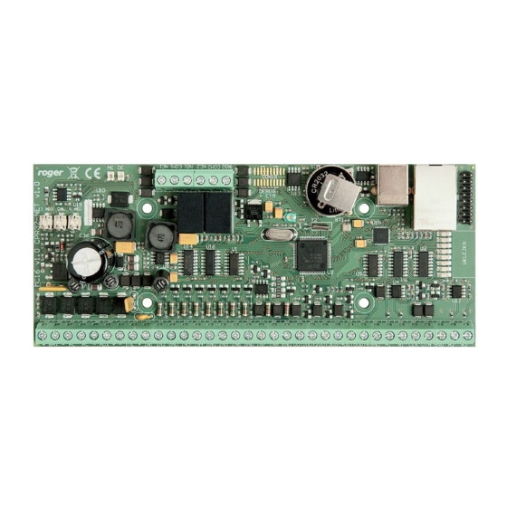
Fig. 1 MC16 memory card
VDM
PROGRAM
addresses for MCT and PRT series readers and MCX expanders according to
their installation manuals.
MC16 programming procedure with RogerVDM software:
1. Connect the controller to Ethernet network and define the IP address of your
computer in the same subnetwork as the controller with 192.168.0.213
default IP address.
2. Start RogerVDM program, select MC16 v1.x device, the latest firmware
version and Ethernet communication channel.
3. Select from the list or enter manually the IP address of controller, enter 1234
communication key and start the connection with the controller.
4. In the top menu select Tools and then Set communication key to define your
own password for the controller.
5. In the main window specify your own IP address of the controller.
6. Enable PRT or Wiegand readers if the controller is supposed to operate with
them
7. Optionally enter comments for controller and its object to facilitate their
identification during further configuration of the system.
8. Optionally backup settings clicking Send to File...
9. Click Send to Device to update the configuration of controller and disconnect
by selection of Device in the top menu and then Disconnect.
C
VISO
ONFIGURATION WITH
High level configuration with VISO software enables to define the logic of
controller. More information on scenarios of operation and high level
configuration is given in MC16 Operating manual as well as AN002, AN006 and
other application notes.
M
EMORY RESET
Memory reset procedure resets all settings to default ones and results in
192.168.0.213 IP address and empty communication key.
MC16 memory reset procedure:
1. Disconnect power supply.
2. Short CLK and IN4 lines.
3. Restore power supply, all LEDs will flash and wait min. 6s.
4. Remove connection between CLK and IN4 lines, LEDs will stop pulsating and
LED2 will be on.
5. Wait approx. 1.5 min till LED5+LED6+LED7+LED8 are pulsating.
6. Restart the controller (switch power supply off and on).
7. Start RogerVDM and make low level configuration.
F
IRMWARE UPDATE
New firmware can be uploaded to the controller with RogerVDM software. The
latest firmware file is available at www.roger.pl.
MC16 firmware update procedure:
1. Connect with the controller using RogerVDM software.
2. Backup settings by clicking Send to File...
3. In the top menu select Tools and then Update firmware.
4. Select firmware file and then click Update.
5. After firmware update wait till LED8 is pulsating.
6. Make or restore low level configuration in RogerVDM software.
Note: During the firmware update process, it is necessary to ensure continuous
and stable power supply for the device. If interrupted, the device may require
repair by Roger.
P
OWER SUPPLY
MC16 controller is designed for power supply from 230VAC/18VAC transformer
with minimal power output 20VA, but it can also be supplied with 12VDC or
24VDC. In case of 12VDC power supply, backup battery cannot be directly
connected to MC16 and in such case backup power supply must be provided by
12VDC power supply unit.
2020-04-03
PROGRAM
1/2
Advertisement
Table of Contents

Related Manuals for Roger MC16-PAC-16


Summary of Contents for Roger MC16-PAC-16
- Page 1 5. In the main window specify your own IP address of the controller. 6. Enable PRT or Wiegand readers if the controller is supposed to operate with Factory new device is configured for operation as MC16-PAC-16 controller. them 7. Optionally enter comments for controller and its object to facilitate their LICENSES PARAMETERS identification during further configuration of the system.
- Page 2 Weight of the equipment is specified in the document. Contact: Roger Sp. z o. o. sp. k. 82-400 Sztum Gościszewo 59 Tel.: +48 55 272 0132 Fax: +48 55 272 0133 Tech.
Need help?
Do you have a question about the MC16-PAC-16 and is the answer not in the manual?
Questions and answers