Table of Contents
Advertisement
Quick Links
DRV2604 ERM, LRA Haptic Driver Evaluation Kit
The DRV2604 is a haptic driver designed for Linear Resonant Actuators (LRA) and Eccentric Rotating
Mass (ERM) motors. It provides many features which help eliminate the design complexities of haptic
motor control including reduced solution size, high efficiency output drive, closed-loop motor control, quick
device startup, memory for waveform storage, and auto-resonance frequency tracking.
The DRV2604EVM-CT Evaluation Module (EVM) is a complete demo and evaluation platform for the
DRV2604. The kit includes a microcontroller, linear actuator, eccentric rotating mass motor, and capacitive
touch buttons which can be used to completely demonstrate and evaluate the DRV2604.
This document contains instructions to setup and operate the DRV2604EVM-CT in demo and evaluation
mode.
Evaluation Kit Contents:
•
DRV2604EVM-CT demo and evaluation board
•
Mini-USB cable
•
Demonstration Firmware
Required for programming and advanced configuration:
•
Code Composer Studio™ (CCS) or IAR Embedded Workbench IDE for MSP430
•
MSP430 LaunchPad (MSP-EXP430G2), or MSP430-FET430UIF hardware programming tool
•
DRV2604EVM-CT firmware available on
Code Composer Studio is a trademark of Texas Instruments.
2
I
C is a trademark of NXP.
SLOU355 – March 2013
Submit Documentation Feedback
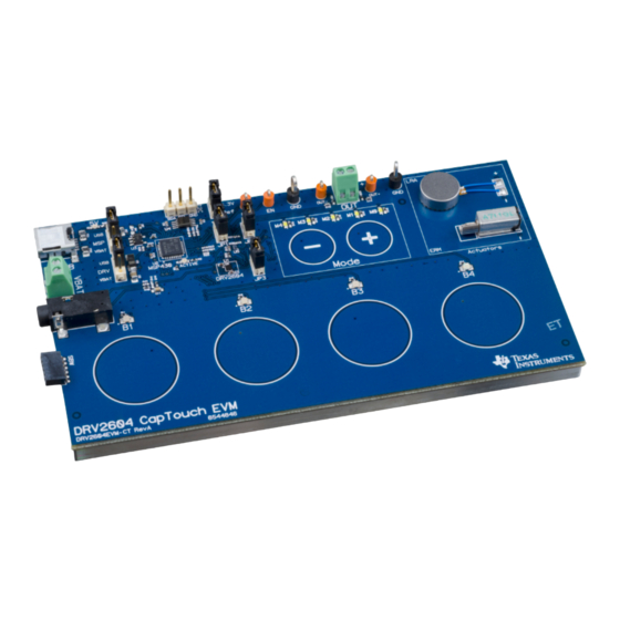
Figure 1. DRV2604EVM-CT Board
ti.com
Copyright © 2013, Texas Instruments Incorporated
SLOU355 – March 2013
DRV2604 ERM, LRA Haptic Driver Evaluation Kit
User's Guide
1
Advertisement
Table of Contents

Related Manuals for Texas Instruments DRV2604EVM-CT


Summary of Contents for Texas Instruments DRV2604EVM-CT
-
Page 1: Drv2604Evm-Ct Board
The DRV2604EVM-CT Evaluation Module (EVM) is a complete demo and evaluation platform for the DRV2604. The kit includes a microcontroller, linear actuator, eccentric rotating mass motor, and capacitive touch buttons which can be used to completely demonstrate and evaluate the DRV2604. -
Page 2: Table Of Contents
DRV2604 Unfiltered Waveform .................... DRV2604 Filtered Waveform .......... Measuring the DRV2604 Output Signal with an Analog Low-Pass Filter ................... LaunchPad Programmer Connection DRV2604 ERM, LRA Haptic Driver Evaluation Kit SLOU355 – March 2013 Submit Documentation Feedback Copyright © 2013, Texas Instruments Incorporated... - Page 3 Bottom Copper List of Tables ....................Mode and Effects Table ....................Binary Counting Modes ....................... Hardware Overview ......................MSP430 Pin-Out SLOU355 – March 2013 DRV2604 ERM, LRA Haptic Driver Evaluation Kit Submit Documentation Feedback Copyright © 2013, Texas Instruments Incorporated...
-
Page 4: Getting Started
Getting Started The DRV2604 can be used as a demonstration or evaluation tool. When the DRV2604EVM-CT evaluation module is powered on for the first time, a demo application automatically starts. To power the board, connect the DRV2604EVM-CT to an available USB port on your computer using the included mini-USB cable. -
Page 5: Evaluation Module Operating Parameters
Select USB (5 V) or VBAT power for the DRV2604 2. Connect the included mini-USB cable to the USB connector on the DRV2604EVM-CT board. 3. Connect the other end of the USB cable to an available USB port on a computer, USB charger, or USB battery pack. -
Page 6: Drv2604 Demonstration Program
DRV2604 Demonstration Program The sections below provide a detailed description of the demo modes and effects. Modes and Effects Table The effects preloaded on the DRV2604EVM-CT are listed in Table 1. The modes are selected using the + and – mode buttons in the center of the board. The current mode is identified by the white LEDs directly above the mode buttons. -
Page 7: Description Of The Demo Modes
Figure 5. ERM Closed-Loop Click Waveform (Button 1) Figure 6. ERM Open-Loop Click Waveform (Button 4) SLOU355 – March 2013 DRV2604 ERM, LRA Haptic Driver Evaluation Kit Submit Documentation Feedback Copyright © 2013, Texas Instruments Incorporated... -
Page 8: Lra Closed-Loop Click Waveform (Button 1)
With the Smart Loop auto-resonance feature, the DRV2604 dynamically tracks the exact resonant frequency to maximize the vibration force. DRV2604 ERM, LRA Haptic Driver Evaluation Kit SLOU355 – March 2013 Submit Documentation Feedback Copyright © 2013, Texas Instruments Incorporated... -
Page 9: Acceleration Versus Frequency
5. After each successfully repeated pattern, the board repeats the same pattern and adds one additional button effect to the sequence. SLOU355 – March 2013 DRV2604 ERM, LRA Haptic Driver Evaluation Kit Submit Documentation Feedback Copyright © 2013, Texas Instruments Incorporated... -
Page 10: Ram Library Mode
Light Double Click Strong Triple Click Buzz Ramp Up Ramp Down Click + Bounce Ramp Up + Click Gallop Alert Pulsing Alert DRV2604 ERM, LRA Haptic Driver Evaluation Kit SLOU355 – March 2013 Submit Documentation Feedback Copyright © 2013, Texas Instruments Incorporated... -
Page 11: Additional Hardware Modes
Additional Hardware Modes Additional modes are available on the DRV2604EVM-CT providing increased board control and functionality. The additional modes are not available in demo mode, but can be accessed by switching to binary counting mode. In binary counting mode the mode LEDs count in binary (32 modes) rather than in demo mode format (only 6 modes including off). -
Page 12: Binary Counting Modes
About the Board - the value will appear on the mode LEDs in binary. About the Board DRV2604 Device ID = 00100 Silicon Revision LEDs: 11111 Code Revision DRV2604 ERM, LRA Haptic Driver Evaluation Kit SLOU355 – March 2013 Submit Documentation Feedback Copyright © 2013, Texas Instruments Incorporated... -
Page 13: Hardware Configuration
Hardware configuration details can be found in the following sections. Power Supply Selection The DRV2604EVM-CT can be powered by USB or an external power supply (VBAT). Jumpers DRV and MSP are used to select USB or VBAT for the DRV2604 and MSP430G2553, respectively. See the following table for possible configurations. -
Page 14: Using An External Actuator
From DRV2604 Figure 14. Terminal Block and Test Points The DRV2604EVM-CT can be used with an external actuator. Follow the instructions below to attach an actuator to the OUT terminal block. 1. Remove jumpers JP3 and JP4, which disconnects the on-board actuators from the DRV2604. -
Page 15: External Trigger Control
LEDs. 6. Apply the trigger signal to the IN/TRIG pin by pressing the B4 button. SLOU355 – March 2013 DRV2604 ERM, LRA Haptic Driver Evaluation Kit Submit Documentation Feedback Copyright © 2013, Texas Instruments Incorporated... -
Page 16: External I C Input
3. Choose either the on-board ERM or LRA using buttons B1 or B2. Either button sets the EN pin high and turns on the Active LED. 4. Begin controlling the DRV2604 using the external I C source. DRV2604 ERM, LRA Haptic Driver Evaluation Kit SLOU355 – March 2013 Submit Documentation Feedback Copyright © 2013, Texas Instruments Incorporated... -
Page 17: Analog Input
OUT+ and OUT–. OUT- OUT+ 470pF 470pF 100k 100k From DRV2604 Figure 19. Terminal Block and Test Points SLOU355 – March 2013 DRV2604 ERM, LRA Haptic Driver Evaluation Kit Submit Documentation Feedback Copyright © 2013, Texas Instruments Incorporated... -
Page 18: Drv2604 Unfiltered Waveform
Figure 20. DRV2604 Unfiltered Waveform Figure 21. DRV2604 Filtered Waveform If the DRV2604EVM-CT filter is not used, TI recommends using a 1st-order, low-pass filter with a cutoff between 1kHz and 3.5kHz . Below is a recommended output filter for use while measuring and characterizing the DRV2604 in the lab. -
Page 19: Modifying Or Reprogramming The Firmware
Modifying or Reprogramming the Firmware The MSP430 firmware on the DRV2604EVM-CT can be modified or reprogrammed to create new haptic effects or behaviors. Find the latest firmware source code and binaries on ti.com. Follow the instructions below to modify or reprogram the DRV2604EVM-CT. -
Page 20: Msp430 Pin-Out
Modifying or Reprogramming the Firmware www.ti.com MSP430 Pin-Out The DRV2604EVM-CT contains a MSP430G2553 low-cost microcontroller which controls the board and contains sample haptic effects. The pin-out for the microcontroller is found in Table Table 4. MSP430 Pin-Out Label Description P1.1 Green LED P1.2... -
Page 21: Schematic
470pfd/50V Black 6A/125V 0.1ufd/10V 0402 X7R 0402 0603 X7R 0.1ufd/6.3V 0402 0402 SJ-3523-SMT 3.5mm Audio-to-Haptics QFN32-RHB Figure 24. DRV2604EVM-CT Schematic SLOU355 – March 2013 DRV2604 ERM, LRA Haptic Driver Evaluation Kit Submit Documentation Feedback Copyright © 2013, Texas Instruments Incorporated... -
Page 22: Layout
Layout www.ti.com Layout Figure 25. X-Ray Top View spacer Figure 26. Top Copper DRV2604 ERM, LRA Haptic Driver Evaluation Kit SLOU355 – March 2013 Submit Documentation Feedback Copyright © 2013, Texas Instruments Incorporated... -
Page 23: Layer 2 Copper
Layout www.ti.com Figure 27. Layer 2 Copper spacer Figure 28. Layer 3 Copper SLOU355 – March 2013 DRV2604 ERM, LRA Haptic Driver Evaluation Kit Submit Documentation Feedback Copyright © 2013, Texas Instruments Incorporated... -
Page 24: Bottom Copper
Layout www.ti.com Figure 29. Bottom Copper DRV2604 ERM, LRA Haptic Driver Evaluation Kit SLOU355 – March 2013 Submit Documentation Feedback Copyright © 2013, Texas Instruments Incorporated... -
Page 25: Bill Of Materials
MANU PARTNUM REF DESIGNATORS VENDOR PARTNUM DESCRIPTION MANUFACTURER SEMICONDUCTORS DRV2604YZF DRV2604YZF HAPTIC DRIVER AUTO DETECT FOR TEXAS INSTRUMENTS LRA AND ERM WCSP9-YZF ROHS TXS0102DCTR 296-21978-1 2-BIT BIDIR LEVEL TRANSLATOR TEXAS INSTRUMENTS SSOP8-DCT ROHS MSP430G2553IRHB32T 595-P430G2553IRHB32T MIXED SIGNAL MICRO 16KB FLASH... - Page 26 ROHS 5003 PWM,ENIN, OUT+, 5003K PC TESTPOINT, ORANGE, ROHS KEYSTONE ELECTRONICS OUT– (Solder so that color ring is secured) DRV2604 ERM, LRA Haptic Driver Evaluation Kit SLOU355 – March 2013 Submit Documentation Feedback Copyright © 2013, Texas Instruments Incorporated...
- Page 27 TESTPOINT SMD SQUARE 2.0mm Square_2.0mm R0402_DNP R20,R21,R22,R23,R24,R R0402_DNP 25,R30,R31,R35 R0603_DNP RMCF0603ZT0R00CT- R0603_DNP STACKPOLE ELECTRONICS R0402_DNP P4.99KLCT-ND R0402_DNP PANASONIC R0402_DNP 541-0.0JCT R0402_DNP VISHAY SLOU355 – March 2013 DRV2604 ERM, LRA Haptic Driver Evaluation Kit Submit Documentation Feedback Copyright © 2013, Texas Instruments Incorporated...
- Page 28 Any exceptions to this are strictly prohibited and unauthorized by Texas Instruments unless user has obtained appropriate experimental/development licenses from local regulatory authorities, which is responsibility of user including its acceptable authorization.
- Page 29 FCC Interference Statement for Class B EVM devices This equipment has been tested and found to comply with the limits for a Class B digital device, pursuant to part 15 of the FCC Rules. These limits are designed to provide reasonable protection against harmful interference in a residential installation. This equipment generates, uses and can radiate radio frequency energy and, if not installed and used in accordance with the instructions, may cause harmful interference to radio communications.
- Page 30 Also, please do not transfer this product, unless you give the same notice above to the transferee. Please note that if you could not follow the instructions above, you will be subject to penalties of Radio Law of Japan. Texas Instruments Japan Limited (address) 24-1, Nishi-Shinjuku 6 chome, Shinjuku-ku, Tokyo, Japan http://www.tij.co.jp...
- Page 31 FDA Class III or similar classification, then you must specifically notify TI of such intent and enter into a separate Assurance and Indemnity Agreement. Mailing Address: Texas Instruments, Post Office Box 655303, Dallas, Texas 75265 Copyright © 2013, Texas Instruments Incorporated...
- Page 32 IMPORTANT NOTICE Texas Instruments Incorporated and its subsidiaries (TI) reserve the right to make corrections, enhancements, improvements and other changes to its semiconductor products and services per JESD46, latest issue, and to discontinue any product or service per JESD48, latest issue.
- Page 33 Mouser Electronics Authorized Distributor Click to View Pricing, Inventory, Delivery & Lifecycle Information: Texas Instruments DRV2604EVM-CT...
Need help?
Do you have a question about the DRV2604EVM-CT and is the answer not in the manual?
Questions and answers