Table of Contents
Advertisement
Quick Links
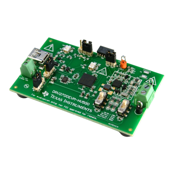
DRV2700EVM-HV500 High Voltage Piezo Driver Evaluation
The DRV2700 is a single chip high-voltage driver with an integrated 105-V boost switch, integrated power
diode, and integrated fully differential amplifier. This evaluation kit utilizes this high-voltage switch into a
flyback configuration that is able to achieve (but is not limited to) up to 500 V:
•
Controllable input modes: Analog input, PWM and MSP430 controllable
•
Variable output voltages from 0 V to 500 V
•
2 power supply inputs to isolate power consumption on DRV2700 application circuitry
•
4 convenient max output voltage settings
•
Small footprint (14 mm x 14.5 mm)
The evaluation kit is designed for all-around use and can be used not only for evaluation but can also be
used for prototyping into systems for driving piezo actuators, polymers, valves and many other
applications. The EVM also contains a microcontroller, LDO (3.3 V) and LEDs for status and input
settings.
Evaluation Kit Contents:
•
DRV2700EVM-HV500 evaluation board
•
Demonstration mode firmware preloaded onto microcontroller
•
Downloadable software to control EVM
•
Mini-B USB cable
Needed for programming and advanced configuration:
•
Code Composer Studio™ (CCS) for MSP430
•
MSP430 LaunchPad™ (MSP-EXP430G2) or MSP430-FET430UIF hardware programming tool
•
DRV2700EVM firmware available on the
Code Composer Studio, LaunchPad are trademarks of Texas Instruments.
SLOU407A – April 2015 – Revised May 2015
Submit Documentation Feedback
DRV2700EVM-HV500 tool folder
DRV2700EVM-HV500 High Voltage Piezo Driver Evaluation Kit
Copyright © 2015, Texas Instruments Incorporated
User's Guide
SLOU407A – April 2015 – Revised May 2015
Kit
1
Advertisement
Table of Contents

Subscribe to Our Youtube Channel
Related Manuals for Texas Instruments DRV2700EVM-HV500


Summary of Contents for Texas Instruments DRV2700EVM-HV500
- Page 1 MSP430 LaunchPad™ (MSP-EXP430G2) or MSP430-FET430UIF hardware programming tool • DRV2700EVM firmware available on the DRV2700EVM-HV500 tool folder Code Composer Studio, LaunchPad are trademarks of Texas Instruments. SLOU407A – April 2015 – Revised May 2015 DRV2700EVM-HV500 High Voltage Piezo Driver Evaluation Kit Submit Documentation Feedback...
-
Page 2: Table Of Contents
Pulldown Network ......................With FET Pulldown ..................... Without FET Pulldown ........................Input Filter ..................DRV2700EVM-HV500 Schematic DRV2700EVM-HV500 High Voltage Piezo Driver Evaluation Kit SLOU407A – April 2015 – Revised May 2015 Submit Documentation Feedback Copyright © 2015, Texas Instruments Incorporated... - Page 3 And may require export or re-export license for shipping it in compliance with the applicable regulations of certain countries. SLOU407A – April 2015 – Revised May 2015 DRV2700EVM-HV500 High Voltage Piezo Driver Evaluation Kit Submit Documentation Feedback Copyright © 2015, Texas Instruments Incorporated...
- Page 4 Danger High Voltage! Electric shock possible when connecting board to live wire. Board should be handled with care by a professional. For safety, use of isolated test equipment with overvoltage/overcurrent protection is highly recommended. DRV2700EVM-HV500 High Voltage Piezo Driver Evaluation Kit SLOU407A – April 2015 – Revised May 2015 Submit Documentation Feedback...
- Page 5 Any other use and/or application are strictly prohibited by Texas Instruments. If you are not suitable qualified, you should immediately stop from further use of the HV EVM.
-
Page 6: Getting Started
EVM. To power the board, connect the DRV2700EVM-HV500 to an available USB port on your computer using a mini-B USB cable. The default board settings cause the microcontroller (MSP430) to control the inputs of the DRV2700 at power up. The MSP430 has each of these control settings low which disables the DRV2700, by default. -
Page 7: Quick Start Board Setup
Quick Start Board Setup The DRV2700EVM-HV500 comes with preprogrammed firmware to provide a 0- to 500-Vp signal between the output and GND. 1. Out of the box, the jumpers are set to begin demo mode using USB power. The default jumper settings... -
Page 8: Overview Of Evm
USB power and the DRV jumper (JP4) with VIN. With this configuration, measuring the provided voltage and current into VIN gives the power consumption of the DRV2700. DRV2700EVM-HV500 High Voltage Piezo Driver Evaluation Kit SLOU407A – April 2015 – Revised May 2015 Submit Documentation Feedback Copyright ©... -
Page 9: Configuration
Outputs The DRV2700EVM-HV500 has a high voltage output ranging from 0–500 V. This output is routed to a terminal connector to mitigate the user touching between the high voltage node and GND. Be sure to disable power when connecting and disconnecting the high voltage node. -
Page 10: Evm Control Software (Gui)
EVM Control Software (GUI) www.ti.com EVM Control Software (GUI) By default, the DRV2700EVM-HV500 can be controlled programmatically through the GUI Interface. Figure 4 is a screenshot of the GUI. Run the GUI by downloading it from the DRV2700EVM-HV500 tool folder, installing the GUI and then running it. -
Page 11: Low Pwm Frequency
It is best practice to have an oscilloscope measure the output to verify how the load is actually being driven, based on the conditions applied. SLOU407A – April 2015 – Revised May 2015 DRV2700EVM-HV500 High Voltage Piezo Driver Evaluation Kit Submit Documentation Feedback Copyright © 2015, Texas Instruments Incorporated... -
Page 12: Flyback Converter
Before connecting the load, ensure the load is rated for the current boost voltage setting. Programming the HV Maximum Output Voltage for more information on how to set the boost voltage. DRV2700EVM-HV500 High Voltage Piezo Driver Evaluation Kit SLOU407A – April 2015 – Revised May 2015 Submit Documentation Feedback... -
Page 13: Programming The Hv Maximum Output Voltage
0.866 MΩ 22 pF 212 V Down 5.49 kΩ 2710 pF 0.642 MΩ 22 pF 158 V SLOU407A – April 2015 – Revised May 2015 DRV2700EVM-HV500 High Voltage Piezo Driver Evaluation Kit Submit Documentation Feedback Copyright © 2015, Texas Instruments Incorporated... -
Page 14: Programming The Flyback Current Limit
Additionally, a non-populated landing pad (C6) is provided for additional capacitance, if desired. DRV2700EVM-HV500 High Voltage Piezo Driver Evaluation Kit SLOU407A – April 2015 – Revised May 2015 Submit Documentation Feedback Copyright ©... -
Page 15: Pwm And Analog Inputs
When using the DRV2700EVM-HV500 in MSP430 PWM input mode, the onboard MSP430 generates a PWM signal that is sent through a low-pass filter to the DRV2700. The DRV2700EVM-HV500 is set up to use this mode by default. Set to the default settings to use this input mode. -
Page 16: Analog Input
(LOAD) Input Frequency = 10 Hz Figure 12. 100-Hz Input Signal Figure 11. 10-Hz Input Signal DRV2700EVM-HV500 High Voltage Piezo Driver Evaluation Kit SLOU407A – April 2015 – Revised May 2015 Submit Documentation Feedback Copyright © 2015, Texas Instruments Incorporated... -
Page 17: Output
SLOU407A – April 2015 – Revised May 2015 DRV2700EVM-HV500 High Voltage Piezo Driver Evaluation Kit Submit Documentation Feedback Copyright © 2015, Texas Instruments Incorporated... -
Page 18: Pulldown Network
= 0 to 500 V (LOAD) (LOAD) 500us/div 2ms/div Figure 15. With FET Pulldown Figure 16. Without FET Pulldown DRV2700EVM-HV500 High Voltage Piezo Driver Evaluation Kit SLOU407A – April 2015 – Revised May 2015 Submit Documentation Feedback Copyright © 2015, Texas Instruments Incorporated... -
Page 19: Input Filter
Input Filter The DRV2700EVM-HV500 has an active low-pass input filter to attenuate high frequency PWM signals coming from the input source. Depending on the input frequency and input voltage, the filter can be adapted to attenuate any undesired out-of-band content. This section describes the input filter requirements and the various respective configurations. -
Page 20: Reference
Reference www.ti.com Reference This section includes the DRV2700EVM-HV500 schematic, PCB layout, and bill of materials. Schematic Figure 18 illustrates the DRV2700EVM-HV500 schematic. 3900pF DRV2700 HV DANGER HIGH VOLTAGE INPUT VDRV VDRV VBUS 69.8k Filter_Out 0.1µF 5.1k VGate 90.9k VBUS 0.1uF 5.6V... -
Page 21: Pcb Layout
PCB Layout Figure 19 shows the DRV2700EVM-HV500 PCB layout. Figure 19. Top and Bottom Layers SLOU407A – April 2015 – Revised May 2015 DRV2700EVM-HV500 High Voltage Piezo Driver Evaluation Kit Submit Documentation Feedback Copyright © 2015, Texas Instruments Incorporated... -
Page 22: Bill Of Materials
Sullins Connector Solutions Unless otherwise noted in the Alternate Part Number and/or Alternate Manufacturer columns, all parts may be substituted with equivalents. DRV2700EVM-HV500 High Voltage Piezo Driver Evaluation Kit SLOU407A – April 2015 – Revised May 2015 Submit Documentation Feedback... - Page 23 HIGH-SPEED DATA INTERFACES, DRY006A Piezo Driver with Integrated Boost Converter, RGP0020D DRV2700RGP Texas Instruments Texas RGP0020D Instruments SLOU407A – April 2015 – Revised May 2015 DRV2700EVM-HV500 High Voltage Piezo Driver Evaluation Kit Submit Documentation Feedback Copyright © 2015, Texas Instruments Incorporated...
- Page 24 GRM32DR72J473KW01L Murata 1210 FID1, FID2, Fiducial mark. There is nothing to buy or mount. Fiducial FID3 DRV2700EVM-HV500 High Voltage Piezo Driver Evaluation Kit SLOU407A – April 2015 – Revised May 2015 Submit Documentation Feedback Copyright © 2015, Texas Instruments Incorporated...
- Page 25 ......................• Changed GUI Interface image. NOTE: Page numbers for previous revisions may differ from page numbers in the current version. SLOU407A – April 2015 – Revised May 2015 Revision History Submit Documentation Feedback Copyright © 2015, Texas Instruments Incorporated...
- Page 26 STANDARD TERMS AND CONDITIONS FOR EVALUATION MODULES Delivery: TI delivers TI evaluation boards, kits, or modules, including any accompanying demonstration software, components, or documentation (collectively, an “EVM” or “EVMs”) to the User (“User”) in accordance with the terms and conditions set forth herein. Acceptance of the EVM is expressly subject to the following terms and conditions.
- Page 27 FCC Interference Statement for Class B EVM devices NOTE: This equipment has been tested and found to comply with the limits for a Class B digital device, pursuant to part 15 of the FCC Rules. These limits are designed to provide reasonable protection against harmful interference in a residential installation.
- Page 28 【無線電波を送信する製品の開発キットをお使いになる際の注意事項】 開発キットの中には技術基準適合証明を受けて いないものがあります。 技術適合証明を受けていないもののご使用に際しては、電波法遵守のため、以下のいずれかの 措置を取っていただく必要がありますのでご注意ください。 1. 電波法施行規則第6条第1項第1号に基づく平成18年3月28日総務省告示第173号で定められた電波暗室等の試験設備でご使用 いただく。 2. 実験局の免許を取得後ご使用いただく。 3. 技術基準適合証明を取得後ご使用いただく。 なお、本製品は、上記の「ご使用にあたっての注意」を譲渡先、移転先に通知しない限り、譲渡、移転できないものとします。 上記を遵守頂けない場合は、電波法の罰則が適用される可能性があることをご留意ください。 日本テキサス・イ ンスツルメンツ株式会社 東京都新宿区西新宿6丁目24番1号 西新宿三井ビル 3.3.3 Notice for EVMs for Power Line Communication: Please see http://www.tij.co.jp/lsds/ti_ja/general/eStore/notice_02.page 電力線搬送波通信についての開発キットをお使いになる際の注意事項については、次のところをご覧くださ い。http://www.tij.co.jp/lsds/ti_ja/general/eStore/notice_02.page SPACER EVM Use Restrictions and Warnings: 4.1 EVMS ARE NOT FOR USE IN FUNCTIONAL SAFETY AND/OR SAFETY CRITICAL EVALUATIONS, INCLUDING BUT NOT LIMITED TO EVALUATIONS OF LIFE SUPPORT APPLICATIONS.
- Page 29 Notwithstanding the foregoing, any judgment may be enforced in any United States or foreign court, and TI may seek injunctive relief in any United States or foreign court. Mailing Address: Texas Instruments, Post Office Box 655303, Dallas, Texas 75265 Copyright © 2015, Texas Instruments Incorporated...
- Page 30 IMPORTANT NOTICE Texas Instruments Incorporated and its subsidiaries (TI) reserve the right to make corrections, enhancements, improvements and other changes to its semiconductor products and services per JESD46, latest issue, and to discontinue any product or service per JESD48, latest issue.
Need help?
Do you have a question about the DRV2700EVM-HV500 and is the answer not in the manual?
Questions and answers